
Related Manuals for Ruijie Reyee RG-ES106D-P V2


Summary of Contents for Ruijie Reyee RG-ES106D-P V2
- Page 1 Ruijie Reyee RG-ES106D-P V2 Switch Hardware Installation and Reference Guide Document Version: V1.1 Date: 2022-11-29 Copyright © 2022 Ruijie Networks...
- Page 2 Due to product version upgrades or other reasons, the content of this document will be updated from time to time. Ruijie Networks reserves the right to modify the content of the document without any notice or prompt. This manual is for reference only. Ruijie Networks endeavors to ensure content accuracy and will not shoulder...
-
Page 3: Preface
Technical support and servicing engineers Network administrators Technical Support The official website of Ruijie Reyee: https://www.ruijienetworks.com/products/reyee Conventions Signs The symbols used in this document are described as follows: Danger An alert that calls attention to safety operation instructions that if not understood or followed when operating the device can result in physical injury. -
Page 4: Table Of Contents
Contents Preface ..............................I 1 Product Overview ..........................1 1.1 Package Contents........................1 1.2 Appearance ..........................1 1.2.1 Front Panel ........................2 1.2.2 Rear Panel ........................3 1.3 Technical Specifications ......................3 1.4 Cooling ............................5 2 Preparing for Installation ........................6 2.1 Safety Precautions ........................ - Page 5 2.2.9 Installation Site Requirements ..................10 2.3 Tools ............................10 3 Installing the Switch ........................11 3.1 Before You Begin ........................11 3.2 Precautions ..........................11 3.3 Mounting the Switch ........................ 12 3.3.1 Mounting the Switch on a Wall ..................12 3.3.2 Mounting the Switch on a Workbench .................
-
Page 6: Product Overview
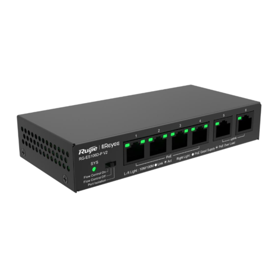
Hardware Installation and Reference Guide Product Overview Product Overview RG-ES106D-P V2 is a 100M Ethernet PoE switch, providing six 10/100 Mbps self-adaptive Ethernet RJ45 ports with line-rate forwarding performance. As four ports are PoE-capable and are backward compliant with IEEE802.3at standard, the RG-ES106D-P V2 can serve as a PoE device. The switch can automatically identify the powered devices compliant with IEEE802.3at/af standard and supply power for such devices through Ethernet cables. -
Page 7: Front Panel
Hardware Installation and Reference Guide Product Overview Figure 1-2 Appearance of a RG-ES106D-P V2 Switch 1.2.1 Front Panel Figure 1-3 Front Panel of a RG-ES106D-P V2 Switch Table 1-2 Front Panel Specifications Item Description Off: The device is not powered on. System Status LED Solid on: The device is powered on. -
Page 8: Rear Panel
Hardware Installation and Reference Guide Product Overview Mbps. Off: The port is not connected. Solid green: PoE is enabled. PoE LED Blinking green: PoE overload occurs. Off: PoE is disabled. 1.2.2 Rear Panel Figure 1-4 Rear Panel of a RG-ES106D-P V2 Switch Table 1-3 Rear Panel Specifications Item... - Page 9 Hardware Installation and Reference Guide Product Overview DC output: Rated voltage: 54 V DC Rated current: 1.11 A Dimensions of a DC connector: outer diameter: 5.5 mm (0.22 in.), inner diameter: 2.1 mm (0.08 in.), depth: 10 mm (0.39 in.) Disabled by default Compliant with IEEE 802.af/at Ports 1-4 are PoE/PoE+ capable.
-
Page 10: Cooling
Hardware Installation and Reference Guide Product Overview Cooling RG-ES106D-P V2 switch adopts natural heat dissipation without fans. Please maintain a minimum clearance of 100 mm (3.94 in.) around the device to ensure normal operation. Dust the device every three months to avoid blocking the ventilation openings. -
Page 11: Preparing For Installation
Hardware Installation and Reference Guide Preparing for Installation Preparing for Installation Safety Precautions Note To avoid body injury and device damage, please carefully read the safety precautions before you install the RG-ES106D-P V2 switch. The following safety precautions may not cover all possible dangers. 2.1.1 General Safety Precautions ... -
Page 12: Electrostatic Discharge Safety
Hardware Installation and Reference Guide Preparing for Installation ○ The rated leakage action current of each leakage protector is greater than twice of the theoretical maximum leakage current of all the power supplies in the system. For example, if a system is equipped with16 identical power supplies, the leakage current of each power supply is equal to or less than 3.5 mA, and the leakage current of the system totals 56 mA. -
Page 13: Space Requirements
Hardware Installation and Reference Guide Preparing for Installation 2.2.3 Space Requirements Please do not install the switch against the wall. Instead, please maintain a minimum clearance of 0.4 m (15.75 in.) around the switch for heat dissipation and device maintenance. 2.2.4 Temperature and Humidity Requirements To ensure the normal operation and a prolonged service life of the RG-ES106D-P V2 switch, maintain an... -
Page 14: Grounding Requirements
Hardware Installation and Reference Guide Preparing for Installation Table 2-2 Requirements for Gases Average (mg/m Maximum (mg/m Sulfur dioxide (SO Hydrogen sulfide (H Nitrogen dioxide (NO Chlorine gas (CI Note The Average refers to the average value of harmful gas in one week. The Maximum value is the upper limit of the harmful gas in one week, and maximum value can last for up to 30 minutes every day. -
Page 15: Anti-Interference Requirements
Hardware Installation and Reference Guide Preparing for Installation 2.2.7 Anti-interference Requirements Take interference prevention measures for the power supply system. Keep the device away from the grounding equipment or lightning and grounding equipment of the power device as much as possible. ... -
Page 16: Installing The Switch
Hardware Installation and Reference Guide Installing the Switch Installing the Switch Caution Please ensure that you have carefully read Chapter 2 and make sure that the requirements in Chapter 2 are all met. Before You Begin The installation location provides sufficient space for heat dissipation. ... -
Page 17: Mounting The Switch
Hardware Installation and Reference Guide Installing the Switch Mounting the Switch 3.3.1 Mounting the Switch on a Wall Note RG-ES106D-P V2 can be mounted on a wall. (KA3 x 25 mm screws and expansion anchors are delivered with the switch.) The installation steps are as follows: (1) Take out two expansion anchors and two screws from the packing materials. -
Page 18: Grounding The Switch
Hardware Installation and Reference Guide Installing the Switch Figure 3-2 Mounting the Switch on a Workbench Grounding the Switch Connect the grounding cable to the grounding stud on the back panel of the device. Note The grounding cable is not delivered with the switch and should be purchased separately. 3.4.1 Connecting Cables Warning... -
Page 19: Verifying Operating Status
Hardware Installation and Reference Guide Verifying Operating Status Verifying Operating Status Powering on the Switch 4.1.1 Checklist before Power-on Check if the switch is fully grounded. Check if the power cord is properly connected. Check if the power supply voltage meets the requirement. ... -
Page 20: Appendix
Hardware Installation and Reference Guide Appendix Appendix Connectors and Media 1000BASE-T/100BASE-TX/10BASE-T Ports The 1000BASE-T/100BASE-TX/10BASE-T is a 10/100/1000 Mbps self-adaptive Ethernet port that supports auto MDI/MDIX Crossover. Compliant with IEEE 802.3ab, 1000BASE-T requires Category 5 100-ohm UTP or Category 5e UTP/STP (STP is recommended) with a maximum distance of 100 meters (328 ft). -
Page 21: Lightning Protection
Hardware Installation and Reference Guide Appendix Figure 5-3 100BASE-TX/10BASE-T Connection Lightning Protection 5.2.1 Installing AC Power Arrester (lightning protection cable row) The AC power port must be connected to an external lightning protection power strip to prevent the switch from being struck by lightning when the AC power cord is introduced from the outdoor and directly connected to the power port of the switch. -
Page 22: Installing The Ethernet Port Arrester
Hardware Installation and Reference Guide Appendix Precautions for installation: Make sure that the PE terminal of the power arrester has been well-grounded; After the switch AC power plug is connected to the socket of the power arrester (lightning protection cable row), lightning protection function implements if the RUN LED is Green and the ALARM LED is OFF. - Page 23 Hardware Installation and Reference Guide Appendix Caution The Ethernet port arrester is only for the 10/100M copper Ethernet ports with the RJ-45 connector; The Ethernet port arrester is not delivered with the switch. Please purchase it based on actual requirements. During the actual installation, pay attention to the following items: ...
Need help?
Do you have a question about the Reyee RG-ES106D-P V2 and is the answer not in the manual?
Questions and answers