Table of Contents
Advertisement
Quick Links
Advertisement
Table of Contents

Related Manuals for Circontrol eVolve Smart Series


Summary of Contents for Circontrol eVolve Smart Series
- Page 1 eVolve Smart Series User Manual...
- Page 2 C O P Y R I G H T I N F O R M AT I O N This document is copyrighted, 2019 by Circontrol, S.A. All rights are reserved. Circontrol, S.A. reserves the right to make improvements to the products described in this manual at any time without notice.
-
Page 3: Table Of Contents
Here’s your guide to use and configure eVolve. So, hello! Features How to use it? Start charging Stop charging How to configure it? Introduction What's needed Connection... - Page 4 Smart Series User Manual Setup Webpage Dashboard Network Modem Security Locale Time Integrations Firmware Configuration Update OCPP 1.5 Introduction Before starting Configuration Checkup...
- Page 5 OCPP 1.6 Introduction Before starting License activation Configuration Checkup Monitoring Technical Data Need help?
- Page 6 Smart Series User Manual This manual provides information about the usability and configuration of the Post and Wallbox eVolve Smart, which has been designed and tested to allow electric vehicle charging, specified in IEC 61851. It contains all the necessary information for safe use and help to get the best performance from it with step-by-step configuration instructions.
-
Page 7: So, Hello
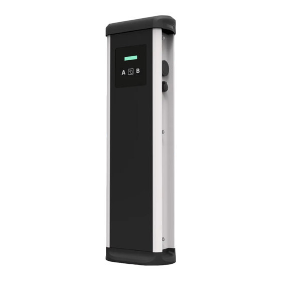
• Do not modify this unit. If modified, don’t close...). CIRCONTROL will reject responsibility and the warranty • Use only Circontrol supplied spare will be void. parts. • Comply strictly with electrical • Do not use this product if the safety regulations according to enclosure or the EV connector is your country. - Page 8 Smart Series User Manual 1 — Hat 4 — RFID Reader 7 — Key lock access 5 — Wall support 2 — LED Beacons 8 — Base 3 — Display LCD 6 — Plugs* (*) Plugs may vary depending on the model...
-
Page 9: Features
Features M A I N F E AT U R E S O F T H E U N I T Charge Point may not include elements of electrical protection. • Display: Information about the • Energy metering: Integrated status of the connectors and meter built is measuring power detailed data as kWh and duration and energy consumed by the EV... - Page 10 Smart Series User Manual Start Charging 1. The first step is to show the proximity card to the reader* Once done, the Led Beacon turns Blue and the Display shows the following sequence of messages: *If the proximity card reader is disabled, charge transaction starts automatically when a vehicle is detected.
-
Page 11: How To Use It
How to use it? Stop Charging 1. The first step is to show the proximity card to the reader* Once done, the Led Beacon turns Green and the Display shows the summary of the charge transaction: *If the proximity card reader is disabled, charge transaction stops automatically when a cable is disconnected from the vehicle. - Page 12 Smart Series User Manual Introduction The Charge Point can be configured and monitorized to establish preferences or specific setup using integrated Ethernet communication port allocated in the main controller device. What’s needed Before proceeding with the configuration, make sure all the following is...
-
Page 13: How To Configure It
How to configure it? Connection Charge Point is delivered with default network setting of “DHCP enabled”. It means that the charge station will try to obtain an IP address from a DHCP server available on the network. Connecting a PC directly with the Charge Point needs to be done with static IP address. - Page 14 Smart Series User Manual Setup webpage allows managing networking setup, upgrading devices and other options. To access the setup web page, open a web browser and enter the IP address previously configured. Dashboard Overview As a relevant information, the ‘Summary’ shows: •...
-
Page 15: Setup Webpage
Setup Webpage Devices Status As a relevant information, the ‘Devices Status’ shows: • Device name: Name of the devices inside the Charge Point Status: OK (online) / NOT OK (offline) •... - Page 16 Smart Series User Manual System Status The information shown in this section is basically relative to the state of the Control Board of the Charge Point This is necessary for the technical service staff but does not show any information regarding the external connection of the Charge Point or the charging session.
- Page 17 Modem Status When the cellular connection is successful, this section shows the public IP, the signal strength and other information related to the SIM Card. The following diagram shows an approximated range of signal strength that can be obtained depending on the location of the Charge Point: -50 dBm -80 dBm -90 dBm...
- Page 18 Smart Series User Manual Drivers The information shown in this section is regard to the drivers that the Charge Point needs in order to recognize the different devices inside the Charge Point, such as the meters, the Mode 3 controller, the RFID reader,...
- Page 19 Repository Sources The information shown in this section is basically related to the internal behavior of the Charge Point. This is necessary for the technical service staff but does not show any information regarding the external connection of the Charge Point or the charging session.
- Page 20 Smart Series User Manual System Logs The logs shown in this section are automatically produced by the Charge Point, it is a detailed list of the charging sessions, system performance, or user activities. This logs are created since Charge Point is powered On. Even if Charge...
-
Page 21: B Network
Network This section provides basic configuration of the network parameters. Clicking over the ‘Network’ tab, next image will appear. - Page 22 Smart Series User Manual Value Description Hostname Name of the Charge Point on the network •Local address: select this option if the OCPP central system is connected to the same private network than the Charge Point is already connected. It is assigned to the Ethernet Port.
-
Page 23: C Modem
Modem Before configuring the cellular communications, insert the SIM Card on the modem as shown: If the three LEDs are not on after inserting the SIM card, check the modem configuraton. - Page 24 Smart Series User Manual To configure the integrated modem, check this section to set the parameters provided by the SIM Card network operator. Value Description Access point name (Consult SIM Card network operator) User Credentials assigned to the APN...
-
Page 25: D Security
Security This section provides basic configuration of the security parameters. Avoiding unauthorised access to the Setup Webpage. All parameters are disabled from factory settings. Value Description ON: authentication enableb / OFF: authentication disabled Authentication User Name Password Username and Password authentication for Setup web page Repeat password Do not forget the credentials. -
Page 26: E Locale
Smart Series User Manual Locale This section allows to change the language of the Charge Point, choosing among several options. For availability of languages, please consult your local supplier. -
Page 27: F Time
Time This section allows setting the time and region time for the Charge Point. Value Description Time Zone Select the regional time for the Charge Point according to the location Time Current date and time of the Charge Point Primary NTP Server Synchronize the time through internet automatically Secondary NTP Server... -
Page 28: G Integrations
Smart Series User Manual Integrations This section allows to enable and disable OCPP service of the Charge Point. Both OCPP 1.5 and OCPP 1.6 are available on the last firmware version. For more information about the parameters and configuration,... -
Page 29: H Firmware
The Charge Point firmware can be upgraded remotely by clicking on the ‘Select File’ button. A window will pop up in order to choose the file, then click on ‘upload’. To obtain the latest firmware version please contact CIRCONTROL Post Sales Department. More information in ‘Need help?’ chapter. -
Page 30: I Configuration Update
‘Select File’ button. Intended ONLY for Service Staff to restore the Charge Point to default factory settings. A window will pop up in order to choose the file, then click on ‘upload’. To obtain the appropriate configuration file please contact CIRCONTROL Post Sales Department. More information in ‘Need help?’ chapter. - Page 32 Charge Point and a Central System. With this open protocol it is possible to connect any Central System with any Charge Point, regardless of the vendor. Follow next steps in order to configure OCPP 1.5 in the Circontrol Charge Points.
- Page 33 OCPP 1.5 Before starting Check following steps in order to ensure the correct function of OCPP 1.5: Go to the Setup Webpage > ‘Network’ tab Public Address Manager establishes where the Charge Point must obtain the public IP address in order to send it later to the backend. Different values can be selected in the ‘Address Type’...
- Page 34 Smart Series User Manual Go to the Setup Webpage > ‘Integrations’ tab Charge Point supports different versions of OCPP but only one can be enabled at the same time. Go back to setup web page and click on the ‘Integrations’ tab, choose the option selected under ‘Available integrations’...
-
Page 35: Ocpp
Configuration Go to the Setup Webpage > ‘Integrations’ tab Once OCPP 1.5 option is selected, a link appears allowing access to the OCPP configuration. Please, click on the link button as shown in the picture: New tabs are opened to show OCPP Settings. It can also be accessed directly typing: http://<IP>:8080/html/setup.html These tabs require a user identification: User: admin... - Page 36 Smart Series User Manual On the OCPP webpage, go to ‘Charge Box’ tab Check Charge Box Identity and the incoming ports according to the backend policies, please contact to the Central System to get the configuration parameters: Value Description...
- Page 37 Go to ‘Central system’ tab Allows the Charge Point to know where the central system is hosted to notify all the requests. Check Central System URL according to the backend policies, please contact to the Central System to get the configuration parameters: Value Description ID Tag Endianness...
- Page 38 Smart Series User Manual Go to ‘OCPP Settings’ tab Check OCPP Settings according to the backend policies, please contact to the Central System to get the configuration parameters: Before making any changes read following table and set each option according to your backend provider.
- Page 39 Value Description YES: local list of authorized users -> Enabled Use local white-list NO: local list of authorized users -> Disabled LOCAL: ID authorization has first place on the local white- -list. If the user does not exist locally, then in second place backend is asked to obtain the authorization.
- Page 40 Smart Series User Manual Value Description YES: Synchronization of date and time -> Enabled. NO: Synchronization of date and time -> Disabled. Use OCPP time synchronization *NOTE: Date and Time is sent from backend on each heartbeat response. YES: Compress messages between Charge point and backend ->...
- Page 41 Value Description YES: Stop existing charge transaction after response from backend (StartTransaction.conf) when user has already Stop charge if involved in another transaction. StartTransaction replies NO: Charge transaction does not stops even if backend ConcurrentTx rejects the user. (StartTransaction.conf) *NOTE: Set this option according to your backend system. YES: Charge point sends an authorization request before Require auth.
- Page 42 Smart Series User Manual Once done, please do not forget to save changes using ‘Save’ button in the upper right bar: Please, wait until the new configuration is being applied to the Charge Point. A message is displayed informing the progress:...
-
Page 43: D Checkup
Checkup After applying new settings, please go to next URL from Charge Point in order to check properly connection from the integration chosen: http://<IP>/services/cpi/log?app=ocpp1.5 Look especially for the following messages: If ‘CB boot notification: success’ appears then Charge Point is properly connected to the back-end. - Page 44 Charge Point and a Central System. With this open protocol it is possible to connect any Central System with any Charge Point, regardless of the vendor. Follow next steps in order to configure OCPP 1.6 in the Circontrol Charge Points.
-
Page 45: Ocpp 1.6
OCPP 1.6 Before starting Check following steps in order to ensure the correct function of OCPP 1.6: Go to the Setup Webpage > ‘Network’ tab Public Address Manager establishes where the Charge Point must obtain the public IP address in order to send it later to the backend. Different values can be selected in the ‘Address Type’... - Page 46 Smart Series User Manual Go to the Setup Webpage > ‘Integrations’ tab Charge Point supports different versions of OCPP but only one can be enabled at the same time. Go back to setup web page and click on the ‘Integrations’ tab, choose the option selected under ‘Available integrations’...
-
Page 47: C License Activation
If the Charge Point does not have the license applied, the following message pops up: To obtain the license file please contact CIRCONTROL Post Sales Department. More information in ‘Need help?’ chapter. The license can be applied by clicking on the ‘Select File’ button. - Page 48 Smart Series User Manual A window will pop up in order to choose the file, then click on ‘upload’.
-
Page 49: D Configuration
Configuration Go to the Setup Webpage > ‘Integrations’ tab Once OCPP 1.6 option is selected, a link appears allowing access to the OCPP configuration. Please, click on the link button as shown in the picture: New tabs are opened to show OCPP Settings. It can also be accessed directly typing: http://<IP>:8080/html/setup.html These tabs require a user identification: User: admin... - Page 50 Smart Series User Manual On the OCPP webpage, go to ‘Charge Box’ tab Check Charge Box Identity and the incoming ports according to the backend policies, please contact to the Central System to get the configuration parameters:...
- Page 51 Value Description Charge Point identifier Maximum size of the Authorization Cache, that autonomously Cache max. size maintains a record of previously presented identifiers that have been successfully authorized by the Central System. It can be viewed accessing to the following URL: http://<IP>:8080/services/cmd/dump_cache.xml YES: Synchronization of date and time ->...
- Page 52 Smart Series User Manual Go to ‘Central system’ tab Allows the Charge Point to know where the central system is hosted to notify all the requests. Check Central System URL according to the backend policies, please contact to the Central System to get the configuration parameters:...
- Page 53 Go to ‘OCPP Settings’ tab Check OCPP Settings according to the backend policies, please contact to the Central System to get the configuration parameters:...
- Page 54 Smart Series User Manual Value Description YES: maintain a local list of all presented identifiers that have Authorization cache enabled been successfully authorized by the Central System. NO: authorization for presented identifiers is requested directly to the Central System...
- Page 55 Value Description YES: Charge Transaction stops when the cable is disconnected Stop transaction when EV from the EV unplugged NO: Charge Transaction does not stop when the cable is disconnected from the EV; furthermore, if it is reconnected energy transfer is allowed again. It is required for the user to present the identifier in order to stop the Charge Transaction.
- Page 56 Smart Series User Manual Value Description Metervalue sample Number of seconds between MeterValue during an ongoing interval Charge Transaction. *NOTE: setting this value to 0 disables the MeterValue. Transaction Number of seconds between transaction message attempts. message retry *NOTE: setting this value to 0 disables the attempts.
-
Page 57: E Checkup
Once done, please do not forget to save changes using ‘Save’ button in the upper right bar: Checkup After applying new settings, please go to next URL from Charge Point in order to check properly connection from the integration chosen: http://<IP>/services/cpi/log?app=ocpp1.6 If ‘CB boot notification: success’... - Page 58 Point in order to monitor the real-time status. The main way to connect is using the CirCarLife client software (Supplied by Circontrol PS-Support staff) or you can download it from Circontrol Expert Area Webpage. NOTE: Java software needs to be installed on the computer in order to run the client software, please, download last version from: www.java.com...
-
Page 59: Monitoring
Monitoring... - Page 60 Smart Series User Manual DATA SPECIFICATIONS Light beacon RGB Colour indicator Enclosure rating IP44 / IK8 Enclosure material Aluminium & ABS Enclosure door Frontal key locked door Net weight 55Kg Dimensions (W x H x D) 450 x 1550 x 290 mm...
-
Page 61: Technical Data
Technical Data GENERAL DATA Touch screen 8" Display LCD Multi-language RFID reader ISO/IEC 14443 A Legic RFID reader ISO/IEC 14443 A+B (optional) ISO/IEC 18092 ECMA-340 ISO/IEC 15693 Legic Prime Meter MID Class 1 - EN50470-1/3 Ethernet 10/100BaseTX (TCP-IP) Embedded modem 4G LTE/3G/GPRS Cellular (optional) Modem 4G LTE/WiFi Hotspot/3G/GPRS Interface protocol... - Page 62 Smart Series User Manual...
-
Page 63: Need Help
Need help? In case of any query or if further information is required, please contact our Post-Sales Department. ps-support@circontrol.com circontrol.com (+34) 937 362 940 (+34) 937 362 941... - Page 64 CIRCONTROL EVOLVE SMART SERIES USER MANUAL A comprehensive guide on how to use and configure your Post and Wallbox eVolve. V2.0, April edition 2020 R214 CIRCONTROL S.A. - ALL RIGHTS RESERVED...
Need help?
Do you have a question about the eVolve Smart Series and is the answer not in the manual?
Questions and answers