Advertisement
Quick Links
Advertisement

Related Manuals for Circontrol Wallbox eHome Series


Summary of Contents for Circontrol Wallbox eHome Series
- Page 1 Wallbox eHome Series Installation Manual...
- Page 2 C O P Y R I G H T I N F O R M AT I O N This document is copyrighted, 2021 by Circontrol, S.A. All rights are reserved. Circontrol, S.A. reserves the right to make improvements to the products described in this manual at any time without notice.
-
Page 3: Table Of Contents
Here’s your guide to install eHome So, hello! Installation Before the installation Technical Data Overview Modbus Register Map Dimensions Need help? - Page 4 WallBox eHome Series Installation Manual...
-
Page 5: So, Hello
So, hello! This manual provides commissioning information about Wallbox eHome series, which has been designed and tested to allow electric vehicle charging according to IEC 61851-1:2017 This document has different sections such as step-by-step installation procedure and technical data. THE FOLLOWING SYMBOLS ARE USED FOR IMPORTANT... - Page 6 WallBox eHome Series Installation Manual I M P O R TA N T S A F E T Y I N S T R U C T I O N S Read carefully all the instructions before starting in order to ensure properly installation of the charge point.
-
Page 7: Before The Installation
Before the installation E L E C T R I C A L W I R I N G C O N S I D E R AT I O N S Take into consideration this section before start wiring connections of the charge point. - Page 8 Type 1 or Type 2 connector or connecting the EV cable into the charger socket Type 2. What’s included: Installation Manual Charge Point The wallbox eHome Series can includes the RS-485, with interface Modbus in order to be managed by an external master device through it.
-
Page 9: Overview
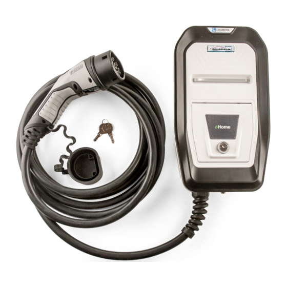
Overview Circontrol Logo Frame Status RGB LED bar Socket Front cover Protections and Meter Door Cable + Connector. - Page 10 WallBox eHome Series Installation Manual Measures in mm...
-
Page 11: Dimensions
Dimensions Measures in mm... - Page 12 WallBox eHome Series Installation Manual Material: Screws, sealing washers and plastic anchors are not included. The installation kit has been tested on a concrete wall. For the unit to be securely fixed in such conditions, it is recommended to use: 3 x Inox A2 wall screws: Ø3x45...
-
Page 13: Installation
Installation S PAC E R E Q U I R E M E N T S When installing the unit, some space shall be reserved for usability, maintenance and safety reasons. Please comply accordingly to your country specifications. The next picture shows the recommended minimum distances: Measures in mm MIn. - Page 14 WallBox eHome Series Installation Manual O P E N I N G T H E U N I T 1. Remove the screw at the bottom of the box. 2. Using a screw driver, put it into the indicated marks, at the bottom of the box, and starting removing the frame doing click at the bottom.
- Page 15 3. Grabbing the frame with the hand by the lower part, pull and take it off totally, from the bottom to the top To make it easier help yourself with the screw driver while pulling the frame off. 4. Remove the six screws of the front part by using a screw driver and take out the front part of the enclosure.
- Page 16 WallBox eHome Series Installation Manual P O W E R S U P P LY L I N E A N D DATA C A B L E I N S E R T I O N There are two possibilities to insert the electric wires or electric pipe: a) Breaking out the cable insertion opening on the rear of the housing.
- Page 17 Do not make any other holes on the enclosure. Use only the marked cable insertion openings to install the required electric pipes.Install always double membrane seals to ensure IP protection of the charging point. Be careful of not damaging any of the inside components when breaking out the rear cable insertion opening.
- Page 18 WallBox eHome Series Installation Manual P O S I T I O N I N G Make holes for fastener screws. Tap drill M 6 Min. 600- / Max. 1200 Measures in mm Front view 1. Mark 3 holes taking into account the picture measurements (also written on the rear face of the box).
- Page 19 F I X I N G 1. Use a screwdriver to fix the Charge Point on the wall (recommended screw dimensions: 3x45mm) 2. Use only the Charge Point holes indicated in the above picture to fix the Charge Point on the wall. Do not make any other holes on the housing; otherwise water can enter the Charge Point when it rains.
- Page 20 WallBox eHome Series Installation Manual E L E C T R I C A L I N S TA L L AT I O N Depending on the model, it is necessary to install a Miniature Circuit Breaker (MCB) and a Residual Current Device (RCD) externally to protecting the power line.
- Page 21 P O W E R S U P P LY L I N E C O N N E C T I O N Perform the 230 VAC Single-phase or 400 VAC Three-phase connections as shown in the picture below. Do not forget to connect the ground cable (PE) to its corresponding terminal.
- Page 22 WallBox eHome Series Installation Manual Home BeON Home BeON is an optional device that optimises the charge. Analysing the total current consumption in residential facilities, Home BeON manages the remaining current for the Charge Point, avoiding any tripping on the Main Circuit. Please, note that this accessory is only available for single phase Charge Points.
- Page 23 Remote control function Remote control function is a potential free contact which allows the remote start and stop of a charge transaction. This remote control function is disabled by default, by means of a jumper (as shown in the picture below).
- Page 24 WallBox eHome Series Installation Manual Data Modbus RS485 Connection Perform the Modbus RS485 data connection in the terminal shown in the picture below. Notes: The Modbus RS485 provide the following terminals (A+, S, B-) Do not forget to connect the ground cable (S Terminal) and link to its...
- Page 25 Wallbox eHome Series dwe are going to install. On the following table is shown the different values available for this current limit selector:...
- Page 26 WallBox eHome Series Installation Manual C L O S I N G T H E C H A R G E P O I N T Screw the 6 bolts from the front cover in order to close the Charge Point...
- Page 27 V E R I F I C AT I O N 1 — P O W E R I N P U T Before proceeding, make sure voltage is present in the terminal blocks. For Three-Phase models pay special attention to Neutral Cable. 2 —...
- Page 28 WallBox eHome Series Installation Manual AC INPUT CCL-eHome T1C32 / T2C32 / T2S32 1P + N + PE AC Power supply CCL-eHome TRI T2S16 / TRI T2C16 3P + N + PE CCL-eHome T1C32 / T2C32 / T2S32 230 VAC +/- 10%...
-
Page 29: Technical Data
Technical Data GENERAL Enclosure rating IP54 / IK10 Enclosure material ABS-PCV0 Operating temperature -5ºC to +45ºC Operating humidity To 95% RH Non-condensing Net weight OPTIONAL FEATURES Extended operating temperature (Optional Heater) -30ºC…+45ºC Protection shutter (only available for Type 2 connectors) RS485 Opcional Module Protections may not be included in the charge point, at this point, protections with the same characteristics, shall be placed... - Page 30 WallBox eHome Series Installation Manual EHOME RS485 (v1.0 130221) Address Mode Size Register Name Values Description Communications 0x0000 (16bits) AddDevice 1...254 Peripherical Address 0x0001 (16bits) ConfigComs 0...5 Communication Configuration Mode 3 Charge 0x000A (16bits) Proximity (InRCC) Cable Vehicle intenity 0x000B...
-
Page 31: Modbus Register Map
Modbus register map EHOME RS485 (v1.0 130221) Address Mode Size Register Name Values Description BeOn 0x0032 (16bits) LineLoad_BeOn_AC 0x0033 (16bits) TimerBeOn Perormance Time Base "Tick". 0x0034 (16bits) CurrentSlope_BeOn_AC 0x0035 (16bits) SetPointBeOn_AC Device Identification 0x03E8 (16bits) HW & FW version 0xHHSS HH: Hardware version SS: Software version 0x03E9... - Page 32 WallBox eHome Series Installation Manual...
-
Page 33: Need Help
Need help? In case of any query or need further information, please contact our Post-Sales Department support@circontrol.com www.circontrol.com (+34) 937 362 940 (+34) 937 362 941... - Page 34 WallBox eHome Series Installation Manual...
- Page 35 Notes...
- Page 36 WallBox eHome Series Installation Manual CIRCONTROL WALLBOX eHome Series INSTALLATION MANUAL A comprehensive guide on how to install and verify your charge point V1. 12 July 2021 Scan me to download the User Manual R381 CIRCONTROL S.A. - ALL RIGHTS RESERVED...
Need help?
Do you have a question about the Wallbox eHome Series and is the answer not in the manual?
Questions and answers