Circontrol Post eVolve Series Installation Manual
Hide thumbs
Also See for Post eVolve Series:
- Installation manual (24 pages) ,
- Installation manual (24 pages) ,
- Installation manual (32 pages)
Advertisement
Advertisement

Related Manuals for Circontrol Post eVolve Series


Summary of Contents for Circontrol Post eVolve Series
- Page 1 Post eVolve Series Installation Manual...
- Page 2 C O P Y R I G H T I N F O R M AT I O N This document is copyrighted, 2017 by Circontrol, S.A. All rights are reserved. Circontrol, S.A. reserves the right to make improvements to the products described in this manual at any time without notice.
-
Page 3: Table Of Contents
Here’s your guide to install eVolve. 1 — So, hello! 4 — Installation 2 — Before the 5 — Technical installation Data 3 — Dimensions 6 — Need Help? and Overview... - Page 4 Post eVolve Series Installation Manual...
-
Page 5: So, Hello
So, hello! This manual provides commissioning information, which has been designed and tested to allow electric vehicle charging, specified in IEC 61851. This document has different sections such as step-by-step installation procedure and technical data. THE FOLLOWING SYMBOLS ARE USED FOR IMPORTANT SAFETY INFORMATION IN THIS DOCUMENT ELECTRIC RISK Take precautions to make the electrical connection inside the... - Page 6 Post eVolve Series Installation Manual I M P O R TA N T S A F E T Y I N S T R U C T I O N S Read carefully all the instructions before starting in or- der to ensure properly installation of the charge point.
-
Page 7: Before The Installation
Before the installation E L E C T R I C A L W I R I N G C O N S I D E R AT I O N S Take into consideration this section before start wiring connections of the charge point. - Page 8 Post eVolve Series Installation Manual What’ s included: Charge Point Installation CirCarLife RFID Manual Mifare Card eVolve Post Key Foundation Kit...
- Page 9 Minimum Distances When installing the unit, respect the minimum distances space for maintenance and safety reasons. Please comply accordingly to your country specifications. The next picture shows how it should be installed. • Do not install near areas where water or fluids can penetrate into the unit. •...
- Page 10 Post eVolve Series Installation Manual Foundation Kit: Nuts M16 Template Foundation bolt...
- Page 11 Foundation • Place the foundation bolts into the template using provided nuts with the help of a 24mm open-end wrench. • Once the kit is assembled, it must be placed in the ground taking into consideration the following measures. Side view Front view Measures in mm Note: In the event of any doubt about the terrain regarding the installation of this...
- Page 12 Post eVolve Series Installation Manual 1544 1351 Measures in mm...
-
Page 13: Dimensions And Overview
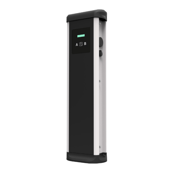
Dimensions and Overview 1 — Hat 4 — Plugs** 2 — LED Beacons 5 — Key lock access 3 — Display & RFID Reader* 6 — Base (*) Only Smart Series (**) Plugs may vary depending on the model... - Page 14 Post eVolve Series Installation Manual Opening Use provided key in order to open the unit:...
-
Page 15: Installation
Installation Positioning Remove the template nuts before proceeding. Place the charge point through the four foundation bolts. - Page 16 Post eVolve Series Installation Manual Fixation Firmly tighten the 4 nuts using a 24mm open-end wrench.
- Page 17 Metal plate • It is recommended to install a cable glands (not supplied) in pre-holes position. • Assembly metal plate using the 4 supplied screws as shown below:...
- Page 18 Post eVolve Series Installation Manual Wiring SINGLE-PHASE CHARGE POINT THREE-PHASE CHARGE POINT Connect to the 230VAC. Connect to the 400VAC. • • • If the Power Supply is Single- Phase, connect L1 and N. • Make sure all screws are securely tightened •...
- Page 19 Verification 1 — P O W E R I N P U T Before proceeding, make sure voltage is present in the terminal blocks. For Three-Phase models pay special attention to Neutral Cable. 2 — M A I N T E N A N C E M O D E Pull outward the Tamper Switch located in the lower half of the Charge Point.
- Page 20 Post eVolve Series Installation Manual GENERAL DATA Display* LCD Multi-language Light beacon RGB Colour indicator RFID reader* ISO / IEC 14443A/B MIFARE Classic/Desfire EV1 ISO 18092 / ECMA-340 NFC 13.56MHz MECHANICAL DATA Enclosure rating IP54 / IK10 Enclosure material Aluminium & ABS...
-
Page 21: Technical Data
Technical Data ELECTRICAL DATA Power supply 1P+N+PE / 3P+N+PE Input voltage 230VAC+/- 10% / 400VAC+/-10% Frequency 50Hz / 60Hz Overcurrent protection MCB (curve C) Safety protection RCD Type A (30mA) / Type B* Surge protection* Transient surge protector IEC 61643-1 (Class II) MINIMUM OUTPUT OUTPUT... - Page 22 Post eVolve Series Installation Manual...
-
Page 23: Need Help
Need help? In case of any query or need further information, please contact our Post-Sales Department ps-support@circontrol.com circontrol.com (+34) 937 362 940 (+34) 937 362 941... - Page 24 CIRCONTROL eVOLVE INSTALLATION MANUAL A comprehensive guide on how to install and verify your eVolve. V2.1, August edition 2017 Rev.40 CIRCONTROL S.A. - ALL RIGHTS RESERVED...
Need help?
Do you have a question about the Post eVolve Series and is the answer not in the manual?
Questions and answers