Table of Contents
Advertisement
Advertisement
Table of Contents

Related Manuals for Globalstar ST100


Summary of Contents for Globalstar ST100
- Page 1 ST100 USER MANUAL 8545-0194-01 v1.0...
- Page 2 Distribution Statements: GLOBALSTAR CONFIDENTIAL AND PROPRIETARY INFORMATION – All data and information contained in this document are confidential and proprietary to Globalstar, Inc. Information and instructions contained in this publication anticipate the user possesses and applies the knowledge, training, and experience commensurate with requirements to meet prerequisite certification.
-
Page 3: Table Of Contents
1.2.2. External References ...........................1 1.3. DESCRIPTION .............................1 1.4. CERTIFICATIONS ............................2 2. APPLICATION ........................3 2.1. THEORY OF OPERATION FOR GLOBALSTAR COMMERCIAL IoT ...............3 2.2. ST100 FUNCTIONAL STATES ........................5 2.2.1. Pre-operational states .........................5 2.2.1.1. Configuration mode .......................5 2.2.1.2. Staged for activation mode ....................5 2.2.1.3. - Page 4 8545-0194-01 v1.0 4. APPLICATION PROGRAMMING INTERFACE ................15 4.1. ASCII COMMAND LIST AND FORMAT ......................17 4.1.1. ASCII Format...........................17 4.1.1.1. “?” ...........................17 4.1.1.2. “abort” ..........................17 4.1.1.3. “auth” ..........................18 4.1.1.4. “bursts”..........................18 4.1.1.5. “ctrack”..........................18 4.1.1.6. “data” ..........................18 4.1.1.7. “dldump” ..........................19 4.1.1.8. “esn” ..........................19 4.1.1.9.
- Page 5 4.2.2.34. “Turn Off GPS” command ....................53 4.2.2.35. “Turn On GPS Pass-through” command ................54 4.2.2.36. “Turn Off GPS Pass-through” command ................55 4.3. ST100 BOARD SELF-TEST COMMAND ......................56 4.4. HEALTH STATUS MESSAGING ........................57 4.5. BOOTLOADING. FIELD UPDATE OF DEVICE FIRMWARE ................58 4.5.1. Nordic Nrf52832 Firmware Update Via Bootloader (“Buttonless” DFU) ..........58 4.5.2.
- Page 6 6.1. POWER REQUIREMENTS FOR AN EXTERNAL ANTENNA TO MAINTAIN SPECIFIED EIRP .......72 6.2. GPS / SATELLITE ANTENNA TUNING ......................73 6.3. BLUETOOTH ANTENNA TUNING ........................78 7. GLOBALSTAR CERTIFICATION PROCESS FOR CUSTOMER PRODUCTS ........79 8. GENERAL WARNINGS ......................80 9. REGULATORY ........................81...
- Page 7 Table 6 - DTP401525, 3.7V, 110mAh, Li-Polymer Battery ..................12 Table 7 - Operating Conditions ..........................14 Table 8 - Operating Modes & Standby Currents ......................38 Table 9 - ST100 Test Modes ...........................69 Table 10 - ST100 Channels ............................69 Table 11 - External Antenna Power Requirements .....................72 LIST OF FIGURES Figure 1 - Board Physical Dimensions ........................2...
-
Page 8: Introduction
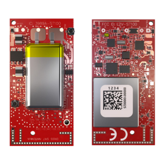
1.3. DESCRIPTION The ST100 board is a simplex Satellite transmitter designed to send small packets of user defined data to a network of low earth orbiting (LEO) satellites using the Globalstar commercial IoT network. The received data is then forwarded to a user defined network interface that may be in the form of an FTP host or HTTP host where the user will interpret the data for further processing. -
Page 9: Certifications
Under VAR setup and configuration, and normal use by the end user, communication with the device is via a Bluetooth Low Energy (BLE) GATT/Modem interface with a mixture of ASCII and binary command/query protocols. The ST100 PCB weighs ~6.2g (with shield, no battery, no solar panel), with the dimensions shown below: FIGURE 1 - BOARD PHYSICAL DIMENSIONS 1.4. -
Page 10: Application
2.1. THEORY OF OPERATION FOR GLOBALSTAR COMMERCIAL IoT The ST100 Board operates on the Globalstar LEO satellite network. LEO (Low Earth Orbit) means that there are a number of satellites in low earth orbit that constantly orbit the planet and can communicate with Globalstar devices that are within range of its current position. - Page 11 Messages are composed of 1 or more 9-byte payloads. The user application may send a message via the Bluetooth Low Energy interface to the ST100 board from 1 to 144 bytes in length. The ST100 board will break the message into 9 byte packets. A 144 byte message would be divided into 16 packets.
-
Page 12: St100 Functional States
• Optional: A low battery report rate. This is the report rate the ST100 drops to when the battery voltage is below 3.6 volts. The unit is shipped from the factory with this value set to 24 hours (one transmission per day). If the VAR desires a different value here, it may be set via the “slbatrate”... -
Page 13: Activation Mode - Line Powered, Alternative Forced Activation
If this command is issued, the GPS fix step below will commence when line power is applied. If you are unable to activate the ST100 (due to low sunlight conditions) bypass the activation algorithm to instantly activate the unit using the following steps: Note, this does not mean that the unit will start transmitting even if the battery is low. -
Page 14: End Of Life
Once the unit has entered end of life mode, it will respond to simple queries, such as a query for its version number or tracking state (which will be “none”), but it will NAK any command that might cause it to transmit over the Globalstar network, such as commands to put it back into a track mode or to send a custom message. -
Page 15: Handling Of Electrostatic Sensitive Devices
If the internal ST100 Bluetooth and/or GPS/Satellite antennas are used, care should be taken as to what is placed above, below, and around the short edges of the PCB. The short edges are where the ST100 internal antennas are located. For best performance, the ST100 should have an unobstructed view of the sky, either outdoors or in a glass-enclosed area such as a vehicle dashboard. -
Page 16: External Connections
2.10.2. BATTERY The ST100 has terminals on the PCB where a battery can be soldered to. The user / installer should carefully note the location of the positive and negative terminals marked on the PCB and solder the battery accordingly. It will be up to the user / installer to verify the power requirements (see Table 7 - Operating Conditions). -
Page 17: Solar Panel
2.10.3. SOLAR PANEL The ST100 has terminals on the PCB where a solar panel can be soldered to. The user/installer should carefully note the location of the positive and negative terminals marked on the PCB and solder the solder panel accordingly. It will be up to the user/installer to verify the solar power requirements (see Table 7 - Operating Conditions: Power Requirements). -
Page 18: Pin Connector
8545-0194-01 v1.0 Notes: 1. This list is not a complete list of acceptable solar panels. These are panels that Globalstar has identified and tested as acceptable. 2. The VAR/installer should review the pairing of solar panel / battery and determine if the solar panel is adequate for use with the selected battery. -
Page 19: Power Performance Characteristics
2.11. POWER PERFORMANCE CHARACTERISTICS The ST100 battery performance heavily depends on the amount of GPS and Satellite Transmitter usage. Below are some examples of battery performance for select battery sizes and track modes. -
Page 20: Accelerometer
Motion Activated Track”. This will cause the ASIC to use the accelerometer for motion detection. Custom Nordic firmware written by the VAR using the Globalstar ST100 SDK may also be used to invoke this special track mode. All interface to the ASIC processor from such custom code is via the binary serial packed commands described in section 4.2. -
Page 21: General Specifications
6. Both the 0.75V and 50mW requirements must be met on the solar input for charging a depleted battery. 7. The maximum current the solar charger chip on the ST100 board will accept is about 100mA, regardless of solar panel size. -
Page 22: Application Programming Interface
4. APPLICATION PROGRAMMING INTERFACE The ST100 Board provides a Bluetooth Low Energy (BLE) GATT/Modem interface for controlling the operation of the device. Commands are used to send information over the commercial IoT network, operate the GPS engine, and monitor the internal operation of the device. - Page 23 8545-0194-01 v1.0 4. Connect to the device. 5. Press the Diagnostic Menu icon. 6. Enter commands. ST100 User Manual v1 Confidential & Proprietary Information...
-
Page 24: Ascii Command List And Format
4.1. ASCII COMMAND LIST AND FORMAT The ST100 Board accepts a set of ASCII commands to query the board for status, and to cause it to perform various commands. Commands take the form of a “keyword” and a variable number of arguments, in the same form of command line arguments in a Windows or Linux command prompt window. -
Page 25: Auth
The commands requiring “auth” are unlocked for 30 seconds after sending the auth command. Sending the commands multiple times (e. g. “raw”) DOES NOT “bump out” the 30 second timer. However, once the user has kicked the ST100 board into binary passthrough mode, the “auth” will expire concurrently with the binary passthrough expiry. -
Page 26: Dldump
(Time to Full) TTE: (Time To Empty) 4.1.1.10. “firmware” Returns the Aggregate board firmware version, and individual processor firmware versions. Command: firmware Arguments: None Example: firmware Example response: Firmware version: 1.0.0 (010000-010000) ST100 User Manual v1 Confidential & Proprietary Information... -
Page 27: Gadgdata
Example response: Size: 4 Value: 1595867014 NOTE: Using this command at high frequency or with a low tracking interval may cause GPS data logging inconsistencies. 4.1.1.14. “ghwdetail” Get the HW details of the ST100 board. Command: ghwdetail Arguments: None... -
Page 28: Glbatrate
8545-0194-01 v1.0 4.1.1.15. “glbatrate” Get the low battery transmission rate of ST100. Command: glbatrate Arguments: None Example: glbatrate Example response: Low battery rate is 0005 4.1.1.16. “glgps” Get latest GPS frame from the Nordic processor. Command: glgps Arguments: None Example:... -
Page 29: Gpspgdump
Timestamp 2: End time in UNIX 10 digit format Example: gpstsdump 1 1595869702 1595879702 Example response: GPS frames are transmitted over the BLE interface. Only the GPS frames that are within the timestamp range will be transmitted. ST100 User Manual v1 Confidential & Proprietary Information... -
Page 30: Gtrackst
Get UID of ST100. Command: guid Arguments: None Example: guid Example response: UID: 4294967294 NOTE: The UID is the unique identifier for the ST100 device. 4.1.1.23. “hardware” Returns the ST100 Board hardware version. Command: hardware Arguments: None Example: hardware Example response: Hardware Version: 1.0.0-F0... -
Page 31: Qpeek
This allows any command in the “Binary Serial Packet Commands” section to be sent to the ASIC. It is this command that implements the simplest form of the “STINGR with Bluetooth” function of the ST100 tag. The response is the Hex string returned as an acknowledgement from the ASIC. The example above is an ESN query. -
Page 32: Runpost
The correct Globalstar Simplex channel is dictated by RAS (Radio Astronomy Site) avoidance and by a “geofrequency” channel map. Whenever the ST100 board obtains a fix, it sets the channel based on these criteria. If a user uses the product to send “raw”... -
Page 33: Sgactskip 0
8545-0194-01 v1.0 4.1.1.31. “sgactskip” Bypass or reinstate the activation algorithm of ST100. Mostly used for line powered devices. Command: sgactskip Arguments: Set/Get flag: “0” gets the current skip activation state “1” sets the current skip activation state Skip activation state: Only valid when set/get flags is set to “1”... -
Page 34: Sgblepar
Transmit power possible values (in dBm): Example1: sgblepar 0 Example1 response: Adv Interval: 7 TX power: 0 Example2: sgblepar 1 1 4 Example2 response: BLE parameters updated. Adv Interval: 1 TX power: 4 ST100 User Manual v1 Confidential & Proprietary Information... -
Page 35: Sghltint
Logging Mode: 1 Logging Overflow status: 1 Example2: sglogpar 1 1 1 Example2 response: Logging Mode: 1 Logging Overflow status: 1 Wrote logging parameters to flash (When set/get flag is set to “1”) ST100 User Manual v1 Confidential & Proprietary Information... -
Page 36: Sgvltlmts 0
8545-0194-01 v1.0 4.1.1.37. “sgvltlmts” Set the low battery voltage threshold of the ST100. Command: sgvltlmts Arguments: Set/Get flag: “0” gets the logging parameters “1” sets the logging parameters Example: sgvltlmts 0 Example response: Low battery threshold: 3.60, Hibernation threshold: 3.40 4.1.1.38. -
Page 37: Binary Serial Packet Commands
CLSB and CMSB are omitted when using the RAW command. Length must still be specified to include them, however. • If an improperly formatted command is received, the ST100 BOARD will return a NAK response: AA 05 FF A1 CB ST100 User Manual v1 Confidential &... -
Page 38: Send Data (0X00)
8545-0194-01 v1.0 4.2.2.1. Send Data (0x00) The Send Data command requests the ST100 board to send from 1 to 144 data bytes over the Globalstar Simplex network. 0x00 LEADER PAYLOAD 1 PAYLOAD 2 PAYLOAD 3 PAYLOAD N CRC1 CRC2 CLSB... -
Page 39: Query Bursts Remaining (0X04)
8545-0194-01 v1.0 4.2.2.4. Query Bursts Remaining (0x04) The Query Bursts Remaining command requests the ST100 BOARD to return the current number of bursts remaining the current message transmit sequence over the Globalstar commercial IoT network. 0x04 LEADER CRC1 CRC2 Command:... -
Page 40: Query Setup (0X07)
0x18 = 24, 24 x 5 = 120 seconds • Maximum Burst Interval: 0x30 = 48, 48 x 5 = 240 seconds 4.2.2.7. Query Setup (0x07) The Query Setup command requests the ST100 BOARD to return the current setup parameters. 0x07 LEADER CRC1 CRC2... -
Page 41: Query Hardware Version (0X09)
0x18 = 24, 24 x 5 = 120 seconds • Maximum Burst Interval: 0x30 = 48, 48 x 5 = 240 seconds 4.2.2.8. Query Hardware Version (0x09) The Query Hardware Version command requests the ST100 BOARD to return the current hardware version information. 0x09 LEADER CRC1 CRC2 Command:... -
Page 42: Set Gps Timeout Command
GPS timeout value in seconds 0 - 15 4.2.2.11. “SPOT GEN3 emulation. The ST100 board has the ability to emulate the tracking and messaging modes of a SPOT GEN3 device for particular applications. ST100 User Manual v1 Confidential & Proprietary Information... -
Page 43: Special Consideration For "Byte 7" In The Next Several Commands
30 minutes, a single transmission will be sent per interval. If the interval is 40 minutes or greater, the ST100 board will randomize the start of each burst by +- 10 minutes around the nominal. For example, if a track mode with an interval of 1 hour is started at 12:00, the next burst position report will begin randomly between 12:50 and 1:10, the one after that will begin between 1:50 and 2:10, etc. - Page 44 2B4856 Where: is the 24-bit latitude 30.433051586151 (North) BFF032 is the 24-bit longitude -90.086817741394 (West) See section 4.6: “24 bit location format” for documentation of the encoding/decoding of Globalstar on-air location data. ST100 User Manual v1 Confidential & Proprietary Information...
-
Page 45: Proprietary Motion Activated Track" Command
Table 7. If the interval is 40 minutes or greater, the ST100 board will randomize the start of each burst by +- 10 minutes around the nominal. For example, if a track mode with an interval of 1 hour is started at 12:00, the next burst position report will begin randomly between 12:50 and 1:10, the one after that will begin between 1:50 and 2:10, etc. -
Page 46: Update Proprietary Track Data" Command
24-bit longitude -90.086817741394 (West) See section 4.6: “24 bit location format” for documentation of the encoding/decoding of Globalstar on-air location data. 4.2.2.15. “Update Proprietary Track Data” command This command is used to change the user programmable data in a proprietary track message. If a proprietary track session is not in progress, it is ACK’d but will do nothing. -
Page 47: Cancel Proprietary Track/Proprietary Motion Activated Track" Command
Always a value of 0xAA 0 - 7 Length 0 - 7 Command Code 0x32 = cancel proprietary track 0 - 15 LEADER CRC1 CRC2 Example Command: AA 05 32 48 D6 ST100 User Manual v1 Confidential & Proprietary Information... -
Page 48: Proprietary Track Status Query
NOTE: If the upper nibble of the Byte 7 value is 0xF, in other words if the “Byte 7 value & 0xF0 = 0xF0, the upper nibble of byte 7 is being populated with ST100 Status flags (See status flags section) NOTE 2: If the device is NOT in track mode, bytes 4 - 9 will all be populated with 0's. -
Page 49: Tracking Statistics Query
This holds the total messages transmitted since the track mode began. It will be a total of the 15-16 0 - 15 Total messages in mode scheduled track messages and the interleaved messages. 17-18 0 - 15 ST100 User Manual v1 Confidential & Proprietary Information... -
Page 50: Gps Statistics Query
3 = 3D fix and Globalstar “fix confidence” level reached. NOTE: Since the GPS subsystem is switched off as soon as the Globalstar Fix Confidence level is reached in normal operation, it will be rare to catch a “3” in this field. -
Page 51: Transmitter Statistics Query
Always a value of 0xAA 0 - 7 Length 0x06 0 - 7 Command Code 0x86 = Set Accelerometer On Off 0x00 = Off 0 - 7 On or off 0x01 = On 0 - 15 ST100 User Manual v1 Confidential & Proprietary Information... -
Page 52: Accelerometer On/Off Query
This command is used to initiate a redundant burst message (as setup in STX configuration). Bytes 1 – 6 of the first packet of the message shall contain latitude and longitude in standard Globalstar 24-bit format. Since each on-air message must be a multiple of 9 bytes, the message will contain up to 16 9-byte packets depending on the size of the payload. - Page 53 2B485D Where: is the 24-bit latitude 30.433126688004 (North) BFF02E is the 24-bit longitude -90.086903572083 (West) See section 4.6: “24 bit location format” for documentation of the encoding/decoding of Globalstar on-air location data. ST100 User Manual v1 Confidential & Proprietary Information...
-
Page 54: Query Location Command
Will contain the response CRC Command: AA 05 25 76 B2 Response: AA 0C 25 2B 48 5B BF F0 2B 00 2E A1 Latitude = 0x2B485B (30.4331), Longitude = 0xBFF02B (-90.0870) ST100 User Manual v1 Confidential & Proprietary Information... -
Page 55: Set Lifetime Command
Lifetime is set for 18 months and unit gets its first fix after setting the lifetime on Mar. 31, 2020: Last day of operation will be Sep. 30, 2021. Beginning Oct. 1, 2021, unit will be shut down. ST100 User Manual v1 Confidential & Proprietary Information... -
Page 56: Query Lifetime Status Command
This command will not be NAK’d for values < 2 but setting this “minimum” value to less than 2 shall simply enforce the absolute minimum of 2. The factory value for this shall be “0”. ST100 User Manual v1 Confidential & Proprietary Information... -
Page 57: Query Minimum Track Rate
Always a value of 0xAA 0 - 7 Length 0x07 0 - 7 Command Code 0x85 = Query minimum track rate 0 - 15 Rate Rate in minutes, MSB first 0 - 15 ST100 User Manual v1 Confidential & Proprietary Information... -
Page 58: Suspend/Unsuspend Command
0x00 = Full Suspend stop tracking messages completely 0 - 7 Mode argument 0x01 = Partial suspend reduce tracking rate to low battery rate 0x02 = Unsuspend. Track at normal tracking rate 0 - 15 ST100 User Manual v1 Confidential & Proprietary Information... -
Page 59: Set Low Battery Rate Command
Always a value of 0xAA 0 - 7 Length 0x07 0 - 7 Command Code 0x83 = Query low battery track rate 0 - 15 Rate Rate in minutes, MSB first 0 - 15 ST100 User Manual v1 Confidential & Proprietary Information... -
Page 60: Turn On Gps" Command
0 - 7 Command Code 0xFD 0 - 7 Sub Command Code 0x22 (Turn Off GPS) 0 - 15 Command: AA 06 FD 22 F4 9A Response: AA 05 FD B3 E8 ST100 User Manual v1 Confidential & Proprietary Information... -
Page 61: Turn On Gps Pass-Through" Command
NOTE: Depending on GPS engine configuration and status of the fix, all message types shown here may or may not be present. For example, the ST100 board is shipped with its GPS engine configured to obtain location using both GPS and GLONASS constellations. -
Page 62: Turn Off Gps Pass-Through" Command
0 - 7 Command Code 0xFD 0 - 7 Sub Command Code 0x20 (Turn Off GPS Pass-through) 0 - 15 AA 06 FD 20 E6 B9 Command: AA 05 FD B3 E8 Response: ST100 User Manual v1 Confidential & Proprietary Information... -
Page 63: St100 Board Self-Test Command
4.3. ST100 BOARD SELF-TEST COMMAND This command is used to initiate an internal self-test of the ST100 BOARD. When this command is received by the ST100 board, there will be a 2 - 5 second delay before the response is returned (self-test in progress). -
Page 64: Health Status Messaging
Bit 6: 0 = Transmitter OK; 1 = Fault. Set to 1 if an ASIC hardware error is detected. tem Fault Line Powered Bit 7: Reserved. Not used in the ST100. FW Version Byte 2: Major FW , Byte 3: Minor FW, Byte 4: Patch FW Version. -
Page 65: Bootloading. Field Update Of Device Firmware
The Nordic DFU app for Android or IOS can be used to update the firmware. It is essential that any custom firmware written by an OEM or VAR include the DFU library, provided with the Globalstar ST100 SDK, to support this functionality. -
Page 66: 0X61 "Flash One Line
0x61 0 - 7 Processor Number Must be 0 for the ST100 Board ASIC 0 - 7 Byte Count The “byte count” field (the first 2-digit hex number) of the Intel Hex Record line goes here (as a binary value). -
Page 67: 0X62 "Enter Application
0x00 = OK and done. (This is the response to End of File when loaded code has passed acceptance tests. 0xF0 = Address outside of application memory range. (In the ST100 board, this code is also returned if “processor number” is not 0.) 0xFF = Message format error or unknown error. -
Page 68: 0X63 "Status Query
Leader Always a value of 0xAA 0 - 7 Length 0x06 0 - 7 Command 0x63 0x00 = Application running 0 - 7 Response Code 0x05 = Bootloader running 0 - 15 ST100 User Manual v1 Confidential & Proprietary Information... -
Page 69: Jtag Programming Kit
ST100 board and a JTAG programming unit (such as the Segger Programmer). The programming kit allows a user to program the ST100's Nordic processor at a low level without the bootloader. Reference Globalstar document 8545-0223-01 ST100 Manual Upgrade Procedure for details. It is most strongly recommended that if this method is used, that a combined image, with application and bootloader merged, be loaded so that the device remains field-upgradable later. - Page 70 CRC for a message and update the message CRC unsigned short crc = crc16_lsb(msg, msg [1]- 2); msg [msg [1]- 2] = (unsigned char) (crc&0xFF); msg [msg [1]- 1] = (unsigned char) (crc>>8); ST100 User Manual v1 Confidential & Proprietary Information...
- Page 71 USAGE: calculate the CRC for a message and update the message CRC msg[]; int len; char crc = crc16_lsb(msg,len- 2); msg[len- 2] = (byte)((short)crc & (short)0xff); msg[len- 1] = (byte)((short)crc >> 8); ST100 User Manual v1 Confidential & Proprietary Information...
-
Page 72: 24-Bit Location Format
If the above result is greater than or equal to 180 degrees, 360 must be subtracted from the result since the longitude is signed and can range from –180 to 180 degrees. ST100 User Manual v1 Confidential & Proprietary Information... -
Page 73: Flash Memory Map
The sections marked in red are fixed and cannot be used to store application specific data. The section marked in green can be used to store application data. • The total available space for application is 328kB (code + data) • Total memory consumption calculation for Globalstar IoT board ST100 User Manual v1 Confidential & Proprietary Information... - Page 74 3. Debug log section end address: 0x00053FFF 4. Percentage Used: 0% • Config Page: This section contains the config data for ST100 1. Total size of debug log section: 4096 Bytes 2. Debug log section start address: 0x00051000 3. Debug log section end address: 0x00052FFF 4.
-
Page 75: Figure 8 - Flash Layout Diagram
8545-0194-01 v1.0 FIGURE 8 - FLASH LAYOUT DIAGRAM NOTE: A custom Nordic application could change or eliminate the logging sections and relocate the config page if desired to create additional code space. ST100 User Manual v1 Confidential & Proprietary Information... -
Page 76: Test Modes
ST100 BOARD prior to applying power. Once power is applied, the ST100 Board will sample the states of the pins and based on the states of the pins, the ST100 BOARD will enter the selected test mode. -
Page 77: Soft Command Method
When entering each of the commands above, you should see an ACK: “aa05fc” and 2 bytes of CRC Repeat steps 2 and 3 for the tests you want to perform on each channel. ST100 User Manual v1 Confidential & Proprietary Information... -
Page 78: Step 4: Disable The Test Commands
• Tap the “auth” button. • Send the command: “setup <ch> <transmit attempts> <min time between attempts> <max time between attempts>” • NOTE: Factory default settings are: “setup 0 3 60 120” ST100 User Manual v1 Confidential & Proprietary Information... -
Page 79: Antenna Tuning Guidance
Notes: 1. The low EIRP setting value corresponds to the 25° elevation angle at which point the Globalstar gateway is required to pick up the transmitted ST100 signals. Link closure is not required until the satellites are at the minimum elevation angle specified by Globalstar. -
Page 80: Gps / Satellite Antenna Tuning
5. On both PCBs, make sure there are no components installed on R2, R16, L13, and L14. 6. On the calibration ST100 PCB, install a 0 ohm, 0402 resistor as shown below, and connect the left pad of L21 to GND, as shown. - Page 81 8545-0194-01 v1.0 7. On the other board (ST100 antenna tuning board), install a 0 ohm, 0402 resistor as shown below, and install a 0 ohm, 0201 resistor onto L21. 8. For both PCBs, if a u.FL connector is not installed on J2 (bottom side of PCB), there will need to be an RF cable (i.e. semi- rigid RF coax pigtail) soldered to the board so that the VNA RF signal can be connected to the semi-rigid RF coax pigtail.
- Page 82 8545-0194-01 v1.0 9. On the calibration PCB, connect a u.FL / SMA adapter to the J2 u.FL connector. If J2 is not installed, ensure the semirigid RF coax is soldered onto the PCB. ST100 User Manual v1 Confidential & Proprietary Information...
- Page 83 14. Once the calibration is done, connect the SMA cable from the VNA port 1 to the u.FL / SMA adapter that is connected to the ST100 calibration PCB (if J2 is not installed, connect the RF coax cable to the semi-rigid RF coax soldered to the PCB) 15.
- Page 84 Record the final tuning values. 22. Remove the 0402, 0 ohm resistor that was installed in step 7, and install a 0 ohm, 0402 on R16. The ST100 board with a tuned antenna is now ready to be tested outdoors.
-
Page 85: Bluetooth Antenna Tuning
2. The matching components for the Bluetooth antenna are located in the area shown below. THIS IS THE AREA WHERE THE RESISTOR R3 MUST HAVE A 0 OHM, BLUETOOTH ANTENNA MATCHING 0402 RESISTOR IF THE BLUETOOTH U.FL COMPONENTS ARE LOCATED. CONNECTOR IS USED. ST100 User Manual v1 Confidential & Proprietary Information... -
Page 86: Globalstar Certification Process For Customer Products
7. GLOBALSTAR CERTIFICATION PROCESS FOR CUSTOMER PRODUCTS Before a customer’s end product can be used on the Globalstar network, it must receive a Globalstar Product Certification. The certification process ensures that the customer’s product meets Globalstar’s internal system standards and has received the applicable regulatory approvals for the countries it will be operating in. -
Page 87: General Warnings
Warning – Battery: User must set charge/discharge limits according to the battery manufacturer’s Safety Data Sheets (SDS) for safety concerns. Warning – Blasting Area: To avoid interference with blasting operations, turn your ST100 off when in a “Blasting Area” or in areas posted “Turn off two-way radio.” Obey all signs and instructions. -
Page 88: Regulatory
C4PC for ISED). The ST100 BOARD module has been labeled with its own FCC and Industry Canada (IC) ID numbers, and if the FCC/IC ID numbers are not visible when the module is installed inside another device, then the outside of the finished product into which... - Page 89 Cet appareil numérique de classe B est conforme à la norme NMB-003. Hereby, Globalstar declares that this ST100 BOARD is in compliance with the essential requirements and other relevant provisions of Directive 2014/53/EU. The declaration of conformity may be consulted at www.Globalstar.com/Regulatory.
- Page 90 Member State as examined and the product is compliant with Article 10(10) as it has no restrictions on being put into service in all of the EU except Ireland. The ST100 BOARD cannot be marketed in Ireland.
-
Page 91: Acronym List
Global Positioning System HTTP Hypertext Transfer Protocol Hardware Inter-Integrated Circuit Industry Canada iPhone Operating System ISED Innovation, Science and Economic Development (Canada) JTAG Joint Test Action Group Low Earth Orbiting Milliamps Milliamp Hour ST100 User Manual v1 Confidential & Proprietary Information... - Page 92 Software Development Kit Sub-Miniature Version A Satellite Transmitter Unit Transmit UART Universal Asynchronous Receiver/Transmitter Volts Value Added Manufacturer Value Added Reseller Voltage Direct Current Vector Network Analyzer WEEE Waste Electrical & Electronic Equipment (Europe) ST100 User Manual v1 Confidential & Proprietary Information...
- Page 93 8545-0194-01 v1.0 ST100 User Manual v1 Confidential & Proprietary Information...
Need help?
Do you have a question about the ST100 and is the answer not in the manual?
Questions and answers