Advertisement
7320-01-537-7467
7320-01-537-7471
7320-01-537-7473
7320-01-537-7476
7320-01-537-7477
7320-01-537-7507
7320-01-537-7478
7320-01-537-7502
7320-01-537-7481
7320-01-537-7515
7320-01-537-7485
7320-01-537-7518
7320-01-537-7488
7320-01-537-7519
7320-01-537-7491
7320-01-537-7522
7320-01-537-7561
7320-01-537-7896
7320-01-537-7899
7320-01-537-7900
7320-01-537-7907
7320-01-537-7917
7320-01-537-7909
7320-01-537-7922
7320-01-537-7912
7320-01-537-7926
7320-01-537-7913
7320-01-537-7930
7320-01-537-7914
7320-01-537-7935
7320-01-537-7916
7320-01-537-7936
7320-01-537-2379
7320-01-537-1497
800.344.4802
GalleyMaster DOC Revision 2006
TECHNICAL MANUAL
GalleyMaster Series
NSN
MODEL
GalleyMaster 60-LH-S
GalleyMaster 60-RH-S
GalleyMaster 85-LH-S
GalleyMaster 85-RH-S
GalleyMaster 135-LH-S
GalleyMaster 135-LH-S (W/UL)
GalleyMaster 135-RH-S
GalleyMaster 135-RH-S (W/UL)
GalleyMaster 185-LH-S
GalleyMaster 185-LH-S (W/UL)
GalleyMaster 185-RH-S
GalleyMaster 185-RH-S (W/UL)
GalleyMaster 250-LH-S
GalleyMaster 250-LH-S (W/UL)
GalleyMaster 250-RH-S
GalleyMaster 250-RH-S (W/UL)
GalleyMaster 60-LH-E
GalleyMaster 60-RH-E
GalleyMaster 85-LH-E
GalleyMaster 85-RH-E
GalleyMaster 135-LH-E
GalleyMaster 135-LH-E (W/UL)
GalleyMaster 135-RH-E
GalleyMaster 135-RH-E (W/UL)
GalleyMaster 185-LH-E
GalleyMaster 185-LH-E (W/UL)
GalleyMaster 185-RH-E
GalleyMaster 185-RH-E (W/UL)
GalleyMaster 250-LH-E
GalleyMaster 250-LH-E (W/UL)
GalleyMaster 250-RH-E
GalleyMaster 250-RH-E (W/UL)
PUL1-L-NSU (PWR UNLDR LH)
PUL1-R-NSU (PWR UNLDR RH)
6245 State Road
Fax 215.624.6966
APL
43A070069
43A070070
43A070071
43A070072
43A070068
43A070067
43A070066
43A070065
43A070064
43A070063
43A070062
43A070061
43A070060
43A070059
43A070058
43A070057
43A070056
43A070055
43A070054
43A070053
43A070052
43A070051
43A070050
43A070049
43A070048
43A070047
43A070046
43A070044
43A070045
43A070039
43A070043
43A070042
43A070041
43A070040
Philadelphia, PA 19135-2996
www.insingermachine.com
www.insingermachine.com 800-344-4802
HEAT
STEAM
ELECTRIC
Advertisement
Table of Contents

Related Manuals for Insinger GalleyMaster 135-LH-E


Summary of Contents for Insinger GalleyMaster 135-LH-E
- Page 1 GalleyMaster 250-LH-S (W/UL) GalleyMaster 250-RH-S GalleyMaster 250-RH-S (W/UL) GalleyMaster 60-LH-E GalleyMaster 60-RH-E GalleyMaster 85-LH-E GalleyMaster 85-RH-E GalleyMaster 135-LH-E GalleyMaster 135-LH-E (W/UL) GalleyMaster 135-RH-E GalleyMaster 135-RH-E (W/UL) GalleyMaster 185-LH-E GalleyMaster 185-LH-E (W/UL) GalleyMaster 185-RH-E GalleyMaster 185-RH-E (W/UL) GalleyMaster 250-LH-E GalleyMaster 250-LH-E (W/UL)
- Page 2 Start-Up Date:____________________________ When referring to this equipment please have this information available. Each piece of equipment at Insinger is carefully tested before shipment for proper operation. If the need for service should arise please contact your local Authorized Insinger Service Company.
-
Page 3: Table Of Contents
TABLE OF CONTENTS Part 1 Technical Information Introduction Cut-sheets & Installation Drawings Warranties Part 2 Start-Up Instructions Start-Up Procedures Part 3 Cleaning Instructions Daily and Weekly Procedures Part 4 Maintenance & Repair Procedures Maintenance & Repair Procedures Basic Service Guide Troubleshooting Part 5 Spare Parts List... -
Page 4: Technical Information
Replacement parts may be ordered directly from our factory or from your local Insinger Authorized Service Agency. You can speak to the Insinger Technical Services Department, 800/344-4802, or e-mail us at service@insingermachine.com. When calling for warranty information or replacement parts please provide the model and serial number of your Insinger Equipment. - Page 5 All service except for routine shut-down procedures and operator's troubleshooting procedures must be per- formed by qualified maintenance personnel. Prior to any work on the dishwasher involving service of electrical, steam, or water systems, the dishwasher and booster heater must be de-energized by turning the elec- trical supply power "Off"...
-
Page 6: Part
PART 1 TECHNICAL INFORMATION CAUTION: Caution definition: A caution designates potential equipment harm. The operator should become thoroughly familiar with the equipment and these operating instructions prior to start- ing the machine. Be careful not to damage parts during cleaning. The plunger pin must enter into the hole in the boss of the vertical manifold to lock the manifold in position. - Page 7 PART 1 TECHNICAL INFORMATION GalleyMaster DOC Revision 2006 www.insingermachine.com 800-344-4802...
- Page 8 PART 1 TECHNICAL INFORMATION GalleyMaster DOC Revision 2006 www.insingermachine.com 800-344-4802...
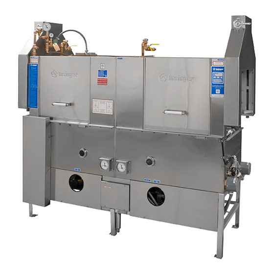
- Page 9 FUNCTIONAL DESCRIPTION The GalleyMaster Dishwasher consists of a wash sec- tion and a rinse section, each with a solution tank, upper spray chamber, and front access door. Solutions in each tank are heated to the operating temperatures (150° F. wash, 160°rinse) by either submerged steam coils or electric immersion heaters.
- Page 10 DATA CHARACTERISTICS Manufacturer: Insinger Machine Company, Philadelphia, PA Type: Insinger GalleyMaster Dishwasher with rack capacity, hand of feed, tank heat, booster, and unloader options. Characteristics: Type: Double tank, rack conveyor dishwasher. Capacity: (based on 20" by 20" racks, manually loaded).
- Page 11 15 months from the date of shipment from Insinger or 1 year (12 months) from the date of installation, that said Insinger product shall be free from defects in material and workman- ship.
- Page 12 (as set out in the instruction booklet). Insinger is not responsible nor liable for any condi- tions of erosion or corrosion caused by corrosive detergents, acids, lye or other chemicals used in the washing, caring and or cleaning process.
- Page 13 This technical manual provides information for the instal- lation, operation, inspection and maintenance of the Gal- leyMaster series of dishwashers manufactured by Insinger Machine Company, Philadelphia, PA. EQUIPMENT DESCRIPTION The GalleyMaster dishwasher is a double tank, rack con- veyor dishwasher used for the washing of plates, glass- ware, and small utensils in 20"...
- Page 14 INTRODUCTION The GalleyMaster Dishwasher is a heavy duty machine designed for daily use in a naval shipboard environment. CONTROLS AND INDICATORS (ELECTRICALLY HEATED MACHINES) ITEM CONTROL Control power switch Control power light Start switch Stop switch Wash tank heat indicator...
-
Page 15: Technical Information
CONTROLS AND INDICATORS (STEAM HEATED MACHINES) ITEM # CONTROL Control power switch. Control power light. Start switch. Stop switch. Wash tank heat indicator. Rinse tank heat indicator. Final rinse heat indicator. Check conveyor indicator. 5 amp circuit breaker. Water and steam ball valves. Damper blade position control. -
Page 16: Start-Up Instructions
START-UP PROCEDURE 1. Before starting the machine, inspect the inside of each tank and make sure that: a. The drain overflow tube is in place. b. The suction strainer is in place over the pump in- take. c. The scrap screens are clean and in place. d. -
Page 17: Cleaning Instructions
CONVEYOR OVERLOAD PROTECTION The conveyor chains move in a smooth continuous mo- tion. Driving power is transmitted from a gearmotor, through a timing belt and sprocket assembly, to the con- veyor drive shaft. Conveyor jams or overloads will cause the drive belt tension to increase, activating an electrical switch which will stop the pumps and conveyor drive motor. - Page 18 WARNING: Float switches, probes and heating elements must be cleaned daily. Accumulations of grease, minerals or debris will cause faulty operation of detergent monitoring and heating systems. Use Scotch-Brite or equivalent cleaning pads on heavy dirt. Use a small wire or pin to clean mineral accumulations from the final hot rinse nozzles.
-
Page 19: Maintenance & Repair Procedures
SCHEDULED MAINTENANCE The GalleyMaster Dishwasher is a rugged and simple machine. The scheduled maintenance described in this chapter is mostly a periodic set of inspections and cleaning. WEEKLY REQUIREMENTS FOR INSPECTION AND MAINTENANCE Inspect for external leakage. Inspect the outside of the machine, including all piping, piping components, rinse water booster, and the tank side and bottom seams for leakage. -
Page 20: Maintenance & Repair Procedures
The tables are separated into operator and maintenance actions. WARNING: Prior to any work on the dishwasher involving service of electri- cal, steam, or water systems, the dish- washer and booster must be de- energized by turning the electrical sup- ply power "Off"... - Page 21 þ NOTE: This section covers actions that can be performed by the operator, without the use of tools. OPERATOR'S TROUBLESHOOTING GUIDE SYMPTOM OF TROUBLE 1. Machine will not operate. 2. Tank will not hold water. 3. Tank fills beyond overflow level. 4.
- Page 22 þ NOTE: This section covers actions that can be performed by qualified maintenance personnel. MAINTENANCE TROUBLESHOOTING GUIDE SYMPTOM OF TROUBLE 1. Machine will not operate. a. No power. b. Blown fuse/breaker. c. Power shut off at disconnect switch. d. Motor overload protection tripping. e.
- Page 23 þ NOTE: This section covers actions that can be performed by qualified maintenance personnel. MAINTENANCE TROUBLESHOOTING GUIDE SYMPTOM OF TROUBLE 8. Water hammer. 9. Machine vibrates (See also water hammer, #8.) 10. Tank and/or booster will not hold specified temperature. 11.
- Page 24 20 psig. Removal and replacement of electric tank heater. See Figure 6-2. Turn off dishwasher power at the main disconnect switch. Drain the appropriate tank. Remove the external heater cover and disconnect the three power wires. Save the paper insulating strip.
- Page 25 Wash and rinse thermometers. See Figure 6-3. 1. Remove the thermometer guard from the outside of the tank. 2. Using a wrench on the hex of the thermometer (behind the dial), unscrew the thermometer from the thermometer well. Do not unscrew by turning the dial case.
- Page 26 Inspection and repair of solenoid actuated valves. Solenoid valves are used on the machine for controlling steam to the booster heater and wash and rinse tank coils (steam heated machines) and the flow of final hot rinse water. If the valve in question will not close, or will not open, inspect the valve.
- Page 27 Fill the tank and check for leaks. Removal and replacement of liquid level float switch. Turn off dishwasher power at the main disconnect switch. Drain the appropriate tank. Disconnect the two switch electric wires. Remove the hex nut and remove the switch from the inside of the tank.
-
Page 28: Spare Parts List
No listing has been provided for parts of permanently assembled items, or for those items which are not suited to field replacement. All parts are available from the Insinger Machine Company, Philadelphia, Pennsylvania 19135. RECOMMENDED GALLEYMASTER SERIES SPARE PARTS LIST... - Page 29 RECOMMENDED GALLEYMASTER SERIES SPARE PARTS LIST Item Part Number 975-56R D2272 D2715A-LS D2715A-RS D2955 975-181 D2-104 975-58 D2935 975-42 DE5-37 D2958 9014-011 9014-012 975-180 954-50A 954-50B 954-50C 975-180-OF D2-557 954-9 D2-549 D-305A D2-550 975-10 975-11 SK-1433 D2930 D2930-RK D2-580 GalleyMaster DOC Revision 2006 NIIN Description 01-445-4688...
- Page 30 RECOMMENDED GALLEYMASTER SERIES SPARE PARTS LIST Item Part Number Additional electrical parts Steam heated machines DE9-167 DE2-52 DE2-91 DE1-109 DE2-38 DE9-251 DE7-31 DE9-252 DE9-92 DE5-4 DE5-60 Additional parts Steam heated machines D2102 D2490-R3 D2490-R3-RK D2301 D2507 GalleyMaster DOC Revision 2006 NIIN Description 01-319-5987...
- Page 31 RECOMMENDED GALLEYMASTER SERIES SPARE PARTS LIST Item Part Number Additional electrical parts Electric heated machines DE9-167 DE2-52 DE2-91 DE1-109 DE2-38 DE9-251 DE7-31 DE9-252 DE13-LE73 DE9-92 DE5-4 DE5-60 DE5-61 Additional electrical parts Power Unloader 1189-59 DE5-63 GalleyMaster DOC Revision 2006 NIIN Description 01-319-5987 Fuse, FNQ-R-1...
-
Page 32: Installation Instructions
Reinstall the loader by reversing above process. Separation of machine. Remove the hot water piping between the booster heater and the dishwasher by "breaking" the two unions on this line. Disconnect and tag the electrical wires and conduit between the booster and the machine. - Page 33 Install the optional power unloader. 1. Position the unloader at the exit of the dishwasher. Place the flange of the unloader table over the lip of the dishwasher rinse tank. Install and tighten the screws and nuts between the unloader and dishwasher housing.
- Page 34 A fresh water feed tube may be connected from the dishwasher wash tank fill piping to the water inlet of the detergent controller. See figure 8-15 for an example.
- Page 35 Check-Out of the Installation Perform the Start-up Procedure. WARNING: At startup, and after any draining of the electric booster, turn off the 440 volt power to the booster during the initial operation of the final hot fresh rinse. This will allow the booster reservoir to fill and trapped air to be purged without overheating of booster heating elements.
-
Page 36: Electrical Schematics & Replacement Parts
PART 7 ELECTRICAL SCHEMATICS & REPLACEMENT PARTS GalleyMaster DOC Revision 2006 www.insingermachine.com 800-344-4802... - Page 37 PART 7 ELECTRICAL SCHEMATICS & REPLACEMENT PARTS GalleyMaster DOC Revision 2006 www.insingermachine.com 800-344-4802...
- Page 38 PART 7 ELECTRICAL SCHEMATICS & REPLACEMENT PARTS GalleyMaster DOC Revision 2006 www.insingermachine.com 800-344-4802...
- Page 39 PART 7 ELECTRICAL SCHEMATICS & REPLACEMENT PARTS GalleyMaster DOC Revision 2006 www.insingermachine.com 800-344-4802...
- Page 40 PART 7 ELECTRICAL SCHEMATICS & REPLACEMENT PARTS GalleyMaster DOC Revision 2006 www.insingermachine.com 800-344-4802...
- Page 41 PART 7 ELECTRICAL SCHEMATICS & REPLACEMENT PARTS GalleyMaster DOC Revision 2006 www.insingermachine.com 800-344-4802...
- Page 42 PART 7 ELECTRICAL SCHEMATICS & REPLACEMENT PARTS GalleyMaster DOC Revision 2006 www.insingermachine.com 800-344-4802...
- Page 43 PART 7 ELECTRICAL SCHEMATICS & REPLACEMENT PARTS GalleyMaster DOC Revision 2006 www.insingermachine.com 800-344-4802...
- Page 44 PART 7 ELECTRICAL SCHEMATICS & REPLACEMENT PARTS GalleyMaster DOC Revision 2006 www.insingermachine.com 800-344-4802...
- Page 45 PART 7 ELECTRICAL SCHEMATICS & REPLACEMENT PARTS GalleyMaster DOC Revision 2006 www.insingermachine.com 800-344-4802...
- Page 46 PART 7 ELECTRICAL SCHEMATICS & REPLACEMENT PARTS GalleyMaster DOC Revision 2006 www.insingermachine.com 800-344-4802...
- Page 47 PART 7 ELECTRICAL SCHEMATICS & REPLACEMENT PARTS GalleyMaster DOC Revision 2006 www.insingermachine.com 800-344-4802...
- Page 48 PART 7 ELECTRICAL SCHEMATICS & REPLACEMENT PARTS GalleyMaster DOC Revision 2006 www.insingermachine.com 800-344-4802...
- Page 49 PART 7 ELECTRICAL SCHEMATICS & REPLACEMENT PARTS GalleyMaster DOC Revision 2006 www.insingermachine.com 800-344-4802...
- Page 50 PART 8 REPLACEMENT PARTS GalleyMaster DOC Revision 2006 www.insingermachine.com 800-344-4802...
- Page 51 PART 8 REPLACEMENT PARTS GalleyMaster DOC Revision 2006 www.insingermachine.com 800-344-4802...
- Page 52 PART 8 REPLACEMENT PARTS GalleyMaster DOC Revision 2006 www.insingermachine.com 800-344-4802...
- Page 53 PART 8 REPLACEMENT PARTS GalleyMaster DOC Revision 2006 www.insingermachine.com 800-344-4802...
- Page 54 PART 8 REPLACEMENT PARTS GalleyMaster DOC Revision 2006 www.insingermachine.com 800-344-4802...
- Page 55 PART 8 REPLACEMENT PARTS GalleyMaster DOC Revision 2006 www.insingermachine.com 800-344-4802...
- Page 56 PART 8 REPLACEMENT PARTS GalleyMaster DOC Revision 2006 www.insingermachine.com 800-344-4802...
- Page 57 PART 8 REPLACEMENT PARTS GalleyMaster DOC Revision 2006 www.insingermachine.com 800-344-4802...
- Page 58 PART 8 REPLACEMENT PARTS GalleyMaster DOC Revision 2006 www.insingermachine.com 800-344-4802...
- Page 59 PART 8 REPLACEMENT PARTS GalleyMaster DOC Revision 2006 www.insingermachine.com 800-344-4802...
- Page 60 PART 8 REPLACEMENT PARTS GalleyMaster DOC Revision 2006 www.insingermachine.com 800-344-4802...
- Page 61 PART 8 REPLACEMENT PARTS GalleyMaster DOC Revision 2006 www.insingermachine.com 800-344-4802...
- Page 62 PART 8 REPLACEMENT PARTS GalleyMaster DOC Revision 2006 www.insingermachine.com 800-344-4802...
- Page 63 PART 8 REPLACEMENT PARTS GalleyMaster DOC Revision 2006 www.insingermachine.com 800-344-4802...
- Page 64 PART 8 REPLACEMENT PARTS GalleyMaster DOC Revision 2006 www.insingermachine.com 800-344-4802...
- Page 65 PART 8 REPLACEMENT PARTS GalleyMaster DOC Revision 2006 www.insingermachine.com 800-344-4802...
- Page 66 PART 8 REPLACEMENT PARTS GalleyMaster DOC Revision 2006 www.insingermachine.com 800-344-4802...
- Page 67 PART 8 REPLACEMENT PARTS GalleyMaster DOC Revision 2006 www.insingermachine.com 800-344-4802...
- Page 68 PART 8 REPLACEMENT PARTS GalleyMaster DOC Revision 2006 www.insingermachine.com 800-344-4802...
- Page 69 PART 8 REPLACEMENT PARTS GalleyMaster DOC Revision 2006 www.insingermachine.com 800-344-4802...
- Page 70 PART 8 REPLACEMENT PARTS GalleyMaster DOC Revision 2006 www.insingermachine.com 800-344-4802...
- Page 71 PART 8 REPLACEMENT PARTS GalleyMaster DOC Revision 2006 www.insingermachine.com 800-344-4802...
- Page 72 PART 8 REPLACEMENT PARTS GalleyMaster DOC Revision 2006 www.insingermachine.com 800-344-4802...
- Page 73 PART 8 REPLACEMENT PARTS GalleyMaster DOC Revision 2006 www.insingermachine.com 800-344-4802...
- Page 74 PART 8 REPLACEMENT PARTS GalleyMaster DOC Revision 2006 www.insingermachine.com 800-344-4802...
- Page 75 PART 8 REPLACEMENT PARTS GalleyMaster DOC Revision 2006 www.insingermachine.com 800-344-4802...
- Page 76 PART 8 REPLACEMENT PARTS GalleyMaster DOC Revision 2006 www.insingermachine.com 800-344-4802...
- Page 77 PART 8 REPLACEMENT PARTS GalleyMaster DOC Revision 2006 www.insingermachine.com 800-344-4802...
- Page 78 PART 8 REPLACEMENT PARTS GalleyMaster DOC Revision 2006 www.insingermachine.com 800-344-4802...
- Page 79 PART 8 REPLACEMENT PARTS GalleyMaster DOC Revision 2006 www.insingermachine.com 800-344-4802...
- Page 80 PART 8 REPLACEMENT PARTS www.insingermachine.com 800-344-4802 GalleyMaster DOC Revision 2006...
- Page 81 6245 State Road Philadelphia, PA 19135-2996 800.344.4802 215.624.4800 Fax 215.624.6966 www.insingermachine.com GalleyMaster DOC Revision 2006 www.insingermachine.com 800-344-4802...
Need help?
Do you have a question about the GalleyMaster 135-LH-E and is the answer not in the manual?
Questions and answers