Advertisement
Quick Links
Download this manual
See also:
Technical Manual
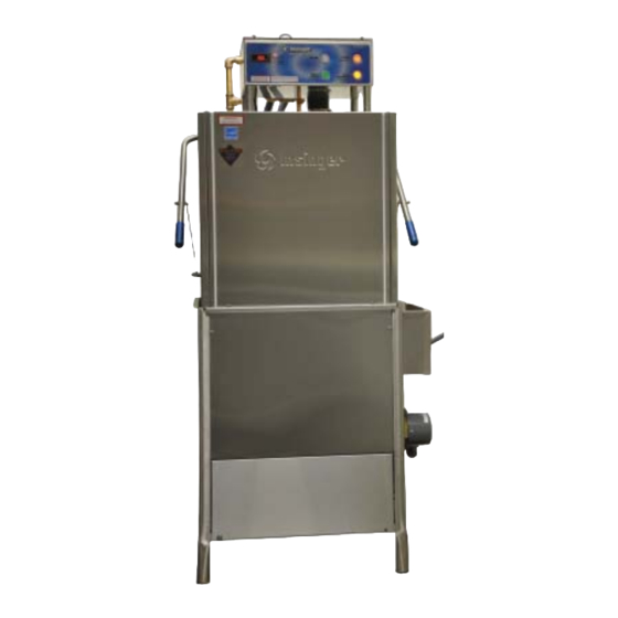
TECHNICAL MANUAL
Door Type Dishwashing Machine
Commander 18-6
Commander 18-6C
Commander 18-6H
Commander 18-6HC
Installation, Operation and Maintenance Instructions
Philadelphia, PA 19135-2996
Insinger Machine Company
6245 State Road
800-344-4802
Fax 215-624-6966
www.insingermachine.com
®
Advertisement

Related Manuals for Insinger Commander 18-6


Summary of Contents for Insinger Commander 18-6
- Page 1 ® TECHNICAL MANUAL Door Type Dishwashing Machine Commander 18-6 Commander 18-6C Commander 18-6H Commander 18-6HC Installation, Operation and Maintenance Instructions Insinger Machine Company 6245 State Road Philadelphia, PA 19135-2996 800-344-4802 Fax 215-624-6966 www.insingermachine.com...
- Page 2 When referring to this equipment please have this information available. 15-19 Part 3 Operating Instructions Each piece of equipment at Insinger is carefully • Operation and Cleaning Instructions tested before shipment for proper operation. If the • Maintenance and Repair Procedures need for service should arise please contact your •...
- Page 3 CSI - 11400 _____________ Item __________________ Approval _______________ Quantity _______________ Date ___________________ COMMANDER 18-6 Automatic Single Tank Door Type Dishwasher DESIGN Automatic door type, single tank dishwasher with timed wash and rinse cycle 0.8 Gallons/rack Capacity is 60- 20” x 20” racks per hour or 1500 dishes per hour...
- Page 4 ® PART 1 TECHNICAL INFORMATION COMMANDER 18-6 Automatic Single Tank Door Type Dishwasher Note: For all rough in connections see installation and layout detail drawing. SPECIFICATIONS Capacity Per Hour 60 racks 1500 dishes CONSTRUCTION- Hood and tank constructed of 16 gauge type 304 S/S.
- Page 5 ® PART 1 TECHNICAL INFORMATION Project ________________ CSI - 11400 _____________ Item __________________ Approval _______________ Quantity _______________ Date ___________________ COMMANDER 18-6H Automatic Extra High Single Tank Door Type Dishwasher DESIGN Automatic door type, single tank dishwasher with timed wash and rinse cycle 0.8 Gallons/rack Capacity is 60- 20”...
- Page 6 ® PART 1 TECHNICAL INFORMATION COMMANDER 18-6H Automatic Extra High Single Tank Door Type Dishwasher Note: For all rough in connections see installation and layout detail drawing. SPECIFICATIONS Capacity Per Hour 60 racks 1500 dishes CONSTRUCTION- Hood and tank constructed of 16 gauge type 304 S/S. 75-150 meals Hood unit of all welded seamless construction.
- Page 7 Defi nitions technicians. Replacement parts may be ordered directly from our factory or from your local Insinger Throughout this guide you will fi nd the following Authorized Service Agency. You can speak to the terms: WARNING, CAUTION, &...
- Page 8 ® PART 1 TECHNICAL INFORMATION Door Type Dishwashing Machine Safety Summary The following are general safety precautions that are not related to any specifi c procedures. These are recommended precautions that personnel must understand and apply during many phases of operation and maintenance.
- Page 9 15 months from the date is not responsible nor liable for any conditions of shipment from Insinger or 1 year (12 months) of erosion or corrosion caused by corrosive from the date of installation or start-up that said...
- Page 10 fi re, fl ood, or improper maintenance said Insinger product shall be free from defects in or service, or failure to perform normal and routine material and workmanship.
-
Page 11: Installation Instructions
® PART 2 INSTALLATION INSTRUCTIONS INSTALLATION INSTRUCTIONS Commander 18-6 Series & CS Series Placement A single-point electrical connection is provided for the pumps, control circuit, and wash tank heater. Carefully uncrate machine. Take caution not to damage If an electric booster is provided, connect power components which may be mounted on the top or directly to the booster. - Page 12 By following the All lines must be fl ushed prior to use to remove debris. operation procedure and general cleaning procedures your Insinger dishwasher will give you years of trouble free service. CAUTION: Do not reduce the size of lines as specifi ed in installa- tion drawings.
- Page 13 ® PART 2 INSTALLATION INSTRUCTIONS DoorTypeTM2009 www.insingermachine.com 800-344-4802...
- Page 14 ® PART 2 INSTALLATION INSTRUCTIONS DoorTypeTM2009 www.insingermachine.com 800-344-4802...
- Page 15 ® PART 2 INSTALLATION INSTRUCTIONS DoorTypeTM2009 www.insingermachine.com 800-344-4802...
- Page 16 ® PART 2 INSTALLATION INSTRUCTIONS DoorTypeTM2009 www.insingermachine.com 800-344-4802...
-
Page 17: Operation Instructions
An inter- By following these operating procedures your lock is provided to stop the wash/rinse cycle Insinger dishwasher will give you years of trouble free if the doors are opened but hot water may service. - Page 18 ® PART 3 OPERATION & CLEANING INSTRUCTIONS CLEANING PROCEDURES (continued) PRESSURE ADJUSTMENT Pressure in the fi nal rinse must be maintained at 20 Clean suction strainers of build-up. ± 2 psi. Adjustment of the pressure is made with the adjusting screw on the pressure reducing valve. NOTE: Improper cleaning of the suction strainers will cause the pumps to cavitate.
- Page 19 ® PART 3 OPERATION & CLEANING INSTRUCTIONS Inspect for dirt, wear or lime build-up. Clean or The following is a basic guide for the repair and replace as required. replacement of common dishwasher parts. Refer to the Basic Services Guide for troubleshooting tips. Reassemble in reverse of disassembly.
- Page 20 ® PART 3 OPERATION & CLEANING INSTRUCTIONS Pump Disassembly (Continued) Remove the pump motor and impeller by removing the 4 hex bolts attaching them to the pump housing. Repair or replace the pump parts as required. Reassemble in reverse of disassembly. Immersion Heater Replacement See dwg.
-
Page 21: Motor Overloads
OPERATION & CLEANING INSTRUCTIONS Motor Overloads Level System All motors used on Insinger Machines are provided The level control system consists of one overfi ll timer with motor overloads. Motor overloads are adjusted (P/N DE7-35) and one level fl oat (P/N DEF-60) per when the machines are factory tested. - Page 22 PART 4 ELECTRICAL SCHEMATICS ® & REPLACEMENT PARTS DoorTypeTM2009 www.insingermachine.com 800-344-4802...
- Page 23 PART 4 ELECTRICAL SCHEMATICS ® & REPLACEMENT PARTS DoorTypeTM2009 www.insingermachine.com 800-344-4802...
- Page 24 PART 4 ELECTRICAL SCHEMATICS ® & REPLACEMENT PARTS DoorTypeTM2009 www.insingermachine.com 800-344-4802...
- Page 25 PART 4 ELECTRICAL SCHEMATICS ® & REPLACEMENT PARTS DoorTypeTM2009 www.insingermachine.com 800-344-4802...
- Page 26 ® PART 4 ELECTRICAL SCHEMATICS & REPLACEMENT PARTS DoorTypeTM2009 www.insingermachine.com 800-344-4802...
- Page 27 PART 4 ELECTRICAL SCHEMATICS ® & REPLACEMENT PARTS DoorTypeTM2009 www.insingermachine.com 800-344-4802...
- Page 28 PART 4 ELECTRICAL SCHEMATICS ® & REPLACEMENT PARTS DoorTypeTM2009 www.insingermachine.com 800-344-4802...
- Page 29 PART 4 ELECTRICAL SCHEMATICS ® & REPLACEMENT PARTS DoorTypeTM2009 www.insingermachine.com 800-344-4802...
- Page 30 PART 4 ELECTRICAL SCHEMATICS ® & REPLACEMENT PARTS DoorTypeTM2009 www.insingermachine.com 800-344-4802...
- Page 31 PART 4 ELECTRICAL SCHEMATICS ® & REPLACEMENT PARTS DoorTypeTM2009 www.insingermachine.com 800-344-4802...
- Page 32 PART 4 ELECTRICAL SCHEMATICS ® & REPLACEMENT PARTS DoorTypeTM2009 www.insingermachine.com 800-344-4802...
- Page 33 PART 4 ELECTRICAL SCHEMATICS ® & REPLACEMENT PARTS DoorTypeTM2009 www.insingermachine.com 800-344-4802...
- Page 34 PART 4 ELECTRICAL SCHEMATICS ® & REPLACEMENT PARTS DoorTypeTM2009 www.insingermachine.com 800-344-4802...
- Page 35 PART 4 ELECTRICAL SCHEMATICS ® & REPLACEMENT PARTS DoorTypeTM2009 www.insingermachine.com 800-344-4802...
- Page 36 PART 4 ELECTRICAL SCHEMATICS ® & REPLACEMENT PARTS DoorTypeTM2009 www.insingermachine.com 800-344-4802...
- Page 37 PART 4 ELECTRICAL SCHEMATICS ® & REPLACEMENT PARTS DoorTypeTM2009 www.insingermachine.com 800-344-4802...
- Page 38 PART 4 ELECTRICAL SCHEMATICS ® & REPLACEMENT PARTS DoorTypeTM2009 www.insingermachine.com 800-344-4802...
- Page 39 PART 4 ELECTRICAL SCHEMATICS ® & REPLACEMENT PARTS DoorTypeTM2009 www.insingermachine.com 800-344-4802...
- Page 40 PART 4 ELECTRICAL SCHEMATICS ® & REPLACEMENT PARTS DoorTypeTM2009 www.insingermachine.com 800-344-4802...
- Page 41 PART 4 ELECTRICAL SCHEMATICS ® & REPLACEMENT PARTS DoorTypeTM2009 www.insingermachine.com 800-344-4802...
- Page 42 PART 4 ELECTRICAL SCHEMATICS ® & REPLACEMENT PARTS DoorTypeTM2009 www.insingermachine.com 800-344-4802...
- Page 43 PART 4 ELECTRICAL SCHEMATICS ® & REPLACEMENT PARTS DoorTypeTM2009 www.insingermachine.com 800-344-4802...
- Page 44 PART 4 ELECTRICAL SCHEMATICS ® & REPLACEMENT PARTS DoorTypeTM2009 www.insingermachine.com 800-344-4802...
- Page 45 PART 4 ELECTRICAL SCHEMATICS ® & REPLACEMENT PARTS DoorTypeTM2009 www.insingermachine.com 800-344-4802...
- Page 46 PART 4 ELECTRICAL SCHEMATICS ® & REPLACEMENT PARTS DoorTypeTM2009 www.insingermachine.com 800-344-4802...
- Page 47 PART 4 ELECTRICAL SCHEMATICS ® & REPLACEMENT PARTS CONVERT 18-6 STRAIGHT TO CORNER DOOR CONVERSION All 3 doors open on a straight machine; only the front & right hand doors are used on a comer. The front is defi ned as facing the center door with the springs on the back.
- Page 48 ® Insinger Machine Company 6245 State Road Philadelphia, PA 19135-2996 800-344-4802 Fax 215-624-6966...
Need help?
Do you have a question about the Commander 18-6 and is the answer not in the manual?
Questions and answers
I have an Insinger Commander 18-6 sn 168403. I delimed the unit last night and this morning the water is brown in the unit not in any sink. Any troubleshooting hints? Ran several times.