
Related Manuals for Xantrex XPLORE 120/12


Summary of Contents for Xantrex XPLORE 120/12
- Page 1 Owner’s Guide Model XPLORE 120/12 Battery Charger XPLORE 120/12 Battery Charger 819-0120-12...
- Page 2 ACCURACY OF THE TRANSLATION, THE ACCURACY CANNOT BE GUARANTEED. APPROVED CONTENT IS CONTAINED WITH THE ENGLISH LANGUAGE VERSION WHICH IS POSTED AT http://www.xantrex.com. NOTE: Visit http://www.xantrex.com, select PRODUCTS, select a Product category, select a Product, select DOWNLOADS, and choose a document from the list that may provide a translation of the English guide, if available.
- Page 3 Information About Your System As soon as you open your product, record the following information and be sure to keep your proof of purchase. Serial Number ____________________________ Product Number ____________________________ Purchased From ____________________________ Purchase Date ____________________________ To view, download, or print the latest revision, visit the website shown under Contact Information. 975-1038-01-01...
- Page 4 Selecting and using Personal Protective Equipment (PPE). Product Number Related Information Personal Protective Equipment Society of Automotive Engineers You can find more information about Xantrex products and V, VAC, Voltage, Volts AC, Volts DC services at http://www.xantrex.com. Wattage XPLORE 120/12 Battery Charger Owner's Guide...
-
Page 5: Important Safety Instructions
IMPORTANT SAFETY INSTRUCTIONS SAVE THESE INSTRUCTIONS reassembly may result in a risk of electric shock or fire. ALL SERVICING should be performed by qualified service 1. SAVE THESE INSTRUCTIONS—This manual contains personnel. important safety and operating instructions for the battery 8. - Page 6 The charging terminals are not intended f. Determine voltage of battery by referring to car owner’s to supply power to an extra-low-voltage electrical system manual and make sure it matches output rating of battery XPLORE 120/12 Battery Charger Owner's Guide...
- Page 7 charger. Charge battery initially at lowest charge rate, if a. Position ac and dc cords to reduce risk of damage by possible. hood, door, or moving engine part. 12. CHARGER LOCATION b. Stay clear of fan blades, belts, pulleys, and other parts that can cause injury to persons.
- Page 8 WARNING indicates a hazardous situation which, if not avoided, could result equipment-grounding terminal or lead on battery in death or serious injury. charger. Connections to battery charger should comply with all local codes and ordinances. CAUTION viii XPLORE 120/12 Battery Charger Owner's Guide...
-
Page 9: Emi Information To The User
Regulatory EMI Information to the User CAUTION indicates a hazardous situation which, if not avoided, could result in minor or moderate injury. This equipment has been tested and found to comply with the limits for a Class B digital device, pursuant to part 15 of the FCC / NOTICE CAN ICES-003 Rules. -
Page 10: End Of Life Disposal
Many of the electrical components used in the XPLORE 120/12 Battery Charger are made of recyclable material like steel, copper, aluminum, and other alloys. These materials can be auctioned off to traditional scrap metal recycling companies who resell reusable scraps. -
Page 11: Table Of Contents
CONTENTS Important Safety Instructions Installing the XPLORE 120/12 Battery Charger Regulatory Installation Sequence Battery Operation EMI Information to the User End of Life Disposal Input Voltage Operating and Derating Introduction Dual Chemistry Charging XPLORE 120/12 Battery Charger Three-Stage Charging Product Features... - Page 12 Troubleshooting Maintaining the Charger Troubleshooting Specifications Physical Specifications Environmental Specifications AC Input Specifications DC Output Specifications Protection Features Accessory Regulatory Approvals XPLORE 120/12 Battery Charger Owner's Guide...
-
Page 13: Introduction
INTRODUCTION The XPLORE 120/12 Battery Charger is designed with dual chemistry, multiple battery bank charging features suitable for Recreational or Commercial Marine installations. Please read this section to familiarize yourself with the main performance and protection features of the XPLORE Charger. -
Page 14: Xplore 120/12 Battery Charger
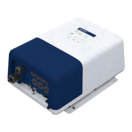
XPLORE 120/12 Battery Charger XPLORE 120/12 Battery Charger Product Features The XPLORE Charger ships with the following items: The XPLORE 120/12 Battery Charger provides the following standard features: A. one XPLORE Charger unit up to six battery bank outputs: B. one Xantrex BLE Module (PN: 808-0889) package - first group (house) has two banks totaling 120 A... - Page 15 158 °F (70 °C) or higher charging voltage compensation based on the temperature of the battery the BTS is connected to Contact Xantrex or your Xantrex dealer for these optional accessories. 975-1038-01-01...
- Page 16 This page is intentionally left blank. [2]...
-
Page 17: Features
FEATURES This section identifies the default settings and the hardware features of the XPLORE 120/12 Battery Charger. This section includes: Front Panel Terminals and Ports Onboard Status LED Panel Accessories 975-1038-01-01... -
Page 18: Front Panel
Use a torque screwdriver to tighten both the captive nut panel screws to 5 in-lb (0.56 N-m) torque to ensure a required tool access to the wiring compartment. Failure to follow these instructions can result in death, serious injury, or equipment damage. XPLORE 120/12 Battery Charger Owner's Guide... -
Page 19: Terminals And Ports
USB port - for connecting a USB stick used in copying settings and updating firmware c Not to be used to power or charge USB devices. RJ12 expansion port - for connecting to the Xantrex BLE J K L M N Module (PN: 808-0889) -
Page 20: Onboard Status Led Panel
- displays the status of BAT3- disabled. BAT6 (group 2). Individual solid green indicates each battery is connected and detected. Off means a battery is not present. XPLORE 120/12 Battery Charger Owner's Guide... -
Page 21: Accessories
Accessories Accessories This section lists all available accessories for the XPLORE 120/12 Battery Charger. To order, contact Xantrex or your authorized dealer. Battery Temp Sensor (BTS) with 25-ft cable (PN: 808-0232-01) 975-1038-01-01... - Page 22 This page is intentionally left blank. [2]...
-
Page 23: Basic Installation
BASIC INSTALLATION Please read this section for safety information and installation instructions regarding your XPLORE Charger. This section includes: Preparing For Installation Tools and Materials Location Wiring Requirements Configuring Charge Current for Battery Size Installing the XPLORE 120/12 Battery Charger 975-1038-01-01... -
Page 24: Preparing For Installation
AC source connection. It also shows the AC and DC wiring and protection devices required for a safe installation. Means of over-current protection and disconnection must be incorporated into the fixed wiring, in accordance with the electrical code that governs each installation. XPLORE 120/12 Battery Charger Owner's Guide... - Page 25 Preparing For Installation Figure 4 Battery Connections AC source protected by correct size and Connection to main DC neg(-) ground bus type of branch rated single-pole circuit breaker AC terminals [G, L, N) protected by fuses Battery cable (neg(-)) Battery positive (+) terminals for BAT3 Battery cable (pos(+)) through BAT6 (Group 2) Battery positive (+) terminals from left to...
-
Page 26: Tools And Materials
3% voltage drop on battery cables under a 2-way cable gland electrical junction box full load. This will maximize the performance of the four pieces mounting screws, #10 corrosion resistant charger. (Length dependent on mounting surface). XPLORE 120/12 Battery Charger Owner's Guide... - Page 27 Preparing For Installation NOTES: Condition Requirement When planning to install the XPLORE Charger, be sure that you Ventilated There must be at least 4 in. (10 cm) of clearance on consider the location and orientation carefully. The XPLORE the top and bottom ends (A) of the XPLORE Charger has an IP rating of IP32 (vertical only as shown in Figure Charger for air flow and at least 6 in. (15 cm) of 5 ).
- Page 28 Vertical Wall Mount (Wiring panel facing down) - this meets IP32 requirements and is drip-proof. Deck Mount - this orientation is not recommended for IP- rated orientation. Horizontal Wall Mount - this orientation is not recommended for IP-rated orientation. XPLORE 120/12 Battery Charger Owner's Guide...
-
Page 29: Wiring Requirements
Preparing For Installation DC (Battery) Wiring Wiring Requirements The following tables show some typical wire sizes for various cable length runs, based on 3% voltage drop on DC cables, 167 °F DANGER (75 °C) rated wire with wiring being inside the engine compartment –... - Page 30 (or G, L, N) in an outer jacket, rated a minimum of 75 °C, and sized 60 A based on the AC input current to the charger (see AC Input Specifications on page 53) and on the value of overcurrent protection provided. XPLORE 120/12 Battery Charger Owner's Guide...
- Page 31 Preparing For Installation Other examples of AC wiring requirements: For example: For RV applications, the United States National Electrical Code In US NEC, you may use a 14 AWG wire with a 15 A (NEC) allows solid wire in multi-conductor cable, however, breaker for up to 12 A continuous current (or 12 AWG for a stranded wire is also acceptable which will withstand vibration 20 A breaker for up to 16 A continuous current)
-
Page 32: Configuring Charge Current For Battery Size
NOTE: If the battery manufacturer has specified the maximum charge current, please follow their recommendation. Table 3 Recommended Minimum Battery Size Model Battery Bank Size (Ah) Group 1 Group 2 XPLORE 120/12 Battery Charger Owner's Guide... -
Page 33: Installing The Xplore 120/12 Battery Charger
Installing the XPLORE 120/12 Battery Charger Installing the XPLORE 120/12 Battery Charger Be sure to read the safety guidelines and pay attention to all cautions and warnings throughout the installation procedure. The installer is responsible for ensuring compliance with the installation codes for your particular application. -
Page 34: Installation Sequence
5. Permanently secure the XPLORE Charger to the wall by fastening the two top anchors as well driving two additional anchors through the two round holes on the flanges. XPLORE 120/12 Battery Charger Owner's Guide... - Page 35 Figure 7 Mounting flanges Step 2: Installing DC Wiring The procedure for installing the DC wiring applies to a single battery, as well as multiple batteries or battery banks. WARNING ACCIDENTAL SHORT OR SPARK HAZARD Leave the DC disconnects or breakers in the Off position or DC fuses removed from their fuse holders until installation is complete.
- Page 36 NOTE: You may find it helpful to label each cable, associating it with the battery bank it is connected to. For example, NEG (–), BAT1, BAT2, and so on. XPLORE 120/12 Battery Charger Owner's Guide...
- Page 37 6. Connect the negative cable from the negative terminal on NOTICE the battery to the negative DC terminal on the XPLORE Charger. See Terminal stacking below for proper REVERSE POLARITY DAMAGE connection. 7. Tighten the flare nut to 20 lb-in.(2.3 N-m) torque and test by Before proceeding to the next step, carefully check the wiring tugging that the wire is secure.
- Page 38 10. If there are additional battery banks to connect, repeat the ambient temperature) to the charger location. preceding steps for each additional battery bank. See 15. Proceed to Step 3: Installing AC Wiring. Polarity connections. XPLORE 120/12 Battery Charger Owner's Guide...
- Page 39 4. Carefully remove 3 in. (75 mm ) of the outer jacket from the Step 3: Installing AC Wiring AC supply wiring, being careful not to cut or nick the Before connecting AC wiring, make sure the AC source circuit is insulation on the individual wires (conductors). protected by a breaker switch of the correct size and type, to 5.
- Page 40 Failure to follow these instructions can result in death, serious injury, or equipment damage. 9. Secure cables in place using tie-wraps or cable straps according to electrical codes. 10. Tighten the cable glands, if applicable. XPLORE 120/12 Battery Charger Owner's Guide...
- Page 41 Step 4: Powering Up Figure 13 LEDs when powered Make one last check that all connections are correct and secure. The XPLORE Charger may now be powered up. 1. Close the DC disconnect switch or breaker. Bank 2. Switch the AC power on at the source breaker. It is normal to see a seven to ten second delay while the charger Status powers up.
- Page 42 This page is intentionally left blank. [2]...
-
Page 43: Battery Operation
BATTERY OPERATION Please read this section for safety information and operational Input Voltage Operating and instructions regarding your XPLORE Charger. This section Derating includes: When AC input is within the lower range between 90–108 VAC, Input Voltage Operating and Derating the XPLORE Charger derates to 80% of maximum current. Dual Chemistry Charging However, when AC input increases above 108 VAC up to Three-Stage Charging... -
Page 44: Three-Stage Charging
< 10% lrating Flooded for 1 minute Battery Voltage Vbat < 12.5 V for 15 minutes Charge start BULK FLOAT Time Total ABS timeout FLOAT timeout Start of max 8 hrs max 21 days charging cycle XPLORE 120/12 Battery Charger Owner's Guide... -
Page 45: Two-Stage Charging
Two-Stage Charging Two-Stage Charging Float Only Charging The two-stage charging mode employs the following sequence: The float-only charging mode maintains a maximum charging Bulk and Absorption. It runs similar to the three-stage sequence voltage equal to a preset float voltage. A float stage is applied except that there is no float stage;... -
Page 46: Charging Voltage Setpoints
Attach the BTS to the warmest battery. LiFePO 14.6 13.4 4 applicable If no BTS is connected, the charger defaults to 25 °C. 14.4 13.4 Custom (default, (default, applicable changeable) changeable) XPLORE 120/12 Battery Charger Owner's Guide... -
Page 47: Configuration
This section includes descriptions on how to change charger settings of the XPLORE 120/12 Battery Charger using the Xantrex BLE Module (PN: 808-0889). If you do not connect the BLE Module, you can only configure the battery type for each battery bank using the Onboard Status LED Panel on page 8. -
Page 48: Configuring The Battery Charger
Onboard Status LED Panel on page 8 NOTE: Be sure to connect the Xantrex BLE Module (PN: 808- 0889) and install the Xantrex App on your smart device in order to configure your XPLORE Charger. Use the instructions provided with the XPLORE Charger. -
Page 49: Operation
OPERATION This section includes descriptions of the different modes and settings of the XPLORE 120/12 Battery Charger. This section includes: Transitioning Power States Charging Batteries Equalizing Flooded Batteries Using A Generator As Source Power 975-1038-01-01... -
Page 50: Transitioning Power States
See note 2. Disconnect all DC batteries. below. Failure to follow these instructions will result in death or serious injury. XPLORE 120/12 Battery Charger Owner's Guide... -
Page 51: Charging Batteries
Transitioning Power States To charge your batteries: Charging Batteries 1. If possible, disconnect any heavy loads on the batteries Before you start to charge batteries read the Important Safety being charged, by opening disconnect switches or by Information on page 1 and follow all safety precautions when switching the loads off. -
Page 52: Equalizing Flooded Batteries
In the following conditions the XPLORE Charger will not enter Equalizing Flooded Batteries equalization mode: IMPORTANT: Connect the Xantrex BLE Module (PN: 808-0889) the battery type is set to GEL, AGM, LFP, or CUS in order to use this function. - Page 53 Transitioning Power States Performing An Equalization NOTE: If battery acid contacts skin or clothing, wash immediately with soap and water. If acid enters your eye, immediately flood it with running cold water for at least twenty minutes and get NOTICE medical attention immediately.
- Page 54 To manually exit equalization mode early, repeat Step 3. 7. Check the battery electrolyte level. If necessary, refill with distilled water only and repeat a normal charge cycle. XPLORE 120/12 Battery Charger Owner's Guide...
-
Page 55: Using A Generator As Source Power
This scenario can cause the battery charger to shutdown. Adjusting the Maximum Charging Current setting can help avoid this scenario (using the optional Xantrex App). The XPLORE Charger may be used with modified sine wave generators but its lifetime may be reduced somewhat depending on the severity of any peak voltage overshoots and the severity of waveshape rise times. - Page 56 This page is intentionally left blank. [2]...
-
Page 57: Troubleshooting
TROUBLESHOOTING This section will help you narrow down the source of any problem you encounter. This section includes: Maintaining the Charger Troubleshooting 975-1038-01-01... -
Page 58: Maintaining The Charger
NOTE: The XPLORE 120/12 Battery Charger does not have any Do not operate if the charger contains moisture of any kind. user-serviceable parts. Do not disassemble the XPLORE Charger... - Page 59 For more help not covered in Possible Cause Solution this section, please contact http://www.xantrex.com/power- XPLORE Charger does not Check quality of battery products-support/.
- Page 60 Using the Xantrex App, you may of its useful life and can no longer reduce the output current using accept a charge. the Max Charging Current setting. If battery is too cold, allow batteries to warm up. XPLORE 120/12 Battery Charger Owner's Guide...
- Page 61 Troubleshooting Symptom Symptom The XPLORE Charger appears to be taking too long to charge The XPLORE Charger appears to have quickly charged the battery. Ready indicator LED does not illuminate after 24 hours of battery. Ready indicator LED illuminates sooner than expected. charging.
- Page 62 An active fault is present on Clear the active fault by the bank you are attempting disconnecting the AC power to equalize. source and finding the cause of the fault from Interpreting Alert Indicators on page 1. XPLORE 120/12 Battery Charger Owner's Guide...
- Page 63 This section summarizes the hardware and electrical DISCLAIMER REGARDING STATUS DATA specifications of the XPLORE 120/12 Battery Charger. This STATUS DATA REPORTED BY THE XPLORE 120/12 BATTERY CHARGER ARE APPROXIMATE VALUES INTENDED TO PROVIDE GENERAL AND section includes: NON-EXACT INFORMATION ABOUT THE XPLORE 120/12 BATTERY CHARGER.
-
Page 64: Physical Specifications
6.5” 9.6” 16.3” 10.2” 243mm 413mm 258mm 0.2” 80% current derating above 50 °C (122 °F). Operation may be limited depending on battery chemistry. Consult with the battery manufacturer for specific operational capacities regarding their batteries. XPLORE 120/12 Battery Charger Owner's Guide... -
Page 65: Ac Input Specifications
AC Input Specifications AC Input Specifications DC Output Specifications XPLORE 120/12 Battery XPLORE 120/12 Battery Charger Charger AC input voltage range Battery types Flooded, GEL, AGM, LFP (lithium iron phosphate), or Custom Nominal: 110 | 120 | 230 | 240 VAC Battery bank size 600 Ah Full: 100 – 270 VAC... -
Page 66: Protection Features
< 0.1 VDC drop from 0 Amps to rated protection temperature below –13 °F (–25 °C) is current output at charger output sensed by the battery temperature terminals (adds in series with sensor (BTS). recommended 3% limit for user's battery cable voltage drop). XPLORE 120/12 Battery Charger Owner's Guide... -
Page 67: Accessory
Accessory Regulatory Approvals XPLORE 120/12 Battery XPLORE 120/12 Battery Charger Charger To order, contact Xantrex or your Battery Temp Sensor (BTS) with 25-ft Safety NRTL listed to CSA C22.2 No. 107.2, authorized dealer. cable (PN: 808-0232-01) UL1236 (with marine supplement) UL1564, and ABYC E-11, A-31. - Page 68 +1-800-670-0707 +1-408-987-6030 975-1038-01-01 Rev A Printed in: 30996...
Need help?
Do you have a question about the XPLORE 120/12 and is the answer not in the manual?
Questions and answers