
Subscribe to Our Youtube Channel
Related Manuals for Xantrex XPLORE 120A 12V


Summary of Contents for Xantrex XPLORE 120A 12V
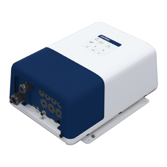
- Page 1 Owner’s Guide Model XPLORE 120A 12V Battery Charger XPLORE 120/12 Battery Charger 819-0120-12...
- Page 2 ACCURACY OF THE TRANSLATION, THE ACCURACY CANNOT BE GUARANTEED. APPROVED CONTENT IS CONTAINED WITH THE ENGLISH LANGUAGE VERSION WHICH IS POSTED AT http://www.xantrex.com. NOTE: Visit http://www.xantrex.com, select PRODUCTS, select a Product category, select a Product, select DOWNLOADS, and choose a document from the list that may provide a translation of the English guide, if available.
- Page 3 Information About Your System As soon as you open your product, record the following information and be sure to keep your proof of purchase. Serial Number ____________________________ Product Number ____________________________ Purchased From ____________________________ Purchase Date ____________________________ To view, download, or print the latest revision, visit the website shown under Contact Information. 975-1038-01-01...
- Page 4 The purpose of this Owner’s Guide is to provide explanations and Amperes procedures for installing, operating, configuring, maintaining, and ABYC American Boat and Yacht Council troubleshooting a XPLORE 120A 12V Battery Charger for AC, V Alternating Current Recreational or Commercial Marine installations. Amp-hours (a unit of battery capacity)
- Page 5 Product rating and safety labels Personal Protective Equipment Residual Current Circuit Breaker with Overcurrent Protection RCBO Read these instructions carefully and look at the equipment to (Type B) become familiar with the device before installing, operating, Society of Automotive Engineers configuring, maintaining, and troubleshooting it.
- Page 6 CAUTION CAUTION indicates a hazardous situation which, if not avoided, could result in minor or moderate injury. NOTICE NOTICE is used to address practices not related to physical injury. Figure 1 Product rating label (sample) NOTE: Actual label may vary. Figure 2 Product safety label (sample) NOTE: Actual label may vary.
-
Page 7: Important Safety Instructions
IMPORTANT SAFETY INSTRUCTIONS SAVE THESE INSTRUCTIONS reassembly may result in a risk of electric shock or fire. ALL SERVICING should be performed by qualified service 1. SAVE THESE INSTRUCTIONS—This manual contains personnel. important safety and operating instructions for the battery 8. - Page 8 10. PERSONAL PRECAUTIONS other than in starter-motor or power storage applications. Do not use battery charger for charging dry-cell or a. Consider having someone close enough by to come to primary batteries that are commonly used with home your aid when you work near a lead-acid battery. appliances.
- Page 9 of battery charger. Charge battery initially at lowest a. Position ac and dc cords to reduce risk of damage by charge rate, if possible. hood, door, or moving engine part. 12. CHARGER LOCATION b. Stay clear of fan blades, belts, pulleys, and other parts that can cause injury to persons.
-
Page 10: Regulatory
Regulatory 15. FOLLOW THESE STEPS WHEN BATTERY IS OUTSIDE Regulatory VESSEL. A SPARK NEAR THE BATTERY MAY CAUSE The XPLORE Charger conforms to the appropriate European, US, BATTERY EXPLOSION. TO REDUCE RISK OF A SPARK NEAR BATTERY: and Canadian standards. For more information see Regulatory Approvals North America and Regulatory Approvals IEC/EN on a. -
Page 11: Emc/Emi Information To The User
End of Life Disposal This equipment has been tested and found to comply with the The XPLORE 120A 12V Battery Charger is designed with limits for a Class B digital device, pursuant to EMC directive and environmental awareness and sustainability in mind. At the end of part 15 of the FCC / CAN ICES-003 Rules. - Page 12 This page is intentionally left blank. [2]...
-
Page 13: Table Of Contents
CONTENTS Important Safety Instructions Installing the XPLORE 120A 12V Battery Charger Regulatory Installation Sequence Battery Operation EMC/EMI Information to the User End of Life Disposal Input Voltage Operating and Derating Introduction Dual Chemistry Charging XPLORE 120A 12V Battery Charger Three-Stage Charging... - Page 14 Troubleshooting Maintaining the Charger Troubleshooting Specifications Physical Specifications Environmental Specifications AC Input Specifications DC Output Specifications Protection Features Accessory Regulatory Approvals North America Regulatory Approvals IEC/EN XPLORE 120/12 Battery Charger Owner's Guide...
-
Page 15: Introduction
INTRODUCTION The XPLORE 120A 12V Battery Charger is designed with dual chemistry, multiple battery bank charging features suitable for Recreational or Commercial Marine installations. Please read this section to familiarize yourself with the main performance and protection features of the XPLORE Charger. -
Page 16: Xplore 120A 12V Battery Charger
XPLORE 120A 12V Battery Charger XPLORE 120A 12V Battery Product Features The XPLORE 120A 12V Battery Charger provides the Charger following standard features: The XPLORE Charger ships with the following items: up to six battery bank outputs: A. one XPLORE Charger unit - first group (house) has two banks totaling 120 A... - Page 17 158 °F (70 °C) or higher charging voltage compensation based on the temperature of the battery the BTS is connected to Contact Xantrex or your Xantrex dealer for these optional accessories. 975-1038-01-01...
- Page 18 This page is intentionally left blank. [2]...
-
Page 19: Features
FEATURES This section identifies the default settings and the hardware features of the XPLORE 120A 12V Battery Charger. This section includes: Front Panel Terminals and Ports Onboard Status LED Panel Accessories 975-1038-01-01... -
Page 20: Front Panel
Front Panel Front Panel Item Description Figure 3 Front Panel Mounting flanges are used to permanently install the product. Onboard status LED panel (see Onboard Status LED Panel on page 8 for more information) for monitoring charging status for the three banks. -
Page 21: Terminals And Ports
USB port - for connecting a USB stick used in copying settings and updating firmware c Not to be used to power or charge USB devices. RJ12 expansion port - for connecting to the Xantrex BLE J K L M N Module (PN: 808-0889) Equipment ground terminal - for connecting to the vessel chassis. -
Page 22: Onboard Status Led Panel
Onboard Status LED Panel Onboard Status LED Panel Item Description This section describes the parts of the onboard status LED panel Status LEDs of the XPLORE Charger. See Reading Onboard Display LEDs on Solid - battery is fully charged (float stage). page 1 for more information. -
Page 23: Accessories
Accessories Accessories This section lists all available accessories for the XPLORE 120A 12V Battery Charger. To order, contact Xantrex or your authorized dealer. Battery Temp Sensor (BTS) with (7.6m) 25-ft cable (PN: 808-0232-01) 975-1038-01-01... - Page 24 This page is intentionally left blank. [2]...
-
Page 25: Basic Installation
Tools and Materials specifications to avoid damaging the battery due to overcharging. Location Failure to follow these instructions can result in equipment Wiring Requirements damage. Configuring Charge Current for Battery Size Installing the XPLORE 120A 12V Battery Charger 975-1038-01-01... -
Page 26: Preparing For Installation
This equipment must only be installed and serviced by compliance with all applicable installation and electrical codes and qualified electrical personnel. regulations. Instructions for installing the XPLORE 120A 12V Never operate energized with the wiring compartment cover Battery Charger are provided here for use by qualified personnel removed. - Page 27 Preparing For Installation NOTE: The XPLORE Charger is designed to be permanently mounted. Figure 6 shows a full installation with six batteries and an AC (mains) source connection. It also shows the AC and DC wiring and protection devices required for a safe installation. Means of over-current protection and disconnection must be incorporated into the fixed wiring, in accordance with the electrical code that governs each installation.
- Page 28 Preparing For Installation Figure 6 Battery Connections AC (mains) source protected by correct size Connection to vessel chassis and type of branch rated circuit breaker*. * single pole breaker for North America * double-pole breaker for Europe AC (mains) source terminals [G/PE, L, N) Battery cable (neg(-)) protected by fuses Battery positive (+) terminals for BAT3...
-
Page 29: Tools And Materials
Preparing For Installation Tools and Materials Location To mount and connect the XPLORE Charger you need the Install the XPLORE Charger in a location that meets the following following tools: requirements: Phillips #2 (3.5mm or equivalent) torque screwdriver for Condition Requirement removing and re-securing the AC and DC wiring compartment cover... - Page 30 Preparing For Installation Condition Requirement DANGER Ventilated ELECTRICAL SHOCK HAZARD In moist environments, there is a likelihood that condensation will be present and may drip on to the charger. Use the appropriate mounting orientations as shown in Figure 7 . Ventilation openings located at the top and bottom of the base mounting plate on the charger must not be obstructed.
- Page 31 Preparing For Installation Figure 7 Mounting Orientations (deck versus wall) IP-rated Vertical Wall Mount (Wiring panel facing down) - this meets IP32 requirements and is drip-proof. Deck Mount - this orientation is not recommended for IP- rated orientation. Horizontal Wall Mount - this orientation is not recommended for IP-rated orientation.
-
Page 32: Wiring Requirements
Preparing For Installation DC (Battery) Wiring Wiring Requirements The following tables show some typical wire sizes for various cable length runs, based on 3% voltage drop on DC cables, 167 °F DANGER (75 °C) rated wire with wiring being inside the engine compartment –... - Page 33 Preparing For Installation Over-current Protection Disconnect AC Wiring Electrical codes require the DC circuit from each battery to the charger to be equipped with a disconnect and an over-current DANGER protection device, usually within 7 inches (17.8 cm) of each battery.
- Page 34 Preparing For Installation Other examples of AC wiring requirements: For example: Conductors and flexible cords shall be stranded copper for the In US NEC, you may use a 14 AWG wire with a 15 A marine environment. breaker for up to 12 A continuous current (or 12 AWG for a 20 A breaker for up to 16 A continuous current) The AC (mains) wiring supplying the XPLORE Charger must be Note that every jurisdiction will have different requirements...
-
Page 35: Configuring Charge Current For Battery Size
Preparing For Installation Configuring Charge Current for Battery Size The XPLORE Charger is designed to work with a minimum battery bank size. Each bank should meet the minimum Ah rating shown in Table 3. These minimum values are based on twice the charger’s rated maximum charging current. -
Page 36: Installing The Xplore 120A 12V Battery Charger
Installing the XPLORE 120A 12V Battery Charger Installing the XPLORE 120A 12V Battery Charger Be sure to read the safety guidelines and pay attention to all cautions and warnings throughout the installation procedure. The installer is responsible for ensuring compliance with the installation codes for your particular application. -
Page 37: Installation Sequence
Step 1: Mounting the Battery Charger Installation Sequence Mount the XPLORE Charger using all four mounting keyholes of To make charger installation quick and easy, perform the the mounting brackets. See Mounting flanges on page 24. installation tasks in the following sequence: Unit mounting orientations shown on page 17 meet IP32 and drip- Step 1: Mounting the Battery Charger proof requirements that are needed to ensure safety in the... - Page 38 4. Hang the XPLORE Charger on the two anchors making Step 2: Connecting the DC Equipment sure the flanges are flush to the wall and the screw heads Ground/Earth are positioned on the narrow side of the key holes. 5. Permanently secure the XPLORE Charger to the wall by fastening the two top anchors as well driving two additional WARNING anchors through the two round holes on the flanges.
- Page 39 DC Grounding (Earthing) Locations The XPLORE Charger has a ground/earth lug on the side of the unit as shown in Figure 10 . Follow the guidelines in DC Grounding NOTE: For simplicity, all references to ground is also a reference (Earthing) Locations to connect the charger’s chassis to the to earth.
- Page 40 1. Plan the route that the DC wires will follow, keeping it as Step 3: Installing DC Wiring short as possible. Measure and cut the required wire length, The procedure for installing the DC wiring applies to a single after allowing some extra length for connections and to battery, as well as multiple batteries or battery banks.
- Page 41 5. Install the provided cable glands prior to routing the cables. NOTE: Make sure the positive terminals of the XPLORE Charger Figure 11 Installing cable glands will be connected to the correct terminal of the DC circuit breaker or a DC fused disconnect and from there to the positive terminal of the battery.
- Page 42 6. Connect the negative cable from the negative terminal on Figure 13 Polarity connections the battery to the negative DC terminal on the XPLORE Charger. See Terminal stacking below for proper connection. 7. Tighten the flare nut to 20 lb-in.(2.3 N-m) torque and test by tugging that the wire is secure.
- Page 43 11. Connect the free end of each positive cable assembly (that Step 4: Installing AC (Mains) Wiring is, from the DC terminal of the DC circuit breaker or the DC Before connecting AC (mains) wiring, make sure the AC (mains) fused disconnect from the previous step on page 26) to the source circuit is protected by a breaker switch of the correct size correct positive terminal of the battery, using sufficient...
- Page 44 conductor to the AC line, and the neutral conductor to AC To connect AC supply wires: neutral. The wires are color coded as follows: 1. Plan the route that the AC supply wiring will follow from the source (usually an AC distribution panel) to the XPLORE AC Supply Wire Charger.
- Page 45 11. Replace the wiring compartment cover. Figure 15 AC supply wiring 9. Secure cables in place using tie-wraps or cable straps according to electrical codes. 10. Tighten the cable glands, if applicable. WARNING ELECTRICAL SHOCK HAZARD Replace the wiring compartment cover before turning on power to this equipment.
- Page 46 Step 5: Powering Up Make one last check that all connections are correct and secure. The XPLORE Charger may now be powered up. 1. Close the DC disconnect switch or breaker. 2. Switch the AC (mains) power on at the source breaker. It is normal to see a seven to ten second delay while the charger powers up.
-
Page 47: Battery Operation
BATTERY OPERATION Please read this section for safety information and operational Input Voltage Operating and instructions regarding your XPLORE Charger. This section Derating includes: When AC input is within the lower range between 90–108 VV, Input Voltage Operating and Derating the XPLORE Charger derates to 80% of maximum current. Dual Chemistry Charging However, when AC input increases above 108 VV up to Three-Stage Charging... -
Page 48: Three-Stage Charging
Three-Stage Charging Figure 17 Typical Multiple Battery Installation with one of the Three-Stage Charging banks of a different chemistry The three-stage charging mode employs the following sequence: Bulk, Absorption, and Float. During the Bulk stage the batteries are accepting a constant maximum current. In the Absorption stage, the battery voltage is held constant and the current declines. -
Page 49: Two-Stage Charging
Two-Stage Charging Two-Stage Charging Float Only Charging The two-stage charging mode employs the following sequence: The float-only charging mode maintains a maximum charging Bulk and Absorption. It runs similar to the three-stage sequence voltage equal to a preset float voltage. A float stage is applied except that there is no float stage;... -
Page 50: Charging Voltage Setpoints
Charging Voltage Setpoints Charging Voltage Setpoints Battery Qualification The XPLORE Charger charging process is designed to make the The XPLORE Charger will perform a battery qualification on each battery or battery banks reach the following voltage setpoints. application of AC (or DC > 9 V), to determine if battery banks are present and healthy. -
Page 51: Configuration
CONFIGURATION This section includes descriptions on how to change charger settings of the XPLORE 120A 12V Battery Charger using the Xantrex BLE Module (PN: 808-0889). If you do not connect the BLE Module, you can only configure the battery type for each battery bank using the Onboard Status LED Panel on page 8. -
Page 52: Configuring The Battery Charger
Onboard Status LED Panel on page 8. NOTE: Be sure to connect the Xantrex BLE Module (PN: 808- 0889) and install the Xantrex App on your smart device in order to configure your XPLORE Charger. Use the instructions provided with the XPLORE Charger. -
Page 53: Operation
OPERATION This section includes descriptions of the different modes and settings of the XPLORE 120A 12V Battery Charger. This section includes: Transitioning Power States Charging Batteries Equalizing Flooded Batteries Using A Generator As Source Power 975-1038-01-01... -
Page 54: Transitioning Power States
Transitioning Power States Transitioning Power States DANGER Turn ON the XPLORE Charger: Connect the batteries to the charger then connect AC ELECTRICAL SHOCK HAZARD power at the source. The charger runs through a preset Do not disassemble the battery charger. Internal capacitors charging cycle. -
Page 55: Charging Batteries
Transitioning Power States To charge your batteries: Charging Batteries 1. If possible, disconnect any heavy loads on the batteries Before you start to charge batteries read the Important Safety being charged, by opening disconnect switches or by Instructions on page vii and follow all safety precautions when switching the loads off. -
Page 56: Equalizing Flooded Batteries
In the following conditions the XPLORE Charger will not enter Equalizing Flooded Batteries equalization mode: IMPORTANT: Connect the Xantrex BLE Module (PN: 808-0889) the battery type is set to GEL, AGM, LFP, or CUS in order to use this function. - Page 57 Transitioning Power States Performing An Equalization NOTE: If battery acid contacts skin or clothing, wash immediately with soap and water. If acid enters your eye, immediately flood it with running cold water for at least twenty minutes and get NOTICE medical attention immediately.
- Page 58 Transitioning Power States 5. Carefully check the specific gravity of each cell and repeat the equalization cycle until they all meet the battery manufacturer’s specifications for specific gravity or until the specific gravity stabilizes relative to each other for an hour. 6.
-
Page 59: Using A Generator As Source Power
This scenario can cause the battery charger to shutdown. Adjusting the Maximum Charging Current setting can help avoid this scenario (using the optional Xantrex App). The XPLORE Charger may be used with modified sine wave generators but its lifetime may be reduced somewhat depending on the severity of any peak voltage overshoots and the severity of waveshape rise times. - Page 60 This page is intentionally left blank. [2]...
-
Page 61: Troubleshooting
TROUBLESHOOTING This section will help you narrow down the source of any problem you encounter. This section includes: Maintaining the Charger Troubleshooting 975-1038-01-01... -
Page 62: Maintaining The Charger
NOTE: The XPLORE 120A 12V Battery Charger does not have Do not operate if the charger contains moisture of any kind. any user-serviceable parts. Do not disassemble the XPLORE... - Page 63 For more help not covered in Possible Cause Solution this section, please contact http://www.xantrex.com/power- XPLORE Charger does not Check quality of battery products-support/.
- Page 64 Replace battery. charging. in a cooler location. The battery has reached the end Using the Xantrex App, you may of its useful life and can no longer reduce the output current using accept a charge. the Max Charging Current setting.
- Page 65 Troubleshooting Symptom Symptom The XPLORE Charger appears to be taking too long to charge The XPLORE Charger appears to have quickly charged the battery. Ready indicator LED does not illuminate after 24 hours of battery. Ready indicator LED illuminates sooner than expected. charging.
- Page 66 An active fault is present on Clear the active fault by the bank you are attempting disconnecting the AC power to equalize. source and finding the cause of the fault from the Xantrex App. XPLORE 120/12 Battery Charger Owner's Guide...
- Page 67 SPECIFICATIONS This section summarizes the hardware and electrical DISCLAIMER REGARDING STATUS DATA specifications of the XPLORE 120A 12V Battery Charger. This STATUS DATA REPORTED BY THE XPLORE 120A 12V BATTERY CHARGER ARE APPROXIMATE VALUES INTENDED TO PROVIDE section includes: GENERAL AND NON-EXACT INFORMATION ABOUT THE XPLORE 120A 12V BATTERY CHARGER.
-
Page 68: Physical Specifications
Physical Specifications Physical Specifications BLE Module Unit dimensions XPLORE Charger 0.97 in. (24.8 mm) 2.95 in. (74.8 mm with flanges), AC input connections 3-position WAGO terminal block 2.78 in. (70.7 mm with hole center) accepts a three color-coded 8AWG (10mm ) wires (G/PE, L, N) 1.98 in. (50.3 mm) Battery output connections 7-position DC stud terminals @ color Cable length... -
Page 69: Ac Input Specifications
AC Input Specifications AC Input Specifications DC Output Specifications AC input voltage range XPLORE Charger Nominal: 110 | 120 | 230 | 240 VV Battery types Flooded, GEL, AGM, Full: 100 – 270 VV LFP (lithium iron phosphate), or Custom Automatic derating to 60% output: 80 – 100 VV Number of diode-isolated battery 6 separated outputs Max. -
Page 70: Protection Features
Protection Features Absorption voltage @ 77 °F (25 °C) Accessory Flooded 14.0 ±0.1 GEL 14.2 ±0.1 To order, contact Xantrex or your Battery Temp Sensor (BTS) with (7.6m) authorized dealer. 25-ft cable (PN: 808-0232-01) AGM 14.4 ±0.1 LFP 14.6 ±0.1 Regulatory Approvals North Float voltage @ 77 °F (25 °C) -
Page 71: Regulatory Approvals Iec/En
Regulatory Approvals IEC/EN Regulatory Approvals IEC/EN Safety CE marked for the Low Voltage Directive 2014/35/EU, (complying with EN60335-1 and EN IEC 60335-2-29 Battery Chargers). CE marked for the EMC Directive 2014/30/EU, EN IEC 55014-1, EN IEC 55014-2, EN IEC 61000-3-2, and EN IEC 61000-3-3). - Page 72 +1-800-670-0707 +1-408-987-6030 975-1038-01-01 Rev C Printed in: 31021...
Need help?
Do you have a question about the XPLORE 120A 12V and is the answer not in the manual?
Questions and answers