Table of Contents
Advertisement
Quick Links
Advertisement
Table of Contents

Related Manuals for Applied Precision WS 2120


Summary of Contents for Applied Precision WS 2120
- Page 1 Working Standard Models WS 2120 WS 2320 User’s Guide Version 6.19...
- Page 2 Working Standard User’s Guide Content 1. Safety Considerations and Instructions ..................4 1.1 Safety Specification ........................5 1.2 Safety Information ........................5 2. Introduction ........................... 7 2.1 Description ..........................7 2.2 Packing ............................. 8 3. Device Hardware Overview ......................9 3.1 Front Side ..........................
- Page 3 Working Standard User’s Guide 5. Remote Interface ......................... 74 5.1 Connection to PC ........................74 5.2 Firmware Upload ........................75 5.3 Remote Communication ......................76 5.3.1 Commands Description ....................76 6. APPENDIX ............................ 96 6.1 Connection Diagrams ......................97 6.1.1 SINGLE PHASE measuring accessories ................97 6.1.2 TWO PHASE measuring accessories ................
- Page 4 Working Standard User’s Guide 1. Safety Considerations and Instructions Figure 1 - Working Standard with all its accessories www.appliedp.com WS-UGFW619-EN...
-
Page 5: Safety Specification
To ensure safety avoid the use of device in environment, where rain, excessive dust, excessive heat may occur and other environments that can compromise the safe use of the device. © 2020 Applied Precision Ltd. All rights reserved. Product specifications are subject to change without notice. All product names are trademarks of their respective companies. - Page 6 Conforms to European Union directives LIMITED WARRANTY AND LIMITATION OF LIABILITY This Applied Precision product will be free from defects in material and workmanship for warranty period from the date of purchase. This warranty does not cover fuses, disposable batteries, or damage from accident, neglect, misuse, alteration, contamination, or abnormal conditions of operation or handling.
- Page 7 2. Introduction 2.1 Description The Working Standard is a precision single-phase (WS 2120) or three-phase (WS 2320) reference meter for electrical power and energy measurement dedicated for on-site meter testing. The device is designed for operation in single-, two- and three-phase systems where it evaluates and displays all individual quantities per phase as well as cumulative quantities.
- Page 8 Working Standard User’s Guide 2.2 Packing Figure 2 – Device with accessories in a case Transport Case Printed User’s Guide + Calibration Certificate or Flexible Current Probe* Impulse Output BNC Cable Snap Switch Working Standard - body Other accessories: - Control software (install CD / USB key) - Portable Printer * - Cable Set for Current Transducer * Optical Sensor with Fixing Clamp...
-
Page 9: Front Side
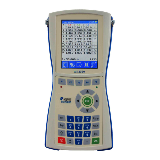
Working Standard User’s Guide 3. Device Hardware Overview 3.1 Front Side Figure 3 – Front side of the device Display Function keys - color graphical display - quick access to functions Impulse LED Indicator of charging of batteries - red LED of impulse output - green LED indicating charging status Alphanumeric keypad Choice keys... -
Page 10: Back Side
Working Standard User’s Guide Available keypad versions: Figure 4 – Latin keypad Figure 5 – Cyrillic keypad 3.2 Back Side Protection Rubber - blue protection rubber Nameplate - nameplate with product information Accumulators box - box for accumulators (4 x AA) Screws of accumulators box Screws of back side of the device Figure 6 –... -
Page 11: Bottom Connectors
Working Standard User’s Guide Figure 7 – Name plate Name plate contains following information: • Device Brand and Model Number • Bar Code containing Serial Number • Serial Number • Year of Manufacture • Accuracy Class • Applicable Standards • CE mark 3.3 Bottom Connectors Figure 8 –... -
Page 12: Top Connectors
Working Standard User’s Guide 3.4 Top Connectors Figure 9 – Top side connectors Signal Input A In A - main signal (voltage or current) input connector Signal Input B In B - main signal (voltage or current) input connector Auxiliary (AUX) Input / Output connector Auxiliary Lighting LED - white LED of auxiliary lighting controlled by SHIFT key Accessories connectable into Auxiliary (AUX) Input / Output connector:... -
Page 13: Power Supply
Working Standard User’s Guide 3.5 Power Supply Caution Accumulators are necessary to regularly charge, because fully discharging of them may lead to their damage. Measurement can be influenced by connected Power Adapter under some circumstances. It is recommended to test meters with charged accumulators without connected Power Adapter. -
Page 14: Locking Mechanism
Working Standard User’s Guide Figure 11 – Plug on the cable of the accessory Figure 10 – Receptacle (socket) Figure 12 – Inserted plug 3.6.1 Locking Mechanism Figure 13 – Pulling on the cable or on the Figure 14 – Pulling on the outer plug housing back nut causes the locking fingers to grip disengages the locking fingers from the receptacle tighter into the groove inside receptacle... -
Page 15: Cable Connecting
Working Standard User’s Guide 3.6.2 Cable Connecting Figure 16 – Connected cable Figure 15 – Connecting 3.6.3 Cable Disconnecting Figure 17 – Figure 18 – Incorrect disconnecting Incorrect disconnecting ✓ Figure 19 – Figure 20 – Incorrect disconnecting Correct disconnecting www.appliedp.com WS-UGFW619-EN... -
Page 16: Device Software Overview
Working Standard User’s Guide 4. Device Software Overview This chapter describes user interface of Working Standard software. * P42 * Screen identification codes (for example ) can be found in captions of all described software screens. 4.1 Initialization * P42 * P41 Device Initialization screen Date &... -
Page 17: Main Screen
Working Standard User’s Guide User has option to enter Demo Mode by pressing OK key or continue operation without entering Demo Mode by pressing any other key. Demo Mode Initialization screen which is shown after entering Demo Mode enables to configure Demo Mode operation. -
Page 18: Text Input
Working Standard User’s Guide 4.4 Text Input Pressing OK button on any selected input field brings device into Text Input Mode in which device shows Keypad Mode indicator instead of actual time below battery state indicator. Text Input Mode Actual Keypad Mode is indicated in upper right corner of the display and can be switched by repeated pressing of SHIFT key Available Keypad Modes: …... - Page 19 Working Standard User’s Guide 4.5 Main Measurement Content of main measurement page depends on type of connected sensors: Load Values ......if one voltage and one current sensor are connected Actual Values I ..... if one current sensor is connected Actual Values U ....
- Page 20 Working Standard User’s Guide Control keys: F1 ..... Energy Values F2 ..... Meter Error Test F3 ....Transformer Test F4 ..... Readout Test F5 ..... Menu ▼▲ ..Scroll Load Values screens: LVa <-> LVa1 <-> LVa2 <-> LVa3 <-> LVa respectively LVb <->...
- Page 21 There are only two versions of Load Values screens in single phase device: * P44 * P69 WS 2120 - Load Values screen WS 2120 - Load Values Primary screen Primary screen shows primary values which depend on CT and VT ratios defined for actual meter. www.appliedp.com WS-UGFW619-EN...
-
Page 22: Actual Values
Working Standard User’s Guide 4.5.2 Actual Values Actual Values screens show actual measured and calculated values of load point when other combination than one current and one voltage measurement sensors are used. Device shows measured and calculated values of Current (CT) and Voltage (VT) Transformers. In case of connection of one measurement sensor device shows: •... - Page 23 Control keys: F1 ....Graphical Presentation screens F3 ....Meter Readout / Swap primary vs secondary sides F4 ....Save F5 ....Menu Actual Values screens for WS 2120: * P60 * P61 One current sensor used One voltage sensor used www.appliedp.com...
- Page 24 Working Standard User’s Guide * P62 * P63 Two current sensors used Two voltage sensors used Control keys: F1 ....Graphical Presentation screens F3 ....Meter Readout / Swap primary vs secondary sides F4 ....Save F5 ....Menu www.appliedp.com WS-UGFW619-EN...
-
Page 25: Graphical Presentation
Graphical Presentation screens for WS 2320: * P03 * P04 * P02 Vector Diagram screen Harmonics screen Curve screen Graphical Presentation screens for WS 2120: * P49 * P50 * P51 Vector Diagram screen Harmonics screen Curve screen Vector diagram has two parameters which can be configured in Measurement Settings:... - Page 26 Working Standard User’s Guide Little back triangle in top right corner in one of the voltage or current values determines the synchronization frequency channel. Harmonics View screen shows measured values (amplitude and phase) of all harmonics. Individual harmonic components are distributed over several screens (3 x I, 3 x U).
- Page 27 Accumulation of these energies can be stopped and started again (key F3) or just restarted by key F4. * P43 Energy Values screen in WS 2320 * P52 Energy Values screen in WS 2120 List of displayed quantities: ΣP ..Sum of Active Powers ΣE ..Sum of Active Energies ΣQ ..
- Page 28 Working Standard User’s Guide 4.6.2 Energy Test This page can be accessed from Load Values screen by F1 followed by F2. Configuration of Energy tests is in Test Settings menu, where mode (Time or Energy), amount of time / energy and energy type (Active, Reactive, Apparent) is specified. Test is initialized by pressing F1 key when device shows message Enter counter #1 which requests user to enter initial state of counter of the meter under test.
- Page 29 Working Standard User’s Guide Content: COUNTERS ..Values of meter counters (registers) Prim. / Sec. switch ..meter measures energy for primary or secondary side of transformer (if applicable). Default state is Sec. #1 ..Value of counter before test #2 ..
- Page 30 Working Standard User’s Guide Workflow of Dial Test: Press F1, press F2 to Dial Test. Press Start. Note: set Energy type: (Active, Reactive, Apparent) Menu >> F2 Test Settings >> Test Settings * P59 Dial Test screen The measurement procedure starts. * P59 Dial Test screen www.appliedp.com...
- Page 31 Working Standard User’s Guide Enter counter #1. Press Start. * P59 Dial Test screen After the End of Measurement enter counter #2 or ∆E. * P59 Dial Test screen www.appliedp.com WS-UGFW619-EN...
- Page 32 Working Standard User’s Guide Device calculate the results. * P59 Dial Test screen Save measurement. * P59 Dial Test screen www.appliedp.com WS-UGFW619-EN...
- Page 33 Working Standard User’s Guide Workflow Dial Test - Reactive: Press F1, press F2 to Dial Test. Press PgDn. Choose Quadrant – choose of Lag(QI+QIII), Lead(QII+QIV), QI+QII, QIII+QIV, QI, QII, QIII, Press Start. Note: set Energy type: (Active, Reactive, Apparent) Menu >> F2 Test Settings >> Test Settings 2/3 set Energy measurement: (4Quadr., Algo1,..) Menu >>...
- Page 34 Working Standard User’s Guide Enter counter #1. Press Start. * P215 Dial Test screen After the End of Measurement enter counter #2 or ∆E. * P215 Dial Test screen www.appliedp.com WS-UGFW619-EN...
- Page 35 Working Standard User’s Guide Device calculate the results. * P215 Dial Test screen Save measurement. * P215 Dial Test screen www.appliedp.com WS-UGFW619-EN...
- Page 36 Working Standard User’s Guide Workflow Dial Test - PQS: Press F1, press F2 to Dial Test. Press PgDn 2x Press Start. Note: set Energy type: (Active, Reactive, Apparent) Menu >> F2 Test Settings >> Test Settings 2/3 set Energy measurement: (4Quadr., Algo1,..) Menu >>...
- Page 37 Working Standard User’s Guide Enter counter #1. Press Start. * P213 Dial Test screen After the End of Measurement enter counter #2 or ∆E. * P213 Dial Test screen www.appliedp.com WS-UGFW619-EN...
- Page 38 Working Standard User’s Guide Device calculate the results. * P213 Dial Test screen Save measurement. * P213 Dial Test screen www.appliedp.com WS-UGFW619-EN...
- Page 39 Working Standard User’s Guide 4.6.3 Maximum Demand Test This page can be accessed from Load Values screen by pressing of F1, followed by F2 and F3. Configuration of MD tests is in Test Settings menu, where Period, Subperiods and Window can be specified.
- Page 40 Working Standard User’s Guide Control keys: F1 ....Start / Stop of the test F2 ....Meter Readout F3 ....Switch to Dial Test Screen (also PgUp key can be used) F4 ....Save results of MD tests F5 ....Menu ESC ....
- Page 41 Working Standard User’s Guide Constant type ..Primary / Secondary – for indirect meters from database, indicates which side of the transformer is referred to the constant of electricity meter. For direct meters the default value is always Secondary and for that case this parameter is not displayed.
-
Page 42: Test Result Details
Working Standard User’s Guide 4.7.1 Test Result Details Measured samples can be seen in Test Result Details page which can be activated by F3 from Meter Error Test page. This screen shows all test parameters and all measured samples with pulses or energies against time used for evaluation of these samples. - Page 43 Working Standard User’s Guide Content: SN ....... Serial number of meter Type ....meter type Connection ..connection type regarding wires number Input Type ..error registration method Energy ....energy type during test Constant .... value of the constant for the selected registration method Constant unit ..
- Page 44 Working Standard User’s Guide 4.8 Constant Detection This page enables to detect the constant of the meter to be verified. Page is activated by PgDn key from Meter Error Test screen. Once the constant is obtained, it is not automatically stored or used elsewhere, user must use the obtained value to enter it in the Meter Error Test screen or elsewhere.
-
Page 45: Transformer Test
Working Standard User’s Guide 4.9 Meter Readout Meter Readout page enables to read content of registers of multifunctional meters with optical communication interface according to IEC 62056-21. Optical Communication head OPTH 1200 has to be connected to AUX input of the device and properly placed to meter under test before starting data readout. - Page 46 Working Standard User’s Guide * P34 * P35 One current sensor One voltage sensor * P33 Transformer Test screen (one voltage sensor and one current sensor used) * P36 * P37 Two current sensors Two voltage sensors Content: U, I ....Load Point values ....
- Page 47 Working Standard User’s Guide Control keys: F1, ESC ..Exit (return to previous page / skipping to next page) F3 ....Burden test F3 ..... Data readout F3 ....Switch primary/secondary selection F4 ..... Save Load Point values (including harmonics and shapes) into results database F5 ....
- Page 48 Working Standard User’s Guide Control keys: F3 ....Transformer test F4 ..... Save Load Point values (including harmonics and shapes) into results database F5 ....Menu 4.12 Menu Menu enables access to settings, database, information about device and device calibration. It can be activated by key F5.
-
Page 49: Measurement Settings
Working Standard User’s Guide 4.12.1 Measurement Settings This page, divided to six screens, contains parameters of measurement mode. * P12 * P13 Meas. Settings screen 1/6 Meas. Settings screen 2/6 Connect. type ......Connection type: 3P4W, 3P3W, 2P3W, 1P3W or 1P2W (see appendix Connection Diagrams). - Page 50 Working Standard User’s Guide RANGE (Input A / Input B) ..Settings of ranges for both measurement inputs (this part of settings is stored in SD card, but only for particular accessory. If other accessory is used, default values will be loaded. Accessory is identified by its serial number) Auto ......
- Page 51 Working Standard User’s Guide Fund. f. … reactive power defined by IEC 62053-24 is reactive power of fundamental harmonic component. This type of reactive power is also defined in IEEE 1459-2010 as fundamental reactive power: �� = �� ∗ �� ∗...
- Page 52 Working Standard User’s Guide * P91 * P201 Meas. Settings screen 5/6 Meas. Settings screen 6/6 VOLTAGE AMPLITUDE ..Settings of voltage drop warnings Check ......Enable (ON) or disable (OFF) checking of voltage amplitude value Threshold ....Value in %, relative to nominal voltage of selected meter to be tested CURRENT AMPLITUDE ..
-
Page 53: Test Settings
Working Standard User’s Guide Control keys: F1, ESC ..Exit (return to previous page) F3 ....Load default values (only for parameters in shown page!) F4 ....Save parameter values of all Measurement Settings screens into memory F5 ....Switching between screens 4.12.2 Test Settings These pages contain parameters of testing mode. - Page 54 Working Standard User’s Guide Always Show ....ON / OFF. When enabled (ON), the Test results details screen will automatically appear after end of meter error test (after registering predefined number of impulses). It is the same like pressing F3 key after test done.
- Page 55 Working Standard User’s Guide * P202 Test Settings screen 3/3 AUTOMATIC SNAPSHOTS ..Setting of Automatic Snapshots routine Period ......how often a snapshot will be taken (in minutes from interval <0.1; 1440>) No. of samples .... how many snapshots will be taken (maximum in DB is limited to 1000) Start ......
-
Page 56: System Settings
Working Standard User’s Guide 4.12.3 System Settings This page is divided into four screens contains general parameters of the system of the device. * P14 * P32 System Settings screen 1/4 System Settings screen 2/4 * P209 * P207 System Settings screen 3/4 System Settings screen 4/4 www.appliedp.com WS-UGFW619-EN... - Page 57 Working Standard User’s Guide Content: Date ........Actual date (in format DD-MM-YYYY) Time ........Actual time (in format HH:MM:SS) Language ......Selection of language of user interface BAUDRATE ....... Settings of baud rate of device communication interfaces: 300, 600, 1200, 2400, 4800, 9600, 19200, 28800, 38400, 57600 or 112000 Bd.
- Page 58 Working Standard User’s Guide 4.12.4 Information Information are distributed over several screens and contain basic information about the device and connected accessories. Calculation of MEMORY USAGE in 3 screen can take few seconds. * P20 * P84 * P25 Information screen 1/3 Information screen 2/3 Information screen 3/3 Content:...
- Page 59 * P33 * P208 you here: you here: you here: * P95 Tests Menu Item no. 7 will require the password to entry into calibration menu. If you need to calibrate the device, please refer to Applied Precision Ltd. www.appliedp.com WS-UGFW619-EN...
- Page 60 Working Standard User’s Guide 4.13 Databases The database screens allow viewing, editing, adding and deleting of tested meters, results of tests, load points and data readouts stored in the internal databases. Every meter (shown in DB 1/5) can have stored more measured meter errors (DB 2/5), stored load point values (DB 3/5), results of energy tests (DB 4/5) and readouts (DB 5/5).
- Page 61 Working Standard User’s Guide 4.13.1 Database of Meters Database of Meters contains all information (parameters) of tested meters. Searching Fields • SN ..serial number • Type ..type of meter Table of Meters • SN ..serial number • TYPE ..type of meter •...
- Page 62 Working Standard User’s Guide 4.13.2 Database of Meter Errors Database contains meter error tests saved for actual meter in Meter Error Test page. Meter Identification • serial number • type of meter Table of Meter Error Tests • No..meter error test number •...
- Page 63 Working Standard User’s Guide Meter Error Test Parameters shown in Table of Parameters of selected test: DATE test date FREQ frequency TIME test time MCURR current (3x) METERERROR test result MVOLT voltage (3x) METERSTDEV standard deviation of result MPHI current phase angle (3x) METERCONST meter constant value MPHU...
- Page 64 Working Standard User’s Guide 4.13.3 Database of Load Values Database contains load point values saved for actual meter in Vector Diagram, Harmonics or Curve pages. Meter Identification • serial number • type of meter Table of Load Points • No..load point number •...
- Page 65 Working Standard User’s Guide Load Point Parameters shown in Table of Parameters of selected load point: DATE test date MDFIXActive; MD power register actualized in fixed time MDFIXReactive; TIME test time window MDFIXApparent MCURR current (3x) MDSlidActive; MD power register MVOLT voltage (3x) actualized in “slided”...
- Page 66 Working Standard User’s Guide 4.13.4 Database of Energy Tests Database contains energy tests results saved for actual meter in Energy Test page. Meter Identification • serial number • type of meter Table of Energy Tests • No..energy test number •...
- Page 67 Working Standard User’s Guide Energy Test Parameters shown in Table of Parameters of selected energy test: DATE test date MPHI current phase angle (3x) TIME test time MPHU voltage phase angle (3x) COUNTERBEGIN initial state of counter MDFI current distortion (3x) COUNTEREND final state of counter MDFU...
- Page 68 Working Standard User’s Guide 4.13.5 Database of Meter Readouts Database contains data readouts made and stored for actual meter. Content: Table of Meter Readouts with columns: - No..Readout number - Time ..Date and time of readout - Length .. Readout length in Bytes Control keys: F1 ..
- Page 69 Working Standard User’s Guide 4.13.6 Adding or Editing Meters Adding of new meter (using key F3) and editing of selected meter parameters (using key F2) are performed on screens with same content only the names of the screens are different. In Editing mode all actual meter parameters are shown in four screens and user can edit any of them and save the changes using F4 key.
- Page 70 Working Standard User’s Guide Meter Parameters shown in Add / Edit Meter screens: SN - serial number - delta to star conversion Frequency - Frequency from meter’s label Type - meter type Connection - connection type Method - method of registering bidirectional energy flow (Algo0-Algo4) Input type - mark type PROTOCOL TEXTS...
- Page 71 Working Standard User’s Guide 4.13.7 Deleting Database Items Any database item can be deleted using F4 key. Deleting requires confirmation (F5) from user on one of below screens. Deleting all meters (whole database) can be done using F3 key on screen for deleting of one selected meter.
- Page 72 Working Standard User’s Guide * P18 Delete Meter Readout Control keys: F1, ESC ..Termination without meter deleting F3 ....Deleting of all meters/snapshots F5 ....Deleting of selected meter www.appliedp.com WS-UGFW619-EN...
-
Page 73: Test Report
This device, for CONSTANT: 375r/kWh instance a PC, has to be equipped with standard CLASS: serial bus. Test report contains: CUSTOMER: Applied Precision ADDRES: Stavitelska 1, Bratislava date of measurement parameters of tested meter NOTE1:... -
Page 74: Remote Interface
Driver can be found also in internet: Newest version of required driver is available from FTDI website: http://www.ftdichip.com/Drivers/VCP.htm Maybe not actual but tested version of driver is available in Applied Precision’s website from link: http://www.appliedp.com/download/driver/ftdi-vcp.zip Driver Installation If windows ask for driver … navigate to driver subdirectory on supplied CD / USB key If driver downloaded from internet …... -
Page 75: Firmware Upload
Working Standard User’s Guide 5.2 Firmware Upload Firmware (= Device Software) can be upgraded using software utility Firmware Upload - USB available on supplied CD / USB key (typically in directory \WS\SERVICER) or from internet link: http://www.appliedp.com/download/software/servicer/fwuploadusb/fwuploadusb_sw.zip Firmware Upload - USB is single file standalone utility which doesn’t require installation. Firmware Upload –... -
Page 76: Remote Communication
Working Standard User’s Guide 5.3 Remote Communication Device control, results readout and measured values collection remotely is performed using device commands compatible with SCPI standard (Standard Commands for Programmable Instruments). Main rules of SCPI standard: • parentheses { } restrict parameter in the command strain •... -
Page 77: System Related Commands
Working Standard User’s Guide System Related Commands SYST:SERN? Request for the device serial number. SYST:VERS? Request for the device firmware version (FW1). SYST:VFW2? Request for the device firmware version (FW2). SYST:VGUI? Request for the device GUI version. SYST:VHW1? Request for the device hardware version (HW1). SYST:VHW2? Request for the device hardware version (HW2). -
Page 78: Impulse Output
Working Standard User’s Guide SYST:SET:COM2? Request for actual settings of USB serial communication. See command SYST:SET:COM? SYST:SET:COM2 {<baudrate (300-115200)>} Setting parameters of USB serial communication. See command SYST:SET:COM? SYST:CONF:SAV Save configuration. SYST:CONF:LOAD Load user configuration. SYST:CONF:LOAD:DEF Load default configuration (from FW version 4.03). SYST:UIC? Request for the state of checking (voltage) unconnected input. - Page 79 Working Standard User’s Guide SYST:ENER:ALG {<algorithm>} Setting of the method of summing energy. Parameter can be 0 = 4Quadrant, 1 = Algo1 (Net Result), 2 = Algo2 (Positive Aggregate), 3 = Algo3 (Both Sum), 4 = Algo4 (Anti-fraud). SYST:ENER:SENS? Request for the setting of energy direction during summing energy. Only for Algorithm different from 4Quadrant (see SYST:ENER:ALG command).
- Page 80 Working Standard User’s Guide SYST:ENER:IMP:MOD? Request for the state of the device impulse output. Reply is number: 0 … state is FIXED, 1 … state is ACTIVE POWER, 2 … state is REACTIVE POWER, 3 … state is APPARENT POWER SYST:ENER:IMP:MOD {<mode>} Setting the state of device’s impulse output.
- Page 81 Working Standard User’s Guide SYST:ENER:DOS:TYP {<type>} Setting of Dosage Type. Parameter is 0 for time or 1 for energy. SYST:ENER:DOS:TYP? Request for state of Dosage Type. Answer is 0 for time or 1 for energy. SYST:ENER:DOS:TIM {<time>} Setting of time (in seconds) for time dosage. SYST:ENER:DOS:TIM? Request for time for “time dosage”.
- Page 82 Working Standard User’s Guide SYST:ENER:DOS:MAXD:SUBP {<subperiod>} Setting the value of Maximum Demand Test’s sub-period parameter. SYST:ENER:DOS:DUT:MAXD:K {<register>} Setting the register value of Maximum Demand Test for DUT (Device Under Test). SYST:ENER:DOS:RES:MAXD? Request for error of Maximum Demand Test after finishing this test. SYST:ENER:DOS:STAT:MAXD:K? Request for state of Maximum Demand Test.
- Page 83 Working Standard User’s Guide Meter Testing Commands SYST:TST:STOP Stop meter testing SYST:TST:STAR Start meter testing SYST:TST:STAR? SYST:TST:STAT? Both commands (same behavior) return meter testing state: 0 = not running, 1 = running SYST:TST:STAT:COUN? Returns number of already measured samples SYST:TST:RES? { [<count>] } If parameter is omitted (not used) then returned value is average value from all measured samples (when measurement is finished then this value is result of measurement).
- Page 84 Working Standard User’s Guide Sets number of impulses (OPS predivider). Used only when testing mode (command SYST:TST:MOD) is set to 1. SYST:TST:IMP:STAT? Request for state of impulses counting. Returned value: -1 … not valid (synchronization) impulse, 0 – x … number of impulses captured. SYST:TST:IMP:STAT:MAX? Request for number of impulses for one sample.
- Page 85 Working Standard User’s Guide Measuring Accessory Related Commands Commands to read out serial numbers and types of measuring accessory connected to the device. SYST:INPA:SERN? Request for the serial number of accessory connected to Input A (In A). SYST:INPA:TYPE? Request for the type of accessory connected to Input A (In A). SYST:INPB:SERN? Request for the serial number of accessory connected to Input B (In B).
-
Page 86: Measurement Commands
Working Standard User’s Guide Measurement Commands Measurement commands return measured values in form of a set of three real numbers without unit. Values are in classic or exponential format (depends on value and firmware version) with max. 6 decimal places and separation of decimal part of number is made by point. Three values are separated by comma or comma followed by space (depends on firmware version). - Page 87 Working Standard User’s Guide Setting the auto range in accessory connected to input A. Parameter is: 0 = OFF, 1 = ON. CHNLB:AC:RANG? Request for the range in accessory connected to input B. Answer can be 0, 1 … (up to supported number of ranges). CHNLB:AC:RANG {<range>} Setting the measurement range in accessory connected to input B.
- Page 88 Working Standard User’s Guide MEAS:CURR:AC:PHAS? Request for phases between current and voltage in each phase. MEAS:CURR:AC:SUM:SQ? Request for sum of square currents. MEAS:CURR:AC:DIST? Request for the distortion of measured current. MEAS:CURR:AC:TR:RAT Transformer Test: Request for the measured transmission ratio of separate current channels (r Lx/L1 MEAS:CURR:AC:TR:ERR Transformer Test: Request for the calculated transmission error of separate current channels (er...
- Page 89 Working Standard User’s Guide MEAS:POW:AC:APP:PRIM? Request for primary apparent power values. MEAS:POW:AC:FACT? Request for power factors. MEAS:POW:AC:SUM:ACT? Request for sum of active powers. MEAS:POW:AC:SUM:ACT:PRIM? Request for sum of primary active powers. MEAS:POW:AC:SUM:REAC? Request for sum of reactive powers. MEAS:POW:AC:SUM:REAC:PRIM? Request for sum of primary reactive powers. MEAS:POW:AC:SUM:APP? Request for sum of apparent powers.
- Page 90 Working Standard User’s Guide MEAS:FREQ:MOD:CHAN {<mode>} Setting of channel of frequency measurement. Parameter is 0 (auto), 1 – 6 (channel). MEAS:ENER:STAR Start of energy accumulation (if stopped). MEAS:ENER:STOP Stop of energy accumulation (if started). MEAS:ENER:RES Reset (clearing to zero) of energy accumulation values. MEAS:ENER:STAT? Request for status of energy accumulation.
- Page 91 Working Standard User’s Guide MEAS:ENER:REAC:CHAN? {<channel (0|1|2)>} Request for reactive energy values in vars in particular channel. Parameter channel can be 0=L1, 1=L2, 2=L3. MEAS:ENER:REAC:CHAN:PRIM? {<channel (0|1|2)>} Request for primary reactive energy values in vars in particular channel. Parameter channel can be 0=L1, 1=L2, 2=L3.
- Page 92 Working Standard User’s Guide Request for measured samples of the waveform. Returns first 64 values from specific channel (phase (0=L1, 1=L2, 2=L3), unit (0=U, 1=I)). Answer: amplitude samples (64 comma separated real numbers). MEAS:SIGN:AMPL? {<phase (0|1|2)>},{< unit (0|1)>} Request for measured amplitude values of higher harmonic content. Returns first 40 values from specific channel (phase (0=L1, 1=L2, 2=L3), unit (0=U, 1=I)).
- Page 93 Working Standard User’s Guide MEAS:CHNLB:MOD? Request for accessories type connected to Input B. Answer can be: 2 … voltage, 1 … current, 0 … none. MEAS:VAL:CONF {<xHI>},{<xLO>} This command allows to set the mask based on which MEAS:VAL? returns values. This command accepts decimal values and also hexadecimal using 0x prefix.
- Page 94 Working Standard User’s Guide 0x0000008000000000 0x0000010000000000 Reactive Energy 0x0000020000000000 0x0000040000000000 Eq123 L123 0x0000080000000000 0x0000100000000000 Active Energy 0x0000200000000000 0x0000400000000000 Es123 L123 0x0000800000000000 Upp12 L1-L2 0x0001000000000000 Upp23 L2-L3 Voltage between phases 0x0002000000000000 Upp31 L3-L1 0x0004000000000000 phUpp1223 L12-L23 0x0008000000000000 phUpp2331 L23-L31 Phase Shift of phase voltage 0x0010000000000000 phUpp3112 L31-L12 0x0020000000000000 Phase Sequence of voltage...
- Page 95 Working Standard User’s Guide MEAS:MAXD:K? Request for final result of Maximum Demand Test. MEAS:MAXD:K:TEMP? Request for actual (temporary) value of Maximum Demand Test. MEAS:MAXD:WIN:BEG? Request for timestamp of the beginning of Maximum Demand Test window. MEAS:MAXD:WIN:END? Request for duration of Maximum Demand Test window. MEAS:MAXD:RES Resets Maximum Demand Test.
- Page 96 Working Standard User’s Guide 6. APPENDIX www.appliedp.com WS-UGFW619-EN...
-
Page 97: Connection Diagrams
Working Standard User’s Guide 6.1 Connection Diagrams 6.1.1 SINGLE PHASE measuring accessories Single-phase 2-wire (1P2W) connection 6.1.2 TWO PHASE measuring accessories Single-phase 3-wire (1P3W) or Single-phase 2-wire (1P2W) connection two-phase 3-wire (2P3W) connection www.appliedp.com WS-UGFW619-EN... - Page 98 Working Standard User’s Guide 6.1.3 THREE PHASE measuring accessories Single-phase 3-wire (1P3W) connection Single-phase 2-wire (1P2W) connection Two-phase 3-wire (2P3W) connection www.appliedp.com WS-UGFW619-EN...
- Page 99 Working Standard User’s Guide Three-phase 3-wire (3P3W) connection with Current Clamps Three-phase 3-wire (3P3W) connection with Current Transducer www.appliedp.com WS-UGFW619-EN...
- Page 100 Working Standard User’s Guide Three-phase 4-wire (3P4W) connection with Current Clamps Three-phase 4-wire (3P4W) connection with Current Transducer www.appliedp.com WS-UGFW619-EN...
- Page 101 Working Standard User’s Guide 6.2 Aggregate Energy Calculation Methods www.appliedp.com WS-UGFW619-EN...
-
Page 102: Overvoltage Categories
LED can be used in a same way as any regular electricity meter, i.e. with specific sensor. Optionally a pulses divider (supplied by Applied Precision) can be used to lower the pulses rate if the WS’s constant modification is not enough to fulfill the possible reference’s maximum pulses limitation that may be present (e.g. -
Page 103: Measurement Time
Working Standard User’s Guide 6.5 Measurement Time Measurement Time (time needed for new sample) is defined by Integration Time, which is stated in Test Settings of device. If time between marks / impulses from the meter under test is longer than Integration Time then Measurement Time is equal to time between capturing marks from the meter. - Page 104 Working Standard User’s Guide 6.6.1 Voltage or Ratio Error in Voltage Transformer According to IEC 60044-2 standard Rated Transformation Ratio The ratio of the rated primary voltage to the rated secondary voltage Voltage Error (Ratio Error) The error which a transformer introduces into the measurement of a voltage and which arises when the actual transformation ratio is not equal to the rated transformation ratio [IEV 321-01-21 modified] The voltage error expressed in per cent is given by the formula:...
-
Page 105: Maintenance
Working Standard User’s Guide 6.7 Maintenance Caution To guarantee correct operation of the device: • Do not use the Product outside its operational temperature range. • Ensure that all cables are in good condition. • Use special (included) plugs that make a firm, secure connection to the Product’s output binding posts. -
Page 106: Declaration Of Conformity
Working Standard DECLARATION OF CONFORMITY Manufacturer’s Name: Applied Precision Ltd. Manufacturer’s Address: Stavitelska 1 831 04 Bratislava SLOVAKIA Declares, that the product Product Name: Working Standard Model Number(s): WS 2120A, WS 2120B, WS 2120C WS 2320A, WS 2320B, WS 2320C...
Need help?
Do you have a question about the WS 2120 and is the answer not in the manual?
Questions and answers