Table of Contents
Advertisement
Advertisement
Table of Contents

Related Manuals for Applied Precision ISOMET 2114


Summary of Contents for Applied Precision ISOMET 2114
- Page 1 ISOMET 2114 Thermal properties analyzer User’s Guide Version 1.46...
- Page 2 ISOMET 2114 User’s Guide Contents Safety Considerations and Instructions ................3 Introduction ..........................4 2.1 Description ..........................4 2.2 PRINCIPLE OF OPERATION ....................5 2.2.1 Measurement Probes ......................5 2.2.2 Accuracy Influencing Factors .................... 5 2.3 Measuring System ........................6 Measuring Unit ........................
-
Page 3: Safety Considerations And Instructions
ISOMET2114 User’s Guide 1. Safety Considerations and Instructions Basic safety instructions The unit is dedicated for hand-held operation with strictly limited conditions for connecting to circuits with non-safe potential level referring to IEC EN 61010. Keep the operational conditions defined in technical specification. ... -
Page 4: Introduction
[ °C ] Temperature ISOMET 2114 is a hand-held measuring instrument for direct measurement of heat transfer properties of a wide range of isotropic materials including cellular insulating materials, plastics, glasses and minerals. It is equipped with two types of measurement probes: needle probes for soft materials, surface probes for hard materials. -
Page 5: Principle Of Operation
ISOMET2114 User’s Guide 2.2 PRINCIPLE OF OPERATION Measurement is based on analysis of the temperature response of the analyzed material to heat flow impulses. Heat flow is excited by electrical heating of resistor heater inserted into the probe which is in direct heat contact with the tested specimen. -
Page 6: Measuring System
ISOMET 2114 User’s Guide 2.3 Measuring System Measuring system of ISOMET 2114 consists of Measuring Unit, optional Needle and Surface type measurement probes supported with following accessories: Standard Accessories Optional Accessories Needle Probe with one meas. ISOMET 2114 Measuring Unit... -
Page 7: Measuring Unit
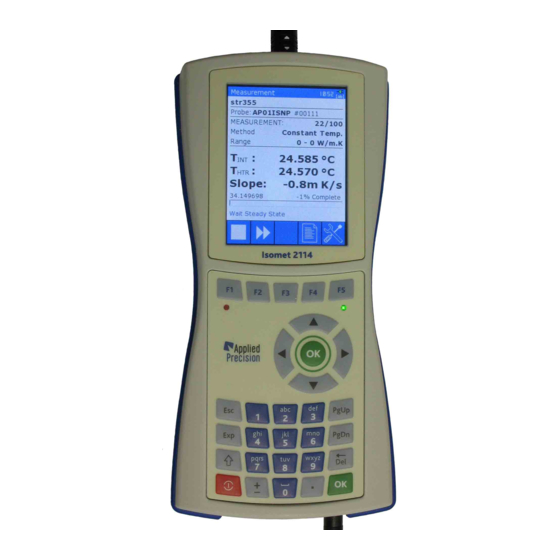
ISOMET2114 User’s Guide 3. Measuring Unit 3.1 Front panel Front panel of the device Display Function keys - colour graphical display - quick access to functions Indicator of charging batteries - indicates enabled heating - green LED indicating charging status Alphanumeric keypad Choice keys - keys 0-9 (a-z) -
Page 8: Rear Panel
ISOMET 2114 User’s Guide 3.2 Rear panel Back panel of the device Protection Rubber - blue protection rubber Nameplate - nameplate with serial number Accumulators box - box for accumulators (4 x AA) Screws of accumulators box Screws of back side of the device... -
Page 9: Bottom Connectors
- connector of power adapter (+12V) 3.4 Measurement Probes ISOMET 2114 is supplied with various types of measurement probes. Calibration coefficients and further technical parameters are written into the probe nonvolatile memory, which ensure interchangeability of probes. These parameters are uploaded into the measurement unit during initialization procedure after switching the measuring unit on. -
Page 10: Locking Mechanism
ISOMET 2114 User’s Guide 3.4.1 Locking Mechanism Pulling on the cable or on the back nut causes Pulling on the outer plug housing disengages the the locking fingers to grip tighter into the groove locking fingers from the receptacle groove and inside receptacle (socket). -
Page 11: Cable Disconnecting
ISOMET2114 User’s Guide 3.4.3 Cable Disconnecting Incorrect disconnecting Incorrect disconnecting Incorrect disconnecting Correct disconnecting 3.5 Power Supply ISOMET2114 is powered by 4 pieces of AA sized 1.2 V rechargeable batteries. Batteries are installed under the plastic cover on the rear panel of the instrument. External power adapter with range of input voltage from 100VAC to 240V, 50-60Hz is supplied for recharging batteries. - Page 12 ISOMET 2114 User’s Guide Batteries Charger Status is indicated by means of the green LED, situated on the front panel keyboard under key F5. Batteries Charger Status LED has three statuses: no light ..... power adapter (charger) not connected flashing ....batteries are charging steady light ....
-
Page 13: Operation
User’s Guide 4. Operation Measuring unit of ISOMET 2114 is equipped with color 3.5″ TFT LCD display, alpha-numeric keyboard, USB and RS232 communication ports, which ensure its simple operation. Switching on and switching off the device is done by pressing the red Power key for approx. 3 seconds. -
Page 14: Measurement
ISOMET 2114 User’s Guide 4.1 Measurement After switching the measuring unit on and uploading parameters from the connected probe, Stand by Page containing serial number of the connected probe is shown on the display. After short initialization procedure, continuous temperature measurement is activated by means of two temperature sensors installed in the measurement probe. - Page 15 ISOMET2114 User’s Guide Measurement page Measurement STOP page It is recommended to configure the instrument for repeated thermal conductivity measurement. Results of completed thermal conductivity measurements are available any time also during measurement in progress. Results page for reviewing results may be activated on Measurement, Stand By or menu page by pressing the key F4.
-
Page 16: Results
ISOMET 2114 User’s Guide 4.2 Results The database screens allow reviewing and deleting measurement results Results page Deleting result record Control keys: F2 ........ switching to measurements of selected test F5 ........ deleting selected test results ▼▲ ......scrolling results OK ....... -
Page 17: Menu
ISOMET2114 User’s Guide 4.3 Menu Menu enables access to settings, database of measurement results, information about device and device calibration. It can be activated by pressing the key F5 on Stand By page. Menu page Content: 1. Measurement Settings ....measurement settings 2. -
Page 18: Measurement Settings
ISOMET 2114 User’s Guide 4.3.1 Measurement Settings Measurement Settings page enables selection of measurement range of connected probe with more than one range. Generally, data are entered into the system by means of combo boxes and edit boxes. First the controlling element has to be selected by means of arrows on the keyboard. -
Page 19: Test Settings
ISOMET2114 User’s Guide 4.3.2 Test Settings Test Settings page enables configuring number of repeated measurement, pause between measurements and entering three measurement labels to identify the series of repeated measurements. Editing of edit boxes is described in section 4.3.1. When any of the edit boxes is selected, keyboard mode may be modified for typing upper case letters or numbers by pressing the Shift key. -
Page 20: System Settings
ISOMET 2114 User’s Guide 4.3.3 System Settings System Settings page contains general parameters of the system of the device. Page is showed in two screens and switching between them is done by key F5. System Settings screen 1/2 System Settings screen 2/2 Content: Date ........ -
Page 21: Information Screen
ISOMET2114 User’s Guide 4.3.4 Information Screen Information screen shows basic information about the device and connected accessories. Page is showed in two screens and switching between them is done by the key F5. Information screen ½ Information screen 2/2 Content: DEVICE ........ -
Page 22: Calibration
ISOMET 2114 User’s Guide 4.3.5 Calibration Supplied measurement probes have good long term stability through the whole measurement range. Periodic calibration before measurements is not necessary. Nevertheless, calibration by means of a reference material is supported by the instrument. Calibration coefficient k stated in sense of the standard ASTM –... -
Page 23: Software Data Exchange
ISOMET2114 User’s Guide 5. Software data exchange Measurement results may be transferred from memory of the measuring unit of ISOMET2114 into a personal computer via USB communication interface. Supporting software is supplied with ISOMET2114 on USB MSD (USB key) in two application files: CDM20814_Setup.exe and ResReadout_I2114.exe. - Page 24 ISOMET 2114 User’s Guide After selecting the proper communication port the window will change as follows Proper communication between the PC and the measuring unit Isomet2114 may be checked by clicking on the blue circle arrow, which will upload and display type and serial number of the connected measuring unit with number of detected test results.
- Page 25 ISOMET2114 User’s Guide One complete measurement record has 45 items. Since most of these items are for diagnostics purposes only, the supplied program ResReadout_I2114.exe enables to filter out not wished items from measurement records by using the "filter" check box and key. After clicking on the “filter” key, Filter Settings window will be opened with names of all 45 items.
- Page 26 ISOMET 2114 User’s Guide Transferring results is completed after clicking on the OK button in the Information window with the message “Data successfully loaded” Transferred results are saved in the text file “resNNNN_YYYYMMDDHHMMSS,csv”, in the selected directory. Symbols in the filename are: NNNN –...
- Page 27 ISOMET2114 User’s Guide Data structure in the file “resNNNN_YYYYMMDDHHMMSS,csv” CSV extension of the results file serves to open the file in standard spreadsheets and data analysis software. Measurement results are recorded in rows. Items of a measurement record are organized in columns.
- Page 28 ISOMET 2114 User’s Guide 6. Quick reference for making the first measurement 1. Connect the measuring unit ISOMET2114 to the supplied adapter and connect the adapter to proper mains, according to technical data on the label of the power adapter.
-
Page 29: Technical Specification
ISOMET2114 User’s Guide Technical Specification Measured Quantities - Thermal conductivity ( W / m - Volume heat capacity ( J / m ( °C ) a - Thermal diffusivity / s ) T - Temperature Measurement Ranges Thermal Conductivity Volume Heat Capacity Temperature... -
Page 30: Declaration Of Conformity
ISOMET 2114 User’s Guide DECLARATION OF CONFORMITY Manufacturer’s Name: Applied Precision Ltd. Manufacturer’s Address: Stavitelska 1 831 04 Bratislava SLOVAKIA Declares, that the product Product Name: ISOMET2114 Product Option(s): all options of the above product Conforms with the following European Directives:...
Need help?
Do you have a question about the ISOMET 2114 and is the answer not in the manual?
Questions and answers