Table of Contents
Advertisement
Step Motor Controller
¡Parallel I/O
¡Step motor (Servo/24 VDC)
¡Number of step data: 64 points
Step data input type
JXC51
JXC51
JXC5
JXC5
JXC
JXC
JXC
JX
J J J X
JXC51/61
XC51/
XC51/6
C51/61
C51/6
51/61
1/61
1/61
/61
61
61
Se
Series
S S e
¡Step motor (Servo/24 VDC)
¡Number of step data: 64 points
New
New
A controller with STO sub-function
has been added.
¡Product certification obtained by a third party
(EN 61508 SIL 3, EN 62061 SIL CL 3,
EN ISO 13849-1 Cat. 3 PL e)
¡EN 61800-5-2 STO (Safe Torque Off) function
EtherCAT
direct input type
JXCE1
Series
Applicable network
DeviceNet
®
direct input type
JXC
J J J X
JXC
JX
JXC
JXCD1
XCD
XCD
XCD
CD1
CD1
CD1
D1
D1 1
Se
S S e
Series
s
Applicable network
JXC
Series
EtherNet/IP™
direct input type
e
JXC91
Series s
Applicable network
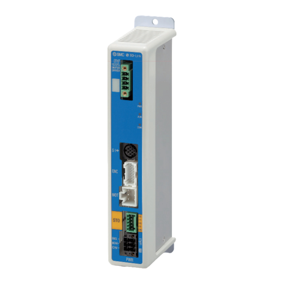
IO-Link
direct input type
e e e
J J J X
JX
JX X C
JXCL1
XCL
XC
CL1
CL1
CL
L1
L1 1
Series
Ser
Se
S S e
eries
Applicable network
JXCLF
Series
PROFINET
direct input type
JXCP1
1 1 1 1 1
Applicable network
CC-Link
direct input type
JXCM1
Applicable network
CAT.EUS100-141B-UK
∗ Excluding
the JXCLF
Se
Ser
Se
Serie
Series
Series
Series
Series
eries
Series
Advertisement
Table of Contents

Related Manuals for SMC Networks JXC Series


Summary of Contents for SMC Networks JXC Series
- Page 1 Step Motor Controller ∗ Excluding ¡Parallel I/O the JXCLF ¡Step motor (Servo/24 VDC) ¡Number of step data: 64 points Step data input type JXC51/61 J J J X JXC5 JXC5 JXC51 JXC51 XC51/ XC51/6 C51/6 C51/61 51/61 1/61 1/61 Series S S e ¡Step motor (Servo/24 VDC) ¡Number of step data: 64 points...
- Page 2 Step Motor Controller Series Step Data Input Type JXC51/61 Series Simple setting allows for immediate use! “Easy Mode” for simple setting For immediate use, select “Easy Mode.” JXC51/61 <When a PC is used> Controller setting software Jogging ¡ Step data setting, test drive, jogging, and move for the Start testing constant rate can be set and...
- Page 3 Step Motor Controller Series “Normal Mode” for detailed setting Select “Normal Mode” when detailed setting is required. ¡Step data can be set in detail. ¡Parameters can be set. ¡Signals and terminal status can be monitored. ¡JOG and constant rate movement, return to origin, test drive, and testing of forced output can be performed. <When a PC is used>...
- Page 4 Step Motor Controller Series Fieldbus Network EtherCAT/EtherNet/IP™/PROFINET/ ® DeviceNet /IO-Link/CC-Link Direct Input Type Step Motor Controller/JXC Series With sub- function JXCE1 JXC91 JXCP1 JXCD1 JXCL1 JXCLF C LF JXCM1 Two types of operation command Transition wiring of communication cables Step no. defi ned operation: Operate using the preset Two communication ports are provided.
- Page 5 Step Motor Controller Series Controller with STO Sub-Function JXC F Series Safety function/STO, SS1-t (EN 61800-5-2) When the STO signal is input from the safety device, after the SS 1 -t operation is completed, the unit shifts to the STO operation and the power supply of the motor is turned OFF. SS1-t operation: Safe Stop 1—After deceleration, a shift to the Speed STO operation occurs.
- Page 6 Step Motor Controller Series System Construction/General Purpose I/O Provided by the customer Electric actuator/ Slider type Power supply for I/O signal 24 VDC I/O cable ∗ Controller Part no. LEC-CN5- Web Catalogue To the parallel I/O connector ∗ Actuator cable Compatible encoder Battery-less Incremental...
- Page 7 Step Motor Controller Series System Construction/Fieldbus Network (EtherCAT/EtherNet/IP™/PROFINET/DeviceNet ® /IO-Link/CC-Link Direct Input Type) LEY/LEYG Electric actuator Series Series LEKFS Series Series Actuator cable 23, 24 LEPY/LEPS Series Series Compatible encoder Battery-less Incremental LESYH Series Series absolute Cable type LES/LESH Series Series Standard cable LE-CP- -S...
-
Page 8: Table Of Contents
CONTENTS Controller (Step Data Input Type) JXC51/61 Series ………………………………………………………………………… How to Order p. 8 ………………………………………………………………………… Specifications p. 8 ………………………………………………………………………… How to Mount p. 9 ………………………………………………………………………… Dimensions p. 10 ………………………………………………………………… Wiring Example p. 11 ……………………………………………………………… Step Data Setting p. 12 ……………………………………………………………………… Signal Timing p. -
Page 9: Controller (Step Data Input Type) Jxc51/61
Controller (Step Data Input Type) JXC51/61 Series How to Order JXC 5 1 7 1 Parallel I/O type Mounting I/O cable length [m] Actuator part number — Screw mounting None Without cable specifi cations and actuator options ∗ DIN rail Example: Enter “LEFS25B-100”... -
Page 10: How To Mount
JXC51/61 Series How to Mount a) Screw mounting (JXC 17 - ) b) DIN rail mounting (JXC 18 - ) (Installation with two M4 screws) (Installation with the DIN rail) DIN rail is locked. Ground Ground wire Ground wire wire Mounting direction DIN rail Mounting direction... -
Page 11: Dimensions
JXC51/61 Series Controller (Step Data Input Type) Dimensions Ø 4.5 For body mounting (Screw mounting) Actuator part number label ∗ Mountable on DIN rail (35 mm) (91.7) 17.3 For body mounting (Screw mounting) -
Page 12: Wiring Example
JXC51/61 Series Wiring Example ∗ When you connect a PLC to the parallel I/O connector, use the I/O cable (LEC-CN5- ). Parallel I/O Connector ∗ The wiring changes depending on the type of parallel I/O (NPN or PNP). Wiring diagram JXC61 (PNP) JXC51... -
Page 13: Step Data Setting
JXC51/61 Series Controller (Step Data Input Type) Step Data Setting 1. Step data setting for positioning 2. Step data setting for pushing In this setting, the actuator moves toward and stops at the The actuator moves toward the pushing start position, and target position. -
Page 14: Signal Timing
JXC51/61 Series Signal Timing Return to Origin 24 V SVON Input SETUP BUSY SVRE SETON Output ∗ALARM ∗ESTOP 0 mm/s Speed Return to origin If the actuator is within the “In position” range of the basic parameter, INP will turn ON, but if not, it will remain OFF. ∗... -
Page 15: Actuator Cable
JXC51/61 Series Controller (Step Data Input Type) Actuator Cable [Robotic cable, standard cable for step motor (Servo/24 VDC)] Controller side LE-CP- /Cable length: 1.5 m, 3 m, 5 m LE CP Connector C (14.2) (Terminal no.) Actuator side (Terminal no.) Cable length (L) [m] (13.5) Connector A... -
Page 16: Options: Actuator Cable
JXC51/61 Series Options: Actuator Cable [Robotic cable for battery-less absolute (Step motor 24 VDC)] LE CE Connector A (14.2) Connector C Cable length (L) [m] (Terminal no.) Connector B (Terminal no.) (13.5) 8 ∗ 10 ∗ 15 ∗ Connector D (10) 20 ∗... -
Page 17: Options
JXC51/61 Series Controller (Step Data Input Type) Options JXC-CPW Communication cable for controller setting Power supply plug ∗ The power supply plug is an accessory. q Communication cable JXC-W2A-C <Applicable cable size> AWG20 (0.5 mm ), cover diameter 2.0 mm or less 1 C24V 4 0V 2 M24V... -
Page 19: Step Motor Controller Jxce1/91/P1/D1/L /M1
Step Motor Controller ∗ Excluding the JXCLF JXCE1/91/P1/D1/L /M1 Series How to Order Communication protocol With STO Standard sub-function EtherCAT — EtherNet/IP™ — PROFINET — DeviceNet ® — IO-Link CC-Link — Number of axes, Special specifi cation 1 axis, Standard 1 axis, With STO sub-function Mounting Screw mounting... -
Page 20: Specifi Cations
JXCE1/91/P1/D1/L /M1 Series Specifi cations JXCE1 JXC91 JXCP1 JXCD1 JXCL1 JXCLF JXCM1 Model ® Network EtherCAT EtherNet/IP™ PROFINET DeviceNet IO-Link CC-Link Compatible motor Step motor (Servo/24 VDC) Power voltage: 24 VDC ±10% Power supply Current consumption (Controller) 200 mA or less 130 mA or less 200 mA or less 100 mA or less... -
Page 21: Dimensions
JXCE1/91/P1/D1/L /M1 Series Step Motor Controller Dimensions JXCE1/JXC91 JXCE1 JXC91 (11.5) Ø 4.5 For body mounting 32.5 Ø 4.5 32.5 (Screw mounting) ∗ Mountable on DIN rail (35 mm) 17.5 17.5 For body mounting For body mounting (Screw mounting) (Screw mounting) JXCP1/JXCD1 JXCP1 JXCD1... - Page 22 JXCE1/91/P1/D1/L /M1 Series Dimensions JXCL1 (11.5) Ø 4.5 For body mounting 32.5 (Screw mounting) ∗ Mountable on DIN rail (35 mm) 17.5 For body mounting (Screw mounting) JXCM1 Ø 4.5 32.5 For body mounting (Screw mounting) Actuator part number label ∗...
- Page 23 JXCE1/91/P1/D1/L /M1 Series Step Motor Controller Dimensions JXCLF (11.5) 32.5 DIN rail mounting adapter 17.5 DIN rail 12.5 5.25 AXT100-DR- (Pitch) ∗ For , enter a number from the No. line in the table below. Refer to the dimension drawings on pages 20 to 22 for the mounting dimensions.
-
Page 24: Actuator Cable
JXCE1/91/P1/D1/L /M1 Series Actuator Cable [Robotic cable, standard cable for step motor (Servo/24 VDC)] Controller side LE-CP- /Cable length: 1.5 m, 3 m, 5 m LE CP Connector C (14.2) (Terminal no.) Actuator side (Terminal no.) Cable length (L) [m] (13.5) Connector A (14.7) -
Page 25: Options: Actuator Cable
JXCE1/91/P1/D1/L /M1 Series Step Motor Controller Options: Actuator Cable [Robotic cable for battery-less absolute (Step motor 24 VDC)] LE CE Connector A (14.2) Cable length (L) [m] Connector C (Terminal no.) Connector B (Terminal no.) (13.5) 8 ∗ 10 ∗ 15 ∗... -
Page 26: Options
JXCE1/91/P1/D1/L /M1 Series Options Communication cable for controller setting Teaching box Enable switch q Communication cable JXC-W2A-C LEC T1 3 J G (Option) Stop Teaching switch Cable length [m] 3000 Enable switch ∗ It can be connected to the controller directly. —... - Page 27 JXCE1/91/P1/D1/L /M1 Series Step Motor Controller Options JXC-CPW JXC-CSTO Power supply plug STO signal plug ∗ The power supply plug is an accessory. 1 C24V 4 0V 2 M24V 5 N.C. 3 EMG 6 LK RLS Power supply plug STO signal plug Terminal name Function Details...
-
Page 28: Jxcl1
Series Precautions Relating to Differences in Controller Versions As the controller version of the JXC series differs, the internal parameters are not compatible. If using the JXC 1 -BC, please use the latest version of the JXC-BCW (parameter writing tool). - Page 29 Precautions Relating to Differences JXC51/61/E1/91/P1/D1/L /M1 Series in Controller Versions Blank Controller Versions and Applicable Battery-less Absolute Type Electric Actuator Sizes The applicable battery-less absolute type electric actuator size range differs depending on the controller version. Be sure to confi rm the controller version before using a blank controller. Blank Controller Versions/Applicable Electric Actuator Sizes Blank controller Applicable electric actuator size...
- Page 30 These safety instructions are intended to prevent hazardous situations and/or equipment Safety Instructions damage. These instructions indicate the level of potential hazard with the labels of “Caution,” “Warning” or “Danger.” They are all important notes for safety and must be followed in addition to International Standards (ISO/IEC) , and other safety regulations.
- Page 31 Revision History Edition B - The JXCLF series controller with STO sub-function has been added. - Number of pages has been increased from 24 to 31. SMC Corporation (Europe) Austria +43 (0)2262622800 www.smc.at offi ce@smc.at Lithuania +370 5 2308118 www.smclt.lt info@smclt.lt Belgium +32 (0)33551464...
Need help?
Do you have a question about the JXC Series and is the answer not in the manual?
Questions and answers