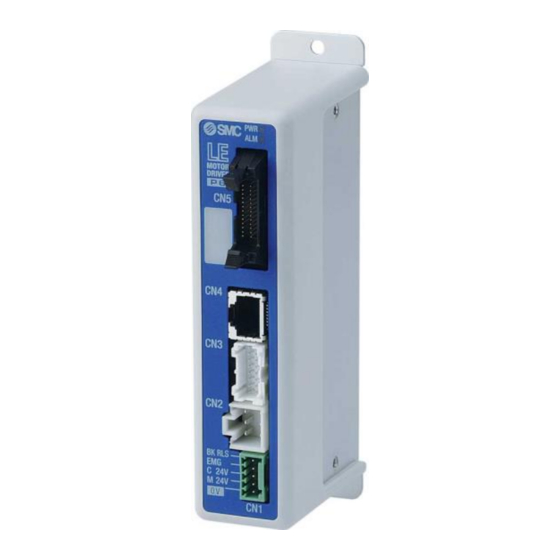
SMC Networks LECP6 Series Operation Manual
Data transfer procedure
Hide thumbs
Also See for LECP6 Series:
- Installation and maintenance manual (3 pages) ,
- Supplementary operation manual (28 pages) ,
- Operation manual (72 pages)
Table of Contents
Advertisement
Quick Links
Advertisement
Table of Contents

Summary of Contents for SMC Networks LECP6 Series
- Page 1 No. DOC1067059 PRODUCT NAME Data Transfer Procedure MODEL / Series LECP6/LECPMJ LECP6 JXC51/61 LECPMJ JXCM1 It will be necessary for the user to refer to the operation manual for the controller. (LECP6, LECPMJ, JXC51/ 61, JXCM1) and controller configuration software (ACT Controller).
-
Page 2: Table Of Contents
Contents 1. Safety Instructions ............2 2. Data Transfer Procedure ..........4 2.1 Outline ......................4 2.2 Transfer of the extended parameters .......... 4 3. Step1 How to store the LECP data ......5 3. 1 Preparation ....................5 3.2 How to store parameter files ............7 3. -
Page 3: Safety Instructions
Controller 1. Safety Instructions These safety instructions are intended to prevent hazardous situations and/or equipment damage. These instructions indicate the level of potential hazard with the labels of “Caution,” “Warning” or “Danger.” They are all important notes for safety and must be followed in addition to International Standards (ISO/IEC) , and other safety regulations. - Page 4 Controller 1.Safety Instructions Caution We develop, design, and manufacture our products to be used for automatic control equipment, and provide them for peaceful use in manufacturing business. Use in non-manufacturing business is not covered. Products we manufacture and sell cannot be used for the purpose of transactions or certification specified in the Measurement Act.
-
Page 5: 2. Data Transfer Procedure
2. Data Transfer Procedure 2.1 Outline This manual provides the data transfer procedure from LECP6 (hereafter named LECP) to JXC51/61 (hereafter named JXC) and from LECPMJ series to JXCM1 series. There are 2 types of data, Step data and Parameter data. The data can be stored on a PC using the controller configuration software (ACT Controller). -
Page 6: 3. Step1 How To Store The Lecp Data
3. Step1 How to store the LECP data 3. 1 Preparation The data can be stored using the controller configuration software (ACT Controller). Please refer to the Installation Manual for the controller configuration kit. Refer to the drawing below for the connection set up. Refer to the operation manual for the controller (LECP6 or LECPMJ) and the controller configuration software. - Page 7 Restart the controller configuration software after checking the points below. - The controller configuration software and the USB driver for the communication cable are installed in the computer. - The PC and controller are connected by using the communication cable for controller configuration. - The controller is supplied with power.
-
Page 8: 3.2 How To Store Parameter Files
3.2 How to store parameter files When the parameter window is not displayed, select “View(V)” from the menu bar in the Normal mode screen and select “Parameter”. Select “Upload All” in the parameter window (shown below) and read the parameter from the controller. Select “Save”... -
Page 9: Step Data Storage
3. 3 Step Data storage When the step data window is not displayed, select “View(V)” from the menu bar in the Normal mode screen and select “Step Data”. Select “Upload” from the step data window (shown below) and read the data from the controller. Select “Save”... -
Page 10: 4. Step2 Writing Parameter Data To The Jxc
4. Step2 Writing parameter data to the JXC 4. 1 Preparation The data can be stored using the controller configuration software (ACT Controller). Please refer to the Installation Manual for the controller configuration kit. Refer to the drawing below for the connection set up. Refer to the operation manual for the controller (JXC51/61 or JXCM1) and controller configuration software. -
Page 11: How To Store Parameter Files
4. 2 How to Store parameter files When the parameter window is not displayed, select “View(V)” from the menu bar in the Normal mode screen and select “Parameter”. Select "upload" from the parameter window (shown below) and read the saved parameter file which was stored from the controller. - Page 12 Select the “Download All” button to write the parameter protect to the controller. The PWR light of the controller (JXC51/61, JXCM1) flashes during writing. When the writing is complete, the PWR light will change from flashing to a steady light. Next, the step data is written.
-
Page 13: Step3 Writing Step Data To The Jxc
5. Step3 Writing step data to the JXC 5. 1 Writing Step Data This step follows “Step 2. Data Writing parameters to the JXC”. Before performing this step, check “4.1 Preparation”. When the step data window is not displayed, select “View(V)” from the menu bar in the Normal mode screen and select “Step Data”. -
Page 14: End
5. 2 The PWR light of the controller (JXC51/61, JXCM1) flashes during writing. When the writing is complete, the PWR light will change from flashing to a steady light. Close the controller configuration software and turn off the power to the controller. Then, disconnect the communication cable from the PC to the controller. - Page 15 Revision history 4-14-1, Sotokanda, Chiyoda-ku, Tokyo 101-0021 JAPAN Tel: + 81 3 5207 8249 Fax: +81 3 5298 5362 URL https://www.smcworld.com Note: Specifications are subject to change without prior notice and any obligation on the part of the manufacturer. © 2020 SMC Corporation All Rights Reserved - 14 -...


Need help?
Do you have a question about the LECP6 Series and is the answer not in the manual?
Questions and answers