Sign In
Upload
Manuals
Brands
SMC Networks Manuals
Controller
JXCM1
User Manuals: SMC Networks JXCM1 Step Motor Controller
Manuals and User Guides for SMC Networks JXCM1 Step Motor Controller. We have
3
SMC Networks JXCM1 Step Motor Controller manuals available for free PDF download: Operation Manual, Manual
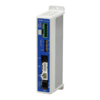
SMC Networks JXCM1 Operation Manual (120 pages)
CC-Link Direct Input Type Step Motor Controller (Servo 24 VDC)
Brand:
SMC Networks
| Category:
Controller
| Size: 4 MB
Table of Contents
Table of Contents
2
1 Safety Instructions
6
2 Outlines of Product
8
Features
8
Product Configuration
9
How to Order
10
1) Actuator Cable
11
2) Actuator Cable for Actuator with Lock (for Sensor and Lock)
12
Communication Connector
12
Communication Cable for Controller Setting
13
Power Supply Plug
13
Teaching Box
14
Start up Procedure
15
Checking the Contents of the Package
15
Mounting the Controller
15
Controller Setting
15
PLC Set up
15
Wiring and Connection
15
Power on Alarm (Error)
16
Setting Parameters
16
Setup of the Operation Parameters
17
Test Run
17
3 Specifications
18
Basic Specifications of the Product
18
CC-Link Communication
19
Parts Description
20
External Dimensions
21
Screw Mounting (JXCM17#-#)
21
DIN Rail Mounting (JXCM18#-#)
21
Mounting
22
Grounding
22
3) Mounting Location
23
Precautions for Electric Actuator Installation
24
4 Initial Setting
25
Switch (STATION NO., B RATE)
25
Parameter Setting
26
PLC Setting
27
5 External Connections
28
PWR: Power Supply Connector
28
MOT: Motor Connector, ENC: Encoder Connector
28
Serial I/O Connector
28
Connecting the Teaching Box
28
Connection with a PC
29
CC-Link Communication Connector
29
6 Details of Power Supply Plug
30
Power Supply Plug Specifications
30
Electrical Wiring Specifications
30
Power Supply Plug Wiring
31
Wiring of Power Supply (C24V, M24V, 0V)
31
Wiring of the Stop Switch (EMG)
31
Wiring of the Lock Release (LK RLS)
31
Wiring of Shutdown Circuit
32
Example Circuit 1- Single Controller with Teaching Box
32
Stop (Relay Contact (1))
33
Motor Power Shutdown (Relay Contact (2))
34
7 Communication Plug Connector
35
Wiring
35
Electric Wire Specification
36
Wiring of Communication Plug Connector
36
8 LED Display
37
LED and Controller Status
37
9 Mode
38
Outline
38
Step No. Instructions Operation Function
38
Position / Speed Monitor
39
Operation by Numerical Instruction
39
Data Editing Function
40
10 Memory Map
43
Remote IO (Rx and Ry)
43
Remote Register (Rwr and Rww)
49
11 Settings and Data Entry
60
Step Data
60
Basic Parameters
63
Return to Origin Parameter
66
Operation Parameters
67
12 Operations
68
Return to Origin Position
68
Positioning Operation
68
Pushing Operation
69
Pushing Operation Is Successfully Performed
69
Pushing Operation Fails (Empty Pushing)
69
Controller Input Signal Response Time
70
Methods of Interrupting Operation
70
13 Operation Examples
71
Positioning Operation
71
Pushing Operation
72
14 Start up Procedure for Battery-Less Absolute Encoder
73
Procedure for Start up
73
When Supplying Power for the First Time
74
Supply of Power
75
Alarm (Group E) Is Cleared by a Cut to the Power Supply
76
15 Operation Instructions
77
Operation Procedure for Operation by Step Date no
77
Power on and Return to Origin Position
77
Positioning Operation
78
Pushing Operation
78
Hold
79
Reset
79
Stop
79
Operation Procedure for Operation by Numerical Instruction
81
Operating Procedure for the Data Edit Function
82
16 Alarm for Motor Control
84
Output Signal of Remote IO for the Alarm Group
84
Alarms and Countermeasures
85
17 Alarm Detection for CC-Link Communication
92
Alarm Details
92
18 Precautions for Wiring and Cable
95
19 Electric Actuators/Common Precautions
96
Design and Selection
96
Mounting
97
Handling Precautions
98
Operating Environment
99
Maintenance Precautions
100
Precautions for Actuator with Lock
100
20 Controller and Peripheral Devices/Specific Product Precautions
101
Design and Selection
101
Handling Precautions
101
Mounting
102
Wiring
103
Power Supply
103
Grounding
103
Maintenance
104
Specific Precautions for Battery-Less Absolute Encoder
104
21 Troubleshooting
106
22 Memory Map List
112
23 Handling Remote Registers
116
Relationship of Bit Data, Byte Data, and Word Data
116
Relationship of Binary (BIN), Decimal (OCT), and Hexadecimal (HEX) Numbers
117
Installation
118
24 Definitions and Terminology
119
Advertisement
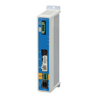
SMC Networks JXCM1 Manual (31 pages)
Step Motor Controller
Brand:
SMC Networks
| Category:
Controller
| Size: 8 MB
Table of Contents
Table of Contents
8
Controller (Step Data Input Type) JXC51/61
9
Series
9
How to Order
9
Specifications
9
How to Mount
10
Dimensions
11
Wiring Example
12
Step Data Setting
13
Jxc51/61
13
Signal Timing
14
Actuator Cable
15
Options: Actuator Cable
16
Options
17
Step Motor Controller JXCE1/91/P1/D1/L /M1
19
Series
19
How to Order
19
Specifi Cations
20
Example of Operation Command
20
Dimensions
21
Actuator Cable
24
Options: Actuator Cable
25
Options
26
Jxcl1
28
Precautions Relating to Differences in Controller Versions
28
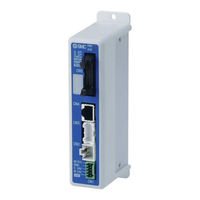
SMC Networks JXCM1 Operation Manual (15 pages)
Data Transfer Procedure
Brand:
SMC Networks
| Category:
Industrial Equipment
| Size: 0 MB
Table of Contents
Table of Contents
2
Safety Instructions
3
2. Data Transfer Procedure
5
2.1 Outline
5
2.2 Transfer of the Extended Parameters
5
3. Step1 How to Store the LECP Data
6
Preparation
6
3.2 How to Store Parameter Files
8
Step Data Storage
9
End
9
4. Step2 Writing Parameter Data to the JXC
10
Preparation
10
How to Store Parameter Files
11
Step3 Writing Step Data to the JXC
13
Writing Step Data
13
End
14
Data Transfer to a Blank Controller
14
Advertisement
Advertisement
Related Products
SMC Networks JXC73 Series
SMC JXC733
SMC JXC734
SMC JXC735
SMC JXC832
SMC JXC835
SMC JXC838
SMC Networks EtherNet/IP JXC91 Series
SMC Networks JXC6H
SMC Networks JXC-W2
SMC Networks Categories
Switch
Control Unit
Controller
Industrial Equipment
Network Router
More SMC Networks Manuals
Login
Sign In
OR
Sign in with Facebook
Sign in with Google
Upload manual
Upload from disk
Upload from URL