
Related Manuals for SMC Networks JXC73 Series


Summary of Contents for SMC Networks JXC73 Series
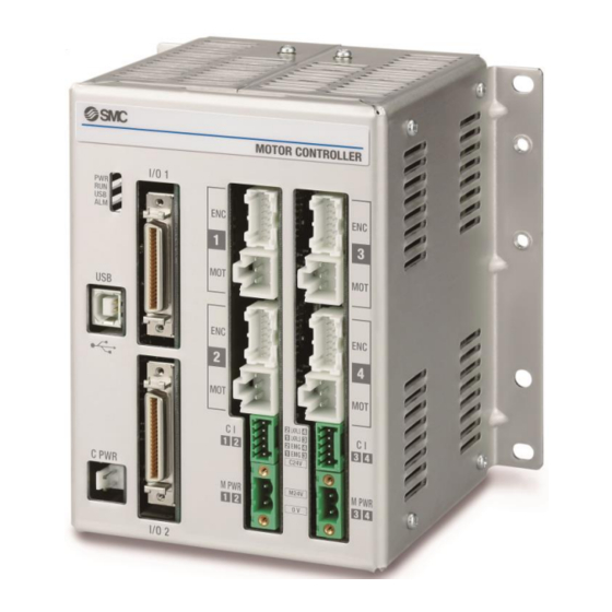
- Page 1 No.SFOD-OMT0010-B Product name 4-axis Step Motor Controller (Parallel I/O type) MODEL/ Series/ Product Number JXC73/83 Series...
-
Page 2: Table Of Contents
Contents 1. Safety Instructions ................ 5 2. Product Outline ................7 2.1 Features ......................7 2.2 How to Order ....................8 2.3 Product configuration ................9 3. Procedures to Trial run ............... 10 3.1 Checking the contents of the package .......... 10 3.2. - Page 3 (3) Mounting location ................30 5. Power supply connector ............. 31 5.1 Connector specifications ..............31 (1) Main control power supply connector: C PWR ....31 (2) Motor drive power connector: M PWR ........31 (3) Motor control power supply connector: CI ......32 5.2 Wiring .......................
- Page 4 8.8 Methods of interrupting operation ........... 73 9. Operation Instructions ..............74 9.1 Outline of the Operation instruction ..........74 9.2 Operation procedure of parallel I/O signals ........ 74 (1) From power on to Return to origin .......... 74 (2) Positioning operation ..............75 (3) Pushing operation ..................
- Page 5 14.5 Power supply ..................104 14.6 Grounding ....................104 14.7 Maintenance .................... 104 15. Troubleshooting ..............105 15.1 Operation Errors ................... 105 15.2 Position / Speed problems .............. 108 Supplement 1. Actuator Specifications ........110 Supplement 1.1 Initial setting of LEY/LEYG series ......... 110 Supplement 1.2 Initial setting of LEFS series ..........
-
Page 6: Safety Instructions
JXC73/83 Series / Controller 1. Safety Instructions These safety instructions are intended to prevent hazardous situations and/or equipment damage. These instructions indicate the level of potential hazard with the labels of “Caution,” “Warning” or “Danger.” They are all important notes for safety and must be followed in addition to International Standards (ISO/IEC) , and other safety regulations. - Page 7 JXC73/83 Series / Controller 1. Safety Instructions Caution 1.The product is provided for use in manufacturing industries. The product herein described is basically provided for peaceful use in manufacturing industries. If considering using the product in other industries, consult SMC beforehand and provide specifications or a contract, if necessary.
-
Page 8: Product Outline
2. Product Outline 2.1 Features This controller uses predefined "step data" in which multiple data such as position or speed are included together as operation instructions to the actuator. An external PLC specifies the step data number to the controller and will start the operation based on the step data. Feature of the controller. -
Page 9: How To Order
2.2 How to Order How to order is shown below. J X C 3 Electric equipment I/O cable or mounting Controller Note1) Symbol I/O cable Mounting Input/Output specifications 1.5m Direct mounting 1.5m DIN rail Direct mounting DIN rail 4 axis type Direct mounting DIN rail Direct mounting... -
Page 10: Product Configuration
2.3 Product configuration Structure of the controller. Note ● Electric actuator ● I/O cable Note2) Input/output Product No: JXC-C2- signal power supply 24VDC ●Controller Note To I/O ●Actuator cable Part No: To ENC LE-CP- Options (Robotic type cable) ... -
Page 11: Procedures To Trial Run
3. Procedures to Trial run Install, wire, set and perform a trial run for the controller referring to the procedure below when using the product for the first time. Check the contents of Mounting the controller Software Installation Wiring and connecting the package Supply power. -
Page 12: Mounting The Controller
3.2. Mounting the controller Refer to 4.4 Mounting for instructions on how to mount the controller. 3.3 Install the setting software and the driver Install the controller setting software and driver software on the PC to be used. For details, refer to the Installation Manual for the controller setting software (No.SFOD-OMT0008). 3.4 Wiring and connection Connect the cables to the controller. -
Page 13: Start-Up Of Controller Setting Software
(2) Start-up of controller setting software Using a PC with the controller setting software installed, start the application “SMC / JXC Controller” to start the setting software. If the controller setting software is installed with the default setting, an icon will be created on the desk top. -
Page 14: Alarm Check
After the initial title window is displayed, the following main window will be displayed. The communication status between the controller and PC is indicated at the bottom of the main window. Display Details Off-line state On-line state When the PC is able to communicate with the controller, "On-line" status is established automatically. -
Page 15: Parameters And Step Data
3.6 Parameters and Step data When using for the first time or after changing the connected actuator, or when the settings of the controller or connected actuator have been changed, it is necessary to review the set parameters and step data. It is possible to display parameters and step data as shown below. - Page 16 Input the partnumber of the actuator to be used in the “Search from Part No. area”. A list of part numbers of the actuators matching the conditions will be displayed by clicking the "Result" button. Select the actuator to be connected. Result Search from Part No.
- Page 17 Select the check box for the axis for which parameters are to be input (one or more boxes are possible to be selected). Select the "Execute" button. Axis parameters will be displayed in the Actuator selection window. The values input here are for display only, and are not written to the controller.
-
Page 18: Setting Parameters
(2) Setting parameters Set the parameters such as for valid axis and electronic gear. Check the parameters below and change them if necessary. For other items, refer to section 7. Settings and Data Entry. Parameter name Input range Outline Max step Maximum step data. - Page 19 After setting parameters, select the "Download" button in the parameter window. Parameters in the parameter window will be written to the controller. Writing is completed when the progress bar disappears and then the setting software is ready to operate. It is necessary to turn off the power to the controller and turn it on again. The downloaded parameters will become valid after turning the power on again.
-
Page 20: Step Data Settings
(3) Step data settings Select "View(V)" at the top of the main window, and select "Step Data". The Step data window will be displayed. Download Movement mode Area to input numerical data. Select the “▼” button for the movement mode for the axis of the step number to be set. Select the movement mode shown in the list. -
Page 21: Check Using Jog Operation
3.7 Check using JOG operation (1) Change to Remote mode Change the mode to Remote mode at the top of the main window. The Servo will be turned on by selecting Remote mode. Confirm that the Servo is ON. (Confirm SVRE ON in the status window.) Select "View(V)"... -
Page 22: Return To Origin
(2) Return to origin Select "View(V)" at the top of the main window, and select "Teaching". The teaching window will be displayed. Return to Origin tab All axes Return to Origin Select the “Return to Origin” tab. Select “Return to Origin(●)” or “All axes Return to Origin”. When the return to origin setting is completed, SETON is ON. -
Page 23: Jog Or Inching
(3) JOG or Inching Select the “JOG” or “Inching” tab. JOG tab Inching tab Speed Travel distance +/- button (a) JOG Set the "Speed". The Position will move in the "+" or "-" direction as long as the "+" or "-" button is pressed. -
Page 24: Operation Test Using Test Drive
3.8 Operation test using Test Drive Select "View(V)" at the top of the main window, and select "Test Drive". The Test Drive window will be displayed. It is possible to test the set step data in a specified order. (1) Test Drive setting Set the order of the step data number for testing in the test drive list window. -
Page 25: Return To Origin
(3) Return to origin Confirm that SVRE output is ON, refer to section 3.7 (1) Change to Remote mode. Then, select "All axes Return to Origin", and perform the “Return to origin” operation. (4) Test drive starts Confirm that SETON output is ON, refer to section 3.7 (2) Return to origin. Test drive starts by pressing the "Go"... -
Page 26: Product Specifications
4. Product Specifications 4.1 Basic Specifications Basic specifications of the product. Item Specifications Number of axes per Max. 4 axis controller Controlled motor Step motor (servo 24 VDC ) Controlled encoder Incremental phase A / B (Encoder resolution 800 pulse / rotation) Main control power supply Power supply voltage: 24VDC+/-10% Power supply... -
Page 27: Parts Description
4.2 Parts Description Detail of the controller parts. (10) (15) (16) (11) (12) (17) (18) (19) (20) (13) (14) Display Description Details Power supply LED (green) Power supply ON: LED is ON Power supply OFF: LED is OFF Operation by parallel I/O: LED is ON Operating LED (green) Operation by USB communication: LED is Flashing Stop: LED is OFF... -
Page 28: Dimensions
4.3 Dimensions (1) Direct mounting (2) DIN rail mounting - 27 - No.SFOD-OMT0010-B... -
Page 29: Mounting
4.4 Mounting (1) Mounting There are two ways to mount the controller. (Direct mounting with screws and DIN rail mounting) Controller mounting methods are shown below. (a) Direct Mounting with four M5 screws Mounting screw (M5) 4pcs. (prepared by customer) (b) DIN rail mounting The figure on the right shows how to mount the DIN rail mounting brackets. -
Page 30: Grounding
The figure below shows how to mount the controller to the DIN rail. Hook part A on to the DIN rail. Press part B on to the DIN rail and tighten the holding screws (M5 x 14). (Appropriate tightening torque: 0.4 to 0.6Nm) Part A Part B Holding screw... -
Page 31: Mounting Location
Caution (1) A dedicated ground connection must be used. Grounding should be to a D-class ground (ground resistance of 100Ω or less). (2) The cross sectional area of the grounding cable should be 2mm minimum. The grounding point should be as near as possible to the controller, to keep the grounding cable as short as possible. -
Page 32: Power Supply Connector
5. Power supply connector 5.1 Connector specifications The power supply connector type included is shown below. (1) Main control power supply connector: C PWR Brown Terminal Function Description +24V +24V Main control power supply (+) Power supply (+) for main control. 24-0V 24-0V Main control power supply (-) -
Page 33: Motor Control Power Supply Connector: Ci
(3) Motor control power supply connector: CI Terminal Function Functional explanation Motor control power C24V Power supply side (+) for motor control. supply (+) Release the stop status (+) of Axis 1 or Axis 3. EMG1/EMG3 Stop(+) (Normal operation by applying 24V.) Release the stop status (+) of Axis 2 or Axis 4. -
Page 34: Wiring
5.2 Wiring Connect the main control power supply, motor drive and motor control power supply while referring to (1) to (3) below, and then insert into the controller C PWR, Cl and M PWR. (1) Wiring of the power supply connector Connect the main control power supply 24V and 0V to the main control power supply connector +24V and 24-0V terminals. -
Page 35: Wiring Of The Stop Switch
(2) Wiring of the stop switch A Stop switch must be installed by the user to stop the actuator in abnormal situations. The actuator stops its operation when the external shutdown switch is activated. - Stop (Stop switch) To stop the controller, connect the stop switch (B contact) between the motor drive and motor control power supply and the EMG terminal of the motor control power supply connector. - Page 36 Motor power shutdown (relay contact) If it is necessary to have a circuit to shutdown the motor drive power externally, relay contacts should be placed between the motor drive and motor control power supply and the M24V of the motor control power supply connector and the EMG terminal of the motor control power supply connector.
-
Page 37: Details Of Parallel I/O Connector
6. Details of parallel I/O connector This controller is available with NPN type (JXC73 ) or PNP type (JXC83 ) parallel I/O. 6.1 Parallel I/O specifications ■Input specifications ■Output specifications (NPN) (NPN) Item Specifications Item Specifications Internal circuit and Optically Internal circuit Input circuit... -
Page 38: Parallel I/O Output Circuit
(2)Parallel I/O output circuit -NPN type I/O 1 Inside the controller External +COM1, +COM2 OUT0 to OUT8, BUSY, AREA, SETON, INP, SVRE, ESTOP, 10KΩ ALARM -COM1, -COM2 I/O 2 20KΩ +COM3, +COM4 BUSY1 to BUSY4, AREA1 to AREA4, INP1 to INP4, ALARM1 to ALARM4 -COM3, -COM4 -PNP type... -
Page 39: Parallel I/O Signals
6.3 Parallel I/O signals Pin No. Pin No. Insulator colour Dot mark Dot colour Insulator colour Dot mark Dot colour Orange ■ Orange ■■■ Black Black Orange ■ Orange ■■■ Grey ■ Grey ■■■ Black Black Grey ■ Grey ■■■ White ■... -
Page 40: I/O1
(1) I/O1 -Input side Signal Pin No. Description name Connect the 24 VDC power supply to the input/ output signals +COM1 For IN0 to IN10, SETUP, HOLD, DRIVE, RESET, SVON +COM2 For OUT0 to OUT8, BUSY, AREA, SETON, INP, SVRE, ESTOP, ALARM Step data instruction Bit No.(Standard: When 512 is used) Step data instruction Bit No. - Page 41 Signal Pin No. Description name Alarm reset and interruption of operation When RESET is turned ON during operation, the speed decreases at maximum deceleration of the basic parameter until the actuator stops. INP and OUT0 to OUT10 are OFF. (However, if the actuator is stopped within the in-position range, the INP will be turned ON).
- Page 42 -Output side Signal Pin No. Description name OUT0 OUT1 Output the number of ongoing step data. When the operation is started and the DRIVE input is turned ON, a Bit No. corresponding OUT2 to the number of the active step data will be output from these terminals. These output OUT3 signals will be updated when the DRIVE input is turned ON.
-
Page 43: I/O2
(2) I/O2 -Input side Pin No. Signal name Description Connects the power supply 24 V to the input/output signals +COM3 For BUSY1 to BUSY4, AREA1 to AREA4, INP1 to INP4, and ALARM1 to +COM4 ALARM4. Unused N.C. -Output side Pin No. Signal name Description BUSY1... - Page 44 The table below shows the changes in the output signal with respect to the state of the controller. Output BUSY SVRE Lock SETON OUT0 to 8 Status signal Controller powered down [SVOFF] with no Lock motion Controller powered down [SVON] with no Note1) Unlock motion...
-
Page 45: Parallel I/O Wiring Example
6.4 Parallel I/O Wiring Example The Wiring depends on the parallel input/output type of the controller (NPN or PNP). Caution Prepare a separate power supply for the main control, motor drive and motor control and input/ output signal. (1) NPN type I/O 1 24 VDC OUT0... - Page 46 I/O 2 24 VDC BUSY1 Load +COM3 BUSY2 Load +COM4 BUSY3 Load Note 1) N.C. BUSY4 Load Note 1) N.C. AREA1 Load Note 1) N.C. AREA2 Load Note 1) AREA3 N.C. Load AREA4 Note 1) N.C. Load INP1 Load Note 1) N.C.
-
Page 47: Pnp Type
(2) PNP type I/O 1 24 VDC OUT0 Load +COM1 OUT1 Load +COM2 OUT2 Load OUT3 Load OUT4 Load OUT5 Load OUT6 Load OUT7 Load OUT8 Load BUSY Load (OUT9) AREA Load (OUT10) SETON Load Load IN10 SVRE Load SETUP ESTOP Load ALARM... - Page 48 I/O 2 24 VDC BUSY1 Load +COM3 BUSY2 Load +COM4 BUSY3 Load Note 1) N.C. BUSY4 Load Note 1) N.C. AREA1 Load Note 1) N.C. AREA2 Load AREA3 Note 1) N.C. Load AREA4 Note 1) Load N.C. INP1 Load Note 1) N.C.
-
Page 49: Setting Data Entry
7. Setting Data Entry In order to move the actuator to a specific position, it is necessary to program the parameters and step data in the controller using a PC with the controller setting software installed. The data entered using the controller setting software will be stored in the memory of the controller. 7.1 Profile parameter The “Profile parameter”... -
Page 50: Basic Parameter
7.2 Basic parameter The “Basic parameter” is the data to define the operating conditions of the controller, conditions of the actuator, etc. Activation: “XX” = Become effective just after storing in the controller “X” = Become effective after restarting the controller “-“... - Page 51 Description Input range Explanation Write Define the electronic Gear. - Undefined No.11: "Electronic Gear (numerator)" - Undefined No.12: "Electronic Gear (denominator)" This product controls the LE series motor (800 pulse per rotation). Please refer to Supplement 1. Actuator Specifications for the travel distance of the motor per rotation.
-
Page 52: Return To Origin Parameter
7.3 Return to origin parameter The “Return to origin parameter” is the setting data for the return to origin operation. Activation: “XX” = Become effective just after storing in the controller “X” = Become effective after restarting the controller “-“ = The parameter cannot be changed (fixed value). Input Description Explanation... -
Page 53: Step Data
7.4 Step data A “step data” is the data set to define the movement of the actuator. Total of 512 step data (9 attributes per step) are possible to be handled by this controller. (When "2048" is set for "Max step data Num"... - Page 54 Description Input range Explanation “Stroke (-)” to “Stroke Set the target position (unit: mm) (+)” in the basic Position Refer to (1) to (5) on page 54 for position setting for movement mode. parameters Set the acceleration to reach to travel speed. (Unit mm/s 1 to “Max ACC/DEC”...
-
Page 55: Abs
Different settings for each movement mode are shown below. (1) ABS Step Movement Speed Position Acceleration Deceleration Pushing Area 1 Area 2 In-position Axis mode (mm/s) (mm) (mm/s (mm/s Selection (mm) (mm) (mm) 200.00 1000 1000 12.0 Axis 1 100.00 1000 1000 12.0... -
Page 56: Cir-R / Cir-L
(4) CIR-R / CIR-L Step Movement Speed Position Acceleration Deceleration Pushing Area 1 Area 2 In-position Axis mode (mm/s) (mm) (mm/s (mm/s Selection (mm) (mm) (mm) CIR-R 100.00 1000 1000 Axis 1 CIR-R 100.00 Axis 2 Note1) 50.00 Axis 3 Note1) 50.00 Axis 4... -
Page 57: Description Of Operation
8. Description of operation 8.1 Return to origin After entering the step data, it is necessary to perform a return to origin operation before positioning the actuator. (To ensure the position of origin) The actuator moves in the Return to origin direction (*dependent on the actuator) from the initial position at the moment of power-on. -
Page 58: Positioning Operation
8.2 Positioning Operation When the "Pushing selection" step data is "0" for a Positioning operation. The actuator moves to the target position specified by the step data “Position.” ● ● Positioning Operation (Example) Positioning operation [Speed/Position] (Example) Step Data Speed "In-position"... - Page 59 Operation (Example) Actuator Load Load Actuator Motor Motor Axis 1 Axis 2 50mm 60mm 100mm 50mm 60mm 100mm Origin position End position Origin position End position Actuator Load Load Actuator Motor Motor Axis 3 Axis 4 50mm 60mm 100mm 50mm 60mm 100mm Origin position End position...
- Page 60 Flow chart (Reference) (1) Select input Step No.1. (Turn IN0 ON.) ↓ (2) Turn the "DRIVE" input ON. Controller ↓ Parallel I/O signals The Motor starts to move to the position set in Step No.1. ↓ (3) Step No.1 output turns on. Signal name Category (OUT0 output is turned ON)
-
Page 61: Pushing Operation
8.3 Pushing Operation When the "Pushing selection" step data is "1", for a pushing operation. First a positioning operation is performed to the "Target" position andaccording to the "Speed"set in the step data. The pushing operation starts from this"Position" for a maximum distance defined by the "Positioning width". - Page 62 (3) Movement of the workpiece after completingthe pushing operation (a) The workpiece moves in the pushing direction. After completing the pushing operation, if the reaction force from the workpiece becomes smaller, the actuator may move with a force smaller than that specified in the “Trigger level” of the profile parameter.
- Page 63 Example) After a Return to origin, move 4 axes from the origin to 100mm position at 100mm/s. From 100mm position, pushing maximum speed 10mm/s(profileparameter: Pushing speed) at 50% or lower of thrust(profile parameter: Pushing force) (Step No.1). Then, move 4 axes to 50 mm position from the origin at 50mm/s from the Pushing completed position (position where "INP"...
- Page 64 Flow chart (Reference) (1)Select input Step No.1. (Turn IN0 ON.) ↓ (2)Turn the "DRIVE" input ON. ↓ The Motor starts to move to the position set in Step No.1. ↓ (3) Step No.1 output is turned ON. (OUT0 output is turned ON) Controller ↓...
-
Page 65: Linear Interpolation
8.4 Linear interpolation Move axes in a straight line from the current position at a defined "Speed" (composite speed for the speed of each axis) to a "Position" set in the step data.The speed of each axis is calculated using the formulae below. - Page 66 Example) After a Return to origin, move from the origin position at 100mm/s of composite speed to a point at100mm on Axis 1 and 100mm on Axis 2 (Step No.1). Then, move from the current position at 50mm/s of composite speed to a point at 100mm on Axis 1 and 50mm on Axis 2 (Step No.2).
- Page 67 Flow chart (Reference) (1) Select input Step No.1. (Turn IN0 ON.) ↓ (2) Turn the DRIVE input ON. Controller ↓ The Motor starts to move to the position set in Step No.1. Parallel I/O signals ↓ (3)Step No.1 output is turned ON. Signal name Category (OUT0 output is turned ON)
-
Page 68: Circular Interpolation
8.5 Circular interpolation Circular interpolation by specifying the target coordinate (relative) and centre coordinate (relative) referring to Axis 1 as the X axis and Axis 2 as the Y axis. Clockwise circular interpolation is in CIR-R mode and counterclockwise is in CIR-L mode. Each axis travels at a speed lower than the composite speed. - Page 69 Caution Setting of the electronic Gear is necessary when actuators with different a lead are used. If the electronic gear is not set, the step data operation may not be produced. Refer to section 3.6 Parameters and Step data for the calculation of the electronic Gear. Caution When mode CIR-R/L is repeatedly used, there will be an accumulated error in the achieved position due to the motor resolution.
- Page 70 Example) After a Return to origin, move from the origin position at 100 mm/s to a point 30mm on Axis 1 and 10mm on Axis 2 (Step No.1). Move from the current position using counterclockwise circular interpolation movement at 100 mm/s composite speed to a point 0mm on Axis 1 and 40mm on Axis 2 (Step No.2: Centre position 0mm on Axis 1, 20mm on Axis 2).
- Page 71 Flow chart (Reference) (1)Select input Step No.1. (Turn IN0 ON.) ↓ (2)Turn the DRIVE input ON. Controller ↓ The Motor starts to move to the position set in Step No.1. Parallel I/O signals ↓ (3) Step No.1 output is turned ON. Signal name Category (OUT0 output is turned ON)
-
Page 72: Speed Tuning Control
8.6 Speed tuning control When an (main) axis is delayed due to external load, the speed of other (slave) axes is controlled. Not the synchronization of the position of the main axis and slave axis. Pushing operation cannot be used. Caution (1) Actuators with a different lead cannot be used. - Page 73 Example) After a Return to origin, move all axes synchronously from the origin to 200mm position at 100mm/s. (Step Data No.0 is used for this operation). Step Data Setting Example Pushing Step Movement Speed Position Acceleration Deceleration Area 1 Area 2 In-position Axis Selection...
-
Page 74: Controller Input Signal Response Time
8.7 Controller input signal response time The controller input signal response time includes the following factors. 1) Controller input signal scan time 2) Delay due to input signal analysis 3) Delay due to command analysis Leave an interval of 15ms or more (recommendation is 30 ms) between input signals and maintain the state of the signal for 15ms or more (recommendation is 30 ms), because PLC processing delays and controller scanning delays could occur. -
Page 75: Operation Instructions
9. Operation Instructions 9.1 Outline of the Operation instruction The actuator is operated by selecting step data which is preset in the controller, using parallel I/O signals. Refer to the following section for details of the parallel I/O signal timing and control procedures. -
Page 76: Positioning Operation
(2) Positioning operation - Procedure - - Timing chart - (a) Input the step data No.(INx). Power supply ↓ (b)Turn the DRIVE input ON. Min.15ms The step data No. (OUT x output) will be output. Previous step No. ↓ Current step No. OUTx (c) The BUSY output turns ON and INP output turns OFF. -
Page 77: Pushing Operation
(3) Pushing operation - Procedure - - Timing chart - (a) Input the step data No. Power supply (INx). ↓ Min.15ms (b) Turn the DRIVE input ON. The step data No. Previous step data No. (OUTx output) will be Current step data No. output. -
Page 78: Hold
(4) HOLD - Procedure - - Timing chart - (a) The HOLD input is turned ON during a movement operation (when the BUSY output is ON). ↓ (b) The BUSY output turns OFF. Previous step data No. (The actuator will stop). ↓... - Page 79 [Reset of operation] - Procedure - - Timing chart - (a) The RESET input is turned ON during a movement operation (when the BUSY output is ON). ↓ Current step data No. (b) The BUSY output is OFF and Previous step data No. OUTx output is OFF.
-
Page 80: Stop
(6) STOP - Procedure - Timing charge - (a) The Stop (EMG) input is OFF during an operation (when the BUSY output is ON). (Stop command) ↓ (b) The ESTOP output will turn OFF. ↓ (c) The BUSY output will turn OFF. (The actuator will stop). -
Page 81: Area Output
(7) Area output -Procedures- (a) Input the Step data No. (INx). (b) Turn the "DRIVE" input ON. Step data No. 1 (OUTx output) will be output. (c) The BUSY output will turn ON and INP output will turn OFF (the positioning operation will starts). (d) The AREA output of step data No.1 turns ON (at 150mm from the origin point). -
Page 82: Accessories
10. Accessories Power cable for main control 10.1 JXC-C1 (1500) Cable colour: Blue (0V) Cable colour: Brown(24V) Cable specification Item Specifications Cable length 1.5m Stranded wire --> AWG20 (0.5mm Electric wire size O.D. of sheath →1.76 mm +24V: Brown Wire sheath colour 24-0V: Blue 10.2 DIN rail mounting bracket JXC-Z1... -
Page 83: Actuator Cable (5M Or Less)
10.3 Actuator cable (5m or less) L E - C P - - Terminal Signal name Terminal number Cable colour number Brown Cable length [L] Orange 1.5m Yellow Green COM-A/COM Blue COM-B/ - Terminal Shield Cable colour number Brown Cable type Black Robotic type cable... -
Page 84: Actuator Cable [For Sensor/ With Lock (5M Or Less)]
10.5 Actuator cable [For sensor/ with lock (5m or less)] Signal name Terminal L E - C P - - B - Cable color Terminal number number Brown Cable length [L] Orange Yellow 1.5m COM-A/COM Green COM-B/ - Blue Shield Cable color... -
Page 85: Paralleli/O Cable
10.7 ParallelI/O cable J X C - C 2 - Cable length [L] 1.5m Core number AWG size AWG28 PLC side Controller side Ground cable (green), round terminal R1.25-4 (For M4 screw) The separate lines of the terminal on the PLC side are fusion together with an adhesive tape with a pitch of 1.27mm. -
Page 86: Controller Set Up Kit
10.8 Controller Set up kit JXC-W1 Contents (1) Controller set up software (CD-ROM) Product No.: JXC-W1-1 (2) USBcable (A-B type) Product number JXC-W1-2 Controller Operating environment Compatible OS Windows®7 (32bit or 64bit) Microsoft .NET Framework 2.0 is necessary. Note1) Windows®8.1 (32bit or 64bit) Microsoft .NET Framework 3.5 is necessary. Hard disk 50MB or more space... -
Page 87: Alarm Detection
11. Alarm detection The details of an alarm generated are possible to check using a PC (with controller setting software). Please refer to the controller setting software manual (No. SFOD-OMT0012) to check the details of the alarms. When an alarm is generated, deactivate the alarm after troubleshooting and correcting the error with reference to section 11.2 Alarms and countermeasures. -
Page 88: Alarms And Countermeasures
11.2 Alarms and countermeasures (1) Controller alarm Name of controller How to Alarms and countermeasures setting deactivate software (code) < Details > An alarm is generated when the Drive operation [DRIVE] is DRIVE is ON when ON when the servo [SVRE] is OFF after a Return to origin. Input SVRE is RESET... - Page 89 Name of controller How to Alarms and countermeasures setting deactivate software (code) < Details > Turn off Abnormality concerning FROM is confirmed. the main FROM control <Countermeasure> Error and motor Please contact SMC. (0-912) control power supplies. < Details > Turn off An alarm is generated when an abnormality is found in the the main...
- Page 90 (2) Driver alarm Name of controller How to Alarms and countermeasures setting deactivate software (code) < Details > The step data or parameter is incorrect for the following parameter assignable range. [Settable range] (1) Pushing force ≥ Trigger level (2) Pushing force > 0 (3) Speed ≥...
- Page 91 Name of controller How to Alarms and countermeasures setting deactivate software (code) < Details > Return to origin was not completed within the set time. <Countermeasure> Return to - If the ORIG mode is "0: Pushing Return to origin", the controller ORIG did parameter “model”...
- Page 92 Name of controller How to Alarms and countermeasures setting deactivate software (code) < Details > The origin sensor does not respond correctly when a Return to origin operation is performed with the origin sensor. An Alarm is generated depending on the set value of the Return to origin parameter.
- Page 93 Name of controller How to Alarms and countermeasures setting deactivate software (code) < Details > The motor speed has exceeded the specified value, possibly due to an external force, etc. Speed <Countermeasure> Input exceeded Make improvements to ensure that the motor speed will not RESET set value exceed the maximum speed of the actuator.
- Page 94 Name of controller How to Alarms and countermeasures setting deactivate software (code) < Details > The power supply voltage for motor control detected by the controller is outside of the specified range. <Countermeasure> Check the motor control power supply voltage connected to the controller.
- Page 95 Name of controller How to Alarms and countermeasures setting deactivate software (code) < Details > Turn off the An abnormality occurred in communication with the main control encoder. Encoder and motor error control (1-192) <Countermeasure> power Check the actuator cable connection. supplies.
-
Page 96: Common Precautions For Wiring And Cable
12. Common Precautions for wiring and cable Warning 1. Adjustment, mounting, inspection or wiring should never be carried out before disconnecting the power supply to the product. Electric shock, malfunction and damage can result. 2. Do not disassemble the cable. Use only specified cables. 3. -
Page 97: Electric Actuators / Common Precautions
11. The Speed/ pushing force may vary, depending on the cable length, load and mounting conditions etc. If the cable length exceeds 5m, the speed/ pushing force will decrease by a maximum of 10% per 5m. (If cable length is 15m: Maximum 20% reduction.) [Transport] Caution 1. -
Page 98: Mounting
Caution Use the product for the maximum usable stroke. The product will be damaged if it is used with a stroke exceeding the maximum stroke. Refer to the specifications of the product. When the product repeatedly cycles with partial strokes, operate it at a full stroke at least once a day or every 1,000 strokes. -
Page 99: Handling Precautions
8. Cantilever When the actuator is operated at high speeds while it is fixed at one end and free at the other end (flange type, foot type, double clevis type, direct mount type), a bending moment may act on the actuator due to vibration generated at the stroke end, which can damage the actuator. -
Page 100: Operating Environment
4. Actual speed of the product will be changed by the workload. Before selecting a product, check the catalog for the instructions regarding selection and specifications. 5. Do not apply a load, impact or resistance, in addition to a transferred load during the “Return to Origin”... -
Page 101: Maintenance And Precautions
[Storage] Warning Do not store the product with direct contact to rain or water drops. Do not store the product where it is exposed to harmful gases or liquid. Store in an area that is shaded from direct sunlight and has a temperature and humidity within the specified range (-10 C to 60 C and 35 to 85%. -
Page 102: Controller And Peripheral Devices / Specific Product Precautions
4. Do not apply an impact load or strong vibration while the lock is activated. If an external impact load or strong vibration is applied to the product, the lock will lose its holding force and damage to the sliding part of the lock or reduced lifetime can result. The same situations will happen when the lock slips due to a force over the thrust of the product, as this accelerates the wear to the lock. - Page 103 3. A product that is damaged or missing any components should not be used. Electric shock, fire, and injury can result. 4. For the controller, set parameters which are appropriate to the connected actuators. Operation with inappropriate parameters may cause failure of the controller or actuator, or damage to the user's systems.
-
Page 104: Mounting
14.3 Mounting Warning 1. The controller and its peripheral devices should be installed on a fire-proof material. Direct installation on or near a flammable material may cause fire. 2. Do not install this product in a location subject to vibration and impact. A failure and malfunction can result. -
Page 105: Power Supply
14.5 Power supply Caution 1. Use a power supply with low noise between lines and between power and ground. In cases where noise is high, use an isolation transformer. 2. The power supplies for the controller power and the I/O signal power should be separate, and both Power supplies should not be of the “in-rush current limiting type”. -
Page 106: Troubleshooting
15. Troubleshooting Refer to the table below for troubleshooting. When none of the causes in the troubleshooting are possible to be confirmed, it is presumed that the product is faulty and normal operation could only be recovered by the replacement of a part. It is possible that this product may be damaged due to the operating conditions (applications). - Page 107 Possible Problems Investigation method Countermeasures causes Check if the controller has generated an Refer to thismanual and take appropriate Alarm alarm? Check the type of alarm, referring measures. generated to this manual. -> 11. Alarm detection Correct the wiring so that the input/output of each signal is performed appropriately.
- Page 108 Possible Problem Investigation method Countermeasures causes The USB Install the USB driver for the USB cable. driver is Check that the USB driver for the USB Details of the installation procedure are cable is installed. given in the controller setting software installed Installation Manual.
-
Page 109: Position / Speed Problems
15.2 Position / Speed problems Possible Problems Investigation method Countermeasures causes For a pushing operation, repeat the Return Incorrect to origin operation several times to check Check the actuator operation (if foreign matter origin that the actuator returns to the origin is caught in the product etc.). - Page 110 Possible Problems Investigation method Countermeasures causes Check that the parameter values are correct. Correct the parameter values and test the Incorrect Review the maximum speed and the operation. parameters maximum acceleration and deceleration of -> 7. Settings Data Entry the actuator. Check if a triangular acceleration / deceleration is programmed for the Operation...
-
Page 111: Supplement 1. Actuator Specifications
Supplement 1. Actuator Specifications Supplement 1.1 Initial setting of LEY/LEYG series Model LEY16/LEYG16 LEY25/LEYG25 LEY32/LEYG32 LEY40/LEYG40 Lead symbol Lead [mm] Stroke [mm] Max. speed [mm/s] Min. speed [mm/s] (Independent interpolation) Min. speed [mm/s] (Speed tuning control) Supplement 1.2 Initial setting of LEFS series Model LEFS16 LEFS25... -
Page 112: Supplement 1.3 Initial Setting Of Les(H) Series
Model LEFS40 Lead symbol Lead [mm] Stroke [mm] 1200 1000 1100 1200 1000 1100 1200 Max. speed [mm/s] Min. speed [mm/s] (Independent and interpolation) Min. speed [mm/s] (Speed tuning control) Supplement 1.3 Initial setting of LES(H) series Model LES(H)8 LES(H)16 LES(H)25 Lead symbol Lead [mm]... -
Page 113: Supplement 1.5 Initial Setting Of Lefb Series
Supplement 1.5 Initial setting of LEFB series Model LEFB16 LEFB25 LEFB32 Lead symbol Lead [mm] Max. speed [mm/s] 1100 1400 1500 Min. speed [mm/s] (Independent and interpolation) Min. speed [mm/s] (Speed tuning control) Supplement 1.6 Initial setting of LER series Model LER10 LER30... - Page 114 Model LEHF10 LEHF20 LEHF32 LEHF40 Lead symbol Lead [mm] 40/15 50/15 70/16 70/16 (2.667) (3.333) (4.375) (4.375) Max. speed [mm/s] Min. speed [mm/s] (Independent and interpolation) Min. speed [mm/s] (Speed tuning control) Model LEHS10 LEHS20 LEHS32 LEHS40 Lead symbol Lead [mm] 255/76 235/56 235/40...
- Page 115 Revision history No. SFOD-OMT0010 First edition: September 2015 No. SFOD-OMT0010-A Contents revised in several places: March 2016 No. SFOD-OMT0010-B Revised 10.6 Speed tuning control :Feb 2019 (Rivised Synchronous to speed tuning control) 4-14-1, Sotokanda, Chiyoda-ku, Tokyo 101-0021 JAPAN Tel: + 81 3 5207 8249 Fax: +81 3 5298 5362 http://www.smcworld.com Note: Specifications are subject to change without prior notice and any obligation on the part of the manufacturer.
Need help?
Do you have a question about the JXC73 Series and is the answer not in the manual?
Questions and answers