
Related Manuals for SMC Networks JXCE1


Summary of Contents for SMC Networks JXCE1
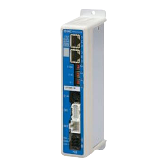
- Page 1 No.JXC※-OMU0008-E PRODUCT NAME EtherCAT Direct input type Step Motor Controller (Servo 24VDC) Model / Series / Product Number JXCE1...
-
Page 2: Table Of Contents
Table of Contents 1. Safety Instructions ..........4 2. Outlines of Product ..........6 2.1 Features ..................6 2.2 How to Order................7 2.3 Product configuration ............... 8 2.4 Start up procedure ..............9 (1) Checking the contents of the package ......9 (2) Mounting the controller ............. - Page 3 (1)Stop (example of recommended circuit) ......23 (2) Stop (relay contact (1)) ............ 24 (3) Motor power shutdown (relay contact (2)) ....25 7. LED display ............26 7.1 LED display ................26 7.2 LED and Controller Status ............. 26 8.
- Page 4 14. Options ............. 54 14.1 Actuator cable [5m or shorter] ..........54 14.2 Actuator cable [8 to 20m] ............. 54 14.3 Actuator cable for with lock [5m or less] ......55 14.4 Actuator cable for with lock [8 to 20m] ....... 55 14.5 Controller Communication Cable ........
-
Page 5: Safety Instructions
JXCE1/Controller 1. Safety Instructions These safety instructions are intended to prevent hazardous situations and/or equipment damage. These instructions indicate the level of potential hazard with the labels of "Caution", "Warning" or "Danger". They are all important notes for safety and must be followed in addition to International 1) - Page 6 JXCE1/Controller 1. Safety Instructions Caution The product is provided for use in manufacturing industries. The product herein described is basically provided for peaceful use in manufacturing industries. If considering using the product in other industries, consult SMC beforehand and provide specifications or a contract, if necessary.
-
Page 7: Outlines Of Product
2. Outlines of Product 2.1 Features Features of the controller. ●EtherCAT compatible This device can be directly connected to a EtherCAT fieldbus network. It will then be possible to establish communication with a EtherCAT Master (PLC). ●Actuator control Positioning operation and operation at a specific speed and force for the actuator are possible by controlling the Step motor (servo 24VDC). -
Page 8: How To Order
2.2 How to Order How to order is shown below. JX C E 1 Electric equipment Controller Actuator Model (Enter from the actuator model to "stroke") Controller type E.g.) LEFS16B-100B-S1CE17, EtherCAT input “LEFS16B-100”. Number of shaft/ Mounting Type of power supply Direct mounting 1 axis, Power supply DIN rail... -
Page 9: Product Configuration
2.3 Product configuration An example of the controller structure is shown below. 1 Electric actuator EtherCAT ●Controller To P1, P2 (Option) 1 •Controller communication cable •Actuator cable (Robotic type cable) To SI Part No: JXC-W2A-C Model number: To ENC •LE-CP-□-□ 2 (Robotic type cable) •Conversion cable... -
Page 10: Start Up Procedure
After unpacking everything, check the description on the label to identify the controller and the number of accessories. Option Controller Controller Product name Quantity communication cable Controller 1 pc. (JXCE1□-□) Power supply plug Power supply plug (JXC-CPW) USB cable 1 pc. (JXC-CPW) 1 Actuator 1 pc. -
Page 11: Supply Of Power
Please refer to the manuals of the controller setting software or the teaching box for details of the alarms. (7) Configuration Using the PLC setting software, the following steps are required to use the JXCE1 on a EtherCAT network. • Install the ESI file. -
Page 12: Setup Of The Operation Parameters
(8) Setup of the operation parameters Set up the operation pattern (step data, basic parameters and return to origin parameters) to specify the target position, speed, etc. by using a PC (with the controller setting software) or the teaching box. ■PC (Normal mode) ■Teaching box Please refer to the manuals of the controller setting software or the teaching box for how to set up the... -
Page 13: Specifications
3. Specifications 3.1 Specifications Basic specifications of the product. Item Specifications Compatible motor Step motor (servo 24 VDC) Power supply Power supply voltage: 24 VDC±10% 200 mA or less (Controller) Current consumption Refer to the specification of actuator to be connected for total power consumption. -
Page 14: Parts Description
3.2 Parts Description Details of the parts of the controller. Display Name Details LED’s to indicate the controller status. Display EtherCAT IN, OUT communication Connect to the EtherCAT network. connectors Switches to set the slave EtherCAT communication ECAT ID EtherCAT ID ID (0 to 255) by X1, X10 and X100. -
Page 15: External Dimensions
3.3 External Dimensions The appearance of this product is as shown in the diagram below: (1) Screw mounting (JXCE17-□) - 14 - No.JXC※-OMU0008-E... -
Page 16: Din Rail Mounting (Jxce18-□)
(2) DIN rail mounting (JXCE18-□) - 15 - No.JXC※-OMU0008-E... -
Page 17: Mounting
3.4 Mounting (1) Mounting The controller can be direct mounted using screws or mounted on a DIN rail. Details of the controller mounting options are shown below. [1]Thread mounting (JXCE17-□) [2]DIN rail mounting (JXCE18-□) (Mounting with two M4 screws) (Mounting with DIN rail) Before locked onto Locked onto DIN rail... -
Page 18: Mounting Location
Caution (1) A dedicated Ground connection must be used. Grounding should be to a D-class ground (ground resistance of 100Ω or less). (2) The cross sectional area of the grounding cable shall be 2mm minimum. The Grounding point should be as near as possible to the controller. Keep the grounding cable as short as possible. -
Page 19: Initial Setting
4. Initial Setting 4.1 Switch setting (EtherCAT ID) Set the EtherCAT ID to “000 - 999” using the combination of rotary switches. The EtherCAT ID of the controller is set using the rotary switches. When the switches are set to “000”, the EtherCAT ID of the controller can be set by the EtherCAT master device. -
Page 20: External Connections
5. External Connections An example of standard wiring of the controller is shown for each connector. 5.1 PWR: Power supply connector Controller Controller input power supply 24VDC Wire (The Controller power supply (24VDC) and wires must be prepared by the user.) ... -
Page 21: Connection With A Pc
Master (PLC) (CAT5 higher, 100BASE-TX)EtherCAT 専 用通信ケーブル JXCE1 Controller JXCE1 Controller JXCE1 Controller The standard Ethernet cable with CAT5 or higher and 100BASE-TX and PLC need to be prepared by the user. Connect the “IN” connector to the upper side device (PC, PLC, etc.), and connect the “OUT” connector to the lower side device. -
Page 22: Details Of Power Supply Plug
6. Details of Power Supply Plug 6.1 PWR: Power supply plug specifications The specifications of the power supply plug supplied with the controller are shown below. Power supply plug Pin No. Terminal Function Functional explanation C24V Power supply (+) The positive control power. The positive power for the actuator M24V Motor power (+) -
Page 23: Power Supply Plug Wiring
6.3 Power Supply Plug Wiring Connect the power supply plug to the 24VDC controller power supply according to instructions (1) (2) and (3) and then insert it into the PWR connector of the controller. (1) Wiring of power supply (C24V, M24V, 0V) Connect the positive of the 24VDC controller power supply to the C24V and M24V and connect the negative of that power supply to the 0V terminal. -
Page 24: Wiring Of Stop Circuit
6.4 Wiring of stop circuit The actuator stops its operation when the external stop switch or the stop switch of the teaching box is activated. (1)Stop (example of recommended circuit) When the controller recognizes the connection of the teaching box, the stop of the teaching box is activated. -
Page 25: Stop (Relay Contact (1))
(2) Stop (relay contact (1)) If the system where this controller is installed has a stop circuit for the whole system, or if the system has multiple controllers with individual power supply, relay contacts should be made between the 24VDC controller power supply and the EMG terminal of the power supply plug. (Circuit example) 24VDC The stop is... -
Page 26: Motor Power Shutdown (Relay Contact (2))
(3) Motor power shutdown (relay contact (2)) If it is necessary to have a circuit to shutdown the motor power externally, relay contacts should be made between the 24VDC controller power supply and the M24V and EMG terminal of the power supply plug. -
Page 27: Led Display
7. LED display 7.1 LED display Refer to the table below for details of the LED status. Details Power is not supplied Power supply status. Green LED is ON Power is supplied Controller alarm Normal operation status. Red LED is ON Alarm generated INIT state Green LED is flashing 1 Pre-Operational state... -
Page 28: Operation Methods
For the JXCE1 controller, it is possible to instruct all step data items (operation method, speed, position, acceleration, deceleration, pushing force, switch point, pushing speed, positioning thrust, area 1, area 2, positioning width) by numeric values. -
Page 29: Memory Map
9. Memory map 9.1 Memory allocation (1) Input Data Area TxPDO Mapping ●Input data area TxPDO mapping list (data sent from JXCE1 controller to EtherCAT master) INDEX Size Name (SUB) 2 bytes 6010h Signal allocated to the input port 2 bytes... - Page 30 Index Signal name Description The condition when “INP” turns ON depends on the actuator action. - Return to origin Turns ON at the origin when within the ±"default in position" in the Basic parameters. - During positioning operation Turns ON when the current position is within "Step data position +/- positioning range".
- Page 31 The table below shows the changes in the output signal with respect to the state of the controller. Output signal Status BUSY SVRE Lock SETON OUT0to5 During stopping when “SVON” is OFF after Lock turning ON the power supply to the controller During stopping when “SVON”...
- Page 32 ●Index 6023h: Target position Index Signal name Description Target position of the actuator is shown in multiples of 0.01mm when numerical data can be read. 0-31 Target position 6023h E.g.) When 800.00[mm](80000d=13880h) is input. (5) 6023h: Target position = 00013880h ●Index 6030h: Alarm Index Signal name...
-
Page 33: Output Data Area Rxpdo Mapping
(3) Output data area RxPDO mapping ●Output data area RxPDO mapping list (data sent from EtherCAT master to JXCE1 controller) Index Size Name (SUB) 7010h 2 bytes Output port to which signals are allocated 7011h 2 bytes Controlling of the numerical data flag... - Page 34 Index Signal name Description If “HOLD” is turned ON during operation, the speed decreases at maximum deceleration set in the basic parameters until the actuator stops. The remaining stroke will be on hold as long as “HOLD” is ON and when “HOLD” is turned OFF, the actuator restarts and travels for the remaining stroke.
- Page 35 ●Index 7011h: Controlling of the controller / numerical data flag Index Signal name Description (Unused) SET always OFF(0) Speed is restricted for all operations. Value for Speed restriction speed limit varies depending on actuator type. (Unused) SET always OFF(0) (Unused) SET always OFF(0) Operation Method Speed...
- Page 36 ●Index 7024h: Deceleration Description Index Signal name Input range Min. unit 1 ~ Basic parameters 0-15 Deceleration 1 mm/s 7024h "Maximum deceleration speed" (7, 11) ●Index 7025h: Pushing force Description Index Signal name Input range Min. unit (7, 11) 0-15 Pushing force 7025h ●Index 7026h: Trigger LV...
-
Page 37: Vendor Specific Area Mapping
(5) Vendor specific area mapping ●Vendor specific area mapping list (Jogging/Inching speed, Step data) Jogging / Inching speed and Step data are set. Refer to 10.1 Step data (P.37) for details of Jogging. Refer to 9.1(4) Output area RxPDO details (P.28) for details of the each item in the step data. Index Size Name... -
Page 38: Settings And Data Entry
10. Settings and Data Entry In order to move the actuator to a specific position, it is necessary to setup the patterns of operations with a PC (with the controller setting software) or the teaching box or record data. This setup data input by the software or teaching box will be recorded in the memory of the controller. - Page 39 Details of Step Data Description Controller Teaching Range Explanation setting software (TB) Step No. Number of the step data. 0 to 63 Specifies the co-ordinate system for the target position. Software Details 3 types Blank Disable The step data is ineffective. (Refer to the Movement Movement...
- Page 40 ■Effective only for the pushing operation (when the value for the "Pushing force" is from 1 to 100). This defines the movement speed during the pushing operation. If this Speed is too high, it may cause damage to the actuator or work Pushing Pushing (1)
-
Page 41: Basic Parameters
10.2 Basic parameters The "Basic parameter" is the data to define the operating conditions of the controller, conditions of the actuator, etc. Details of basic parameters Activation: "■" = Effective as soon as it is recorded into the controller "○" = Become effective after restarting the controller "-"... - Page 42 Sets the range in which parameter and step data can be changed. 1. Basic parameter + Step data (Basic parameter + Return to ■ Para protect Para protect 1 to 2 origin parameter + Step data) 2. Basic parameter (Basic parameter + Return to origin parameter) This defines the status of the Enable switch of the teaching box.
-
Page 43: Return To Origin Parameter
10.3 Return to origin parameter The "Return to origin parameter" is the setting data for the return to origin operation. Details of Return to origin parameter Activation: "■" = Effective as soon as it is recorded into the controller "O" = Become effective after restarting the controller "-"... -
Page 44: Operations
11. Operations 11.1 Return to Origin After entering the setting data, it is necessary to perform a return to origin operation (to establish the origin point) before starting the positioning or pushing operation. (To ensure the position of origin) ■Return to origin The actuator moves in the return to origin direction (... -
Page 45: Pushing Operation
11.3 Pushing Operation The pushing operation is active when the value of the "Pushing F%" in the Step data is set to "1" or more. Similar to the positioning operation, the actuator moves according to the settings of "Position" and "Speed"... -
Page 46: Controller Signal Response Time
[2] Movement of the workpiece in the direction opposite to the pushing direction (The actuator is pushed back since the reaction force from the workpiece is too large.) After completion of the pushing operation, if the reaction force from the workpiece becomes larger, the actuator may be pushed back. -
Page 47: Operation Examples
12. Operation Examples 12.1 Positioning Operation E.g.) Move an actuator from the origin to 100mm point at 50mm/s. (Step No.1 instruction) Next, move the actuator from the 50mm point to 100mm point by moving it 5 times continuously, 10mm at a time, at a speed of 50mm/s. (Step No. 2) ■[Normal mode] Step data (e.g.) Threshold Pushing... -
Page 48: Pushing Operation
12.2 Pushing Operation Eg.) Move the actuator from the origin to a point 100 mm away at 100 mm/s. (Step Data No.1 is used for this operation). From the 100 mm point, the actuator must start a pushing operation of 10 mm/s speed and 50% or less force. -
Page 49: Operation Instructions
13. Operation Instructions 13.1 Overview of the Operation Instructions Shows operation instruction method of each function shown in 8. Operation methods (P.27). 13.2 Operation procedure for Operation by Step No. Refer to the following "Procedures" and "Timing charts" for details of the Return to Origin, operation mode procedures and the signal timing. -
Page 50: Positioning Operation
[2] Positioning operation - Procedure - - Timing chart - (1) Input step data No. (“IN0” to “IN5”) Input Step Data No. Read Step data No. (2) Turn ON the "DRIVE". (“INP” turns OFF.) Power supply Scan the specified step data number (from "IN0"... -
Page 51: Pushing Operation
[3] Pushing Operation - Procedure - - Timing chart - Input Step Data Read Step data (1) Input step data No. (“IN0” to “IN5”) Power supply (2) Turn ON the "DRIVE". (“INP” turns OFF.) IN0 to 5 →Scan the step data number (from “IN0”... -
Page 52: Reset
[5] Reset -Procedure- [Driving reset] - Timing chart - Reset (1) During operation ("BUSY" is ON), Control RESET "RESET" is turned ON. signal OUT0 to 5 (2) “BUSY” and “OUT0” to “OUT5” are OFF. Status BUSY signals (3) The actuator decelerates to stop (controlled). -
Page 53: Area Output
[7] Area output - Procedure - Timing chart ●Step data No.1 operation The initial position: 50mm (1) Input step data No. (“IN0” to “IN5”) Operation of Step Data No.1: Position: 200mm AREA1 to AREA 2: 150 to 250mm Operation of Step Data No.2: Position: 100mm AREA 1 to AREA 2: 130 to 170mm (2) Turn "DRIVE"... -
Page 54: Operation Procedure For Operation By Numerical Instruction
13.3 Operation procedure for Operation by numerical instruction E.g.) Input 50.00 [mm] to the position parameter of the specified step data and start the actuator. For parameters other than position which are numerically specified (speed, acceleration/deceleration), the values set for the specified step data are used. Before starting the operation by numerical instruction, make sure that the servo is on and returning to origin has completed. -
Page 55: Options
14. Options 14.1 Actuator cable [5m or shorter] LE-CP- □ - □ Signal name Terminal number Cable color Terminal number Brown Cable length (L) Orange 1.5m Yellow COM-A/COM Green COM-B/ - Blue Shield Cable color Terminal number Brown Actuator cable type Black Robotic type cable Black... -
Page 56: Actuator Cable For With Lock [5M Or Less]
14.3 Actuator cable for with lock [5m or less] LE-CP- □ - B- □ Signal name Terminal No. Cable color Terminal No. Brown Cable length (L) Orange Yellow 1.5m COM-A/COM Green COM-B/ - Blue Shield Cable color Terminal No. Brown Black Actuator cable type Black... -
Page 57: Controller Communication Cable
14.5 Controller Communication Cable JXC-W2A-C To controller Communication cable LEC-W2-U USB cable Communication cable USB cable • Controller Configuration Software • USB driver Please download from SMC website. https://www.smcworld.com Operating environment Windows®7,Windows®8.1,Windows®10,Windows®11 Communication interface USB1.1 or USB2.0 port Display 1024×768 or more , and Windows®11 WindowsⓇ7, WindowsⓇ8.1, WindowsⓇ10 are registered trademarks of United States Microsoft... -
Page 58: Teaching Box
14.7 Teaching box LEC- T1 - 3 □ G □ Teaching box Enable switch Cable length No enable switch Equipped with Original language enable switch English Stop switch With Stop switch Japanese Conversion Cable P5062-5 (Cable length: 0.3m) This cable is necessary only when connecting the teaching box to the JXC controller Dimensions Indication... -
Page 59: Alarm For Motor Control
15. Alarm for Motor Control The details of the alarm for motor control can be checked using a PC (the controller setting software) or the teaching box. Please refer to the manuals of the controller setting software or the teaching box for details of the alarms. -
Page 60: Alarms And Countermeasures
15.2 Alarms and countermeasures Controller setting Teaching How to Group Alarm contents/Countermeasure software deactivate (code) 1 <Condition>The step data is incorrect for the following conditions (Settable range) (1) Area1 <Area2 (If both Area1 and Area2 is 0, the alarm will not be activated.) (2) Trigger LV ≤... - Page 61 <Content> This alarm occurs when the following parameter is outside of the settable range during the numerical instruction operation. (Settable range) (1) Area1 < Area2 (If both Area1 and Area2 is 0, the alarm will not be activated.) (2) Trigger LV ≤ Pushing force (3) Minimum speed of actuator ≤...
- Page 62 Return to ORIG did <Contents> Return to origin is not completed within the set time. ORIG complete in RESET the set <Countermeasure> Make sure there are no obstructions that interfere with time. the actuator movement. (01-097) Drive is ON <Contents> While the servo motor is OFF, the return to origin operation, when Servo positioning operation, pushing operation or JOG operation is requested.
- Page 63 Controller <Details> The temperature around the power element of the controller is temperatur too high. Over RESET e exceeded Temp SVON <Countermeasures> Make improvements so that the temperature around set range. the controller is kept appropriate. (01-146) <Contents> The control power supply voltage within the controller is outside the set range.
- Page 64 Output Turn OFF <Contents> The output current of the power circuit is abnormally high. current and ON limit is Over the power <Countermeasure> Make sure that there are no short circuits of actuator exceeded current supply for cables, connectors, etc. set value In addition, make sure that the actuator is compatible with the controller.
-
Page 65: Precautions For Wiring And Cable
16. Precautions for wiring and cable Warning (1) Adjusting, mounting or wiring change should never be done before shutting OFF the power supply to the product. Electric shock, malfunction and damage can result. (2) Do not disassemble the cable. Use only specified cables. (3) Do not connect or disconnect the cable or connector with the power on. -
Page 66: Electric Actuators/Common Precautions
17. Electric Actuators/Common Precautions 17.1 Design and selection Warning (1) Read the Operation Manual before using the product. Handling or usage/operation other than that specified in the Operation Manual may lead to breakage and product failure. Any damage attributed to use beyond the specifications is not guaranteed. (2) There is a possibility of dangerous sudden action by the product if sliding parts of machinery are twisted due to external forces etc. -
Page 67: Mounting
(5) Refer to a common auto switch (Best Pneumatics No 2), when an auto switch is built and used within the system. 17.2 Mounting Warning (1) Install and operate the product only after reading the Operation Manual carefully and understanding its contents. Keep the manual in a safe place for future reference. -
Page 68: Handling Precautions
17.3. Handling Precautions Warning (1) Do not touch the motor while in operation. The surface temperature of the motor can increase to approx. 90 C to 100 C due to operating conditions. Energizing alone may also cause this temperature increase. Do not touch the motor when in operation as it may cause burns. -
Page 69: Operating Environment
17.4 Operating environment Warning (1) Avoid use in the following environments. 1. Locations where a large amount of dust and cutting chips are airborne. 2. Locations where the ambient temperature is outside the range of the temperature specification (refer to specifications). 3. -
Page 70: Maintenance Precautions
17.5 Maintenance Precautions Warning (1) Do not disassemble or repair the product. Fire or electric shock can result. (2) Before modifying or checking the wiring, the voltage should be checked with a tester 5 minutes after the power supply is turned OFF. Electric shock can result. -
Page 71: Controller And Peripheral Devices/Specific Product Precautions
OFF the power supply for this product and the system immediately. (6) The upper limit of writing cycle to EEPROM of the JXCE1 controller is 100,000 cycles. If the upper limit of writing cycle is exceeded, the writing will not be performed correctly. -
Page 72: Handling Precautions
18.2 Handling Precautions Warning (1) The inside of the controller and its connector should not be touched. It may cause an electric shock or damage to the controller. (2) Do not perform operation or setting of this equipment with wet hands. It may cause an electric shock. -
Page 73: Mounting
18.3 Mounting Warning (1) The controller and its peripheral devices should be installed on a fire-proof material. Direct installation on or near a flammable material may cause fire. (2) Do not install this product in a location subject to vibration and impact. A failure and malfunction can result. -
Page 74: Power Supply
18.5 Power supply Caution (1) Use a power supply with low noise between lines and between power and ground. In cases where noise is high, use an isolation transformer. (2) The power supplies for the controller power and the I/O signal power should be separate, and both Power supplies should not be of the "in-rush current limiting type". -
Page 75: Troubleshooting
19. Troubleshooting When any failure occurs with this product, the following chart can be used to identify the cause of the failure. When none of the causes in the troubleshooting can be confirmed, it is presumed that the product is faulty and normal operation can only be recovered by the replacement of a part. It is possible that this product may be damaged due to the operating conditions (applications). - Page 76 Problem Possible Investigation method and Problem Countermeasures causes location of possible causes Check that PWR (green) of the Use an appropriate voltage and power supply controller turns OFF at either of capacity in reference to the operation manual Power fault when power is supplied, SVON of the actuator and controller connected.
- Page 77 Please install the USB driver of the communication unit. The USB The USB driver's installation starts when driver is Check that the USB driver for the communication unit is connected the conversion unit is installed. with PC. Details of the installation installed procedure are shown in "Installation procedure of the JXC-W2 setting...
- Page 78 Is the wiring connected Correct the wiring so that the correctly? input/output of each signal is performed Incorrect Refer to the controller operation appropriately. wiring manual to confirm wiring, and → 5. External Connections (P.19) check for broken wires and →...
- Page 79 Is the wiring connected Correct the wiring so that the correctly? input/output of each signal is performed Incorrect Refer to the controller operation appropriately. wiring manual to confirm wiring, and → 5. External Connections (P.19) check for broken wires and →...
-
Page 80: Handling Of Sent/Received Data
20. Handling of sent/received data There are three types of data, 1byte data, 2bytes data and 4bytes data. Specifically, handling of 4bytes negative data is explained below. ● Negative value data “Please note following example for negative value data. In the example, 4bytes negative value data is explained. E.g.) Output data "position": When inputting -700.00mm (negative value) to Index 7022h. -
Page 81: Definitions And Terminology
The speed is determined by upper devices (PLC etc.). The unit is bit speed per second (bps). Communication cycle This is a cycle of sending data from masters to slaves (JXCE1 time controller). Allows a device to be configured for an EtherCAT network, using PLC setting software. - Page 82 Revision history A: Modify error in writing. [October 2016] B: Contents revised in several places. [May 2017] C: Contents revised in several places. [Nov 2019] D: Contents revised in several places. [Nov 2020] E: Added supported OS [Mar 2023] 4-14-1, Sotokanda, Chiyoda-ku, Tokyo 101-0021 JAPAN Tel: + 81 3 5207 8249 Fax: +81 3 5298 5362 https://www.smcworld.com Note:...
Need help?
Do you have a question about the JXCE1 and is the answer not in the manual?
Questions and answers