
Related Manuals for SMC Networks JXCM1


Summary of Contents for SMC Networks JXCM1
- Page 1 No.JXC#-OMX0009-A PRODUCT NAME CC-Link Direct Input Type Step Motor Controller (Servo 24 VDC) MODEL/ Series/ Product Number JXCM1...
-
Page 2: Table Of Contents
Table of Contents 1. Safety Instructions ................5 2. Outlines of Product ................7 2.1 Features ..........................7 2.2 Product configuration ......................8 2.3 How to Order........................9 2.4 Option ..........................10 (1) Actuator cable ...................... 10 (2) Actuator cable for actuator with lock (for sensor and lock) ....11 (3) Communication connector ................... - Page 3 4.2 Parameter Setting ....................... 25 4.3 PLC Setting ........................26 5. External Connections ................. 27 5.1 PWR: Power supply connector ................. 27 5.2 MOT: Motor connector, ENC: Encoder connector .......... 27 5.3 SI: Serial I/O Connector .................... 27 (1) Connecting the teaching box ................27 (2) Connection with a PC ....................
- Page 4 11. Settings and Data Entry ..............59 11.1 Step Data ......................... 59 11.2 Basic parameters ......................62 11.3 Return to origin parameter ..................65 11.4 Operation parameters .................... 66 12. Operations ................... 67 12.1 Return to origin position ....................67 12.2 Positioning Operation ....................
- Page 5 17. Alarm Detection for CC-Link Communication ..... 91 17.1 Alarm details ....................... 91 18. Precautions for wiring and cable ..........94 19. Electric Actuators/Common Precautions ........ 95 19.1 Design and selection..................... 95 19.2 Mounting ........................... 96 19.3. Handling Precautions ....................97 19.4 Operating environment ....................
-
Page 6: Safety Instructions
JXCM1 / Controller 1. Safety Instructions These safety instructions are intended to prevent hazardous situations and/or equipment damage. These instructions indicate the level of potential hazard with the labels of "Caution", "Warning" or "Danger". They are all important notes for safety and must be followed in addition to International Standards (ISO/IEC) , and other safety regulations. - Page 7 JXCM1 / Controller 1. Safety Instructions Caution 1.The product is provided for use in manufacturing industries. The product herein described is basically provided for peaceful use in manufacturing industries. If considering using the product in other industries, consult SMC beforehand and exchange specifications or a contract if necessary.
-
Page 8: Outlines Of Product
2. Outlines of Product 2.1 Features Features of the controller. ●CC-Link compatible CC-Link operation is available by connecting with CC-Link. Information can be written and read to and from it. ●Actuator control Positioning operation and operation at a specific speed and force for the actuator are possible by controlling the Step motor (servo 24VDC). -
Page 9: Product Configuration
2.2 Product configuration An example of the controller structure is shown below. CC-Link ●Electric actuator Terminating resistance Prepared by user ● Communication connector LEC-CMJ-# Power supply DC24V ●Controller 注 *1 *5 Option ● Actuator cable •Controller Part No.: communication cable LE-CE-#-# Part No: JXC-W2A-C To ENC... -
Page 10: How To Order
2.3 How to Order How to order is shown below. J X C M 1 □ □ - □ Electric equipment Controller Electric actuator model Controller type Stroke example:LEFS25EB-100B-R3CM1T, input "LEFS25EB-100". CC-Link Rotating angle:LER50EK-2L-R3CM1T, input "LER50EK-2". Number of shaft / (Enter from “LE”... -
Page 11: 1) Actuator Cable
2.4 Option Actuator cable (1) LE-CE-# Signal name Terminal No. Cable colour Terminal No. Brown Cable length (L) Orange Yellow 1.5m COM-A/COM Green COM-B/ - Blue Shield Signal name Terminal No. Cable colour Terminal No. Brown Black Black Orange Black SD+(RX) Yellow * Produced upon receipt... -
Page 12: 2) Actuator Cable For Actuator With Lock (For Sensor And Lock)
Actuator cable for actuator with lock (for sensor and lock) (2) Cable colour Terminal No. Signal name Terminal No. L E - C E - # - B Brown Orange Yellow Cable length (L) Green COM-A/COM 1.5m Blue COM-B/ - Shield Cable colour Terminal No. -
Page 13: Communication Cable For Controller Setting
(4) Communication cable for controller setting JXC-W2A-C To controller Communication cable USB cable Communication cable LEC-W2-U - Controller Configuration Software USB cable - USB driver Please download from SMC website. https://www.smcworld.com Operating environment Window®7,Windows®8.1,Windows®10 Communication interface USB1.1 or USB2.0 port Display 1024×768 or more WindowsⓇ7, WindowsⓇ8.1, and WindowsⓇ10 are registered trademarks of United States Microsoft Corporation. -
Page 14: Teaching Box
(6) Teaching box LEC - T1 - 3 # G # Teaching box Enable switch Cable length No enable switch Equipped with enable switch Original language Stop switch Japanes English With Stop switch Conversion cable for connecting the teaching box P5062-5 (Cable length: 0.3 m) * Required for connecting the teaching box and JXC controller Dimensions... -
Page 15: Start Up Procedure
After unpacking everything, check the description on the label to identify the controller and the number of accessories. If any parts are missing or damaged, please contact your distributor. Product name Quantity Controller Controller 1 pc. (JXCM1##-#) Power supply plug Communication plug Power supply plug 1 pc. (JXC-CPW) Communication plug 1 pc. -
Page 16: Power On Alarm (Error)
(6) Power ON alarm (error) Ensure the stop is not activated and then supply 24 VDC power. LED condition Status PW R Green LED is ON Normal No alarm Controller Refer to the 8. LED display for the explanation of LED lamps. If the LED [PWR] lights in green, the controller is in the normal condition. -
Page 17: Setup Of The Operation Parameters
(8) Setup of the operation parameters Set up the step data and parameters using the controller set up kit or the teaching box. ●Controller setting software ●Teaching box Please refer to the manuals of the controller setting software or the teaching box for how to set up the operation pattern. -
Page 18: Specifications
3. Specifications 3.1 Specifications (1) Basic specifications of the product. Item Specifications Compatible motor Step motor (servo 24 VDC) Power supply voltage: 24 VDC +/-10% Power supply *1) *2) Max. current consumption: 3A (Peak 5A) (for both of motor drive power control power, stop, lock brake release) Compatible encoder Battery-less absolute encoder (resolution: 4096 pulses/rotation) Serial communication... -
Page 19: Cc-Link Communication
(2) CC-Link communication Item Specifications Field bus CC-Link Version 1.10 Station type Remote device station Number of stations 1 stations 2 stations 4 stations Occupied Number of input number of points/ 32 points / 32 points 64 points / 64 points 128 points /128 points stations number of output... -
Page 20: Parts Description
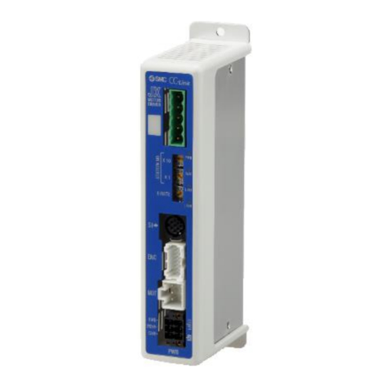
3.2 Parts Description Details of the parts of the controller. Side (Controller version) ② VZ S3.4T3.3 ③ ① ⑩ ④ ⑨ ⑤ ⑥ S0819120001 ⑦ Label of Controller version ⑧ ⑪ A side Display Name Details LED's to indicate the controller status. ①... -
Page 21: External Dimensions
3.3 External Dimensions The appearance of this product is as shown in the diagram below: (1) Screw mounting (JXCM17#-#) For body mounting (Screw mounting type) (2) DIN rail mounting (JXCM18#-#) 35mm DIN rail mountable - 20 - No.JXC#-OMX0009-A... -
Page 22: Mounting
3.4 Mounting (1) Mounting The controller can be direct mounted using screws or mounted on a DIN rail. Details of the controller mounting options are shown below. ① Screw mounting (JXCM17#-#) ② DIN rail mounting (JXCM18#-#) (Mounting with two M4 screws) (Mounting with DIN rail) DIN rail is locked Ground wire... -
Page 23: 3) Mounting Location
Caution ①A dedicated Ground connection must be used. Grounding should be to a D-class ground (ground resistance of 100Ω or less). ②The cross sectional area of the grounding cable shall be 2mm minimum. The Grounding point should be as near as possible to the controller. Keep the grounding cable as short as possible. -
Page 24: Precautions For Electric Actuator Installation
(4) Precautions for electric actuator installation Warning Do not use in an environment where strong magnetic field are present. A magnetic sensor is used in the encoder. Therefore, if the actuator motor is used in a strong magnetic field environment, malfunction or failure may occur. Do not expose the actuator motor to a magnetic field with a magnetic flux density of 1 mT or more. -
Page 25: Initial Setting
The communication speed of CC-Link setting at the time of the factory shipment is set in “0" (156kbps). Example) When 3 controllers tie as follows by 2 stations occupation (The communication speed of CC- Link is 10Mbps) JXCM1 (1) to (3) Set the number of occupied CC-Link... -
Page 26: Parameter Setting
4.2 Parameter Setting Set the parameter of occupied number of stations and operation setting at the time of the communication error of JXCM1. The set item is shown below. ●Occupied number of stations setting Set Occupied number of stations in "Optional setting 1" of basic parameter item. -
Page 27: Plc Setting
Special register (SW) ● Station information setting Set Occupied number of stations of JXCM1 which connected to the PLC. Please set the value same as Occupied number of stations of “Optional setting 1” of Basic parameter. Occupied number of stations of LECPMJ is set in “2” for shipment. -
Page 28: External Connections
5. External Connections An example of standard wiring of the controller is shown for each connector. 5.1 PWR: Power supply connector Controller Controller input power supply 24VDC Wire (The Controller power supply (24VDC) and wires must be prepared by the user.) Refer to 6. -
Page 29: Connection With A Pc
(2) Connection with a PC Controller USB cable Communication cable (A-miniB type) When using the LEC-W2, it is necessary to connect (PC is prepared by the user.) a conversion unit (P5062-5) to the communication cable. 5.4 CC-Link communication connector Controller Special communication cable for CC-Link CC-Link... -
Page 30: Details Of Power Supply Plug
6. Details of Power Supply Plug 6.1 Power supply plug specifications The specifications of the power supply plug supplied with the controller are shown below. Power supply plug Pin No. Terminal Function Functional explanation C24V Power supply (+) The positive control power. The positive power for the actuator M24V Motor power (+) -
Page 31: Power Supply Plug Wiring
6.3 Power Supply Plug Wiring Connect the power supply plug to the 24VDC controller power supply according to instructions (1) (2) and (3) and then insert it into the PWR connector of the controller. (1) Wiring of power supply (C24V, M24V, 0V) Connect the positive of the 24VDC controller power supply to the C24V and M24V and connect the negative of that power supply to the 0V terminal. -
Page 32: Wiring Of Shutdown Circuit
6.4 Wiring of shutdown circuit The actuator stops its operation when the external shutdown switch or the shutdown switch of the teaching box is activated. (1) Example circuit 1- Single controller with teaching box When the controller recognizes the connection of the teaching box, the shutdown of the teaching box is activated. -
Page 33: Stop (Relay Contact (1))
(2) Stop (relay contact (1)) If the system where this controller is installed has a stop circuit for the whole system, or if the system has multiple controllers with individual power supply, relay contacts should be made between the 24VDC controller power supply and the EMG terminal of the power supply plug. (Circuit example) 24VDC The stop is... -
Page 34: Motor Power Shutdown (Relay Contact (2))
(3) Motor power shutdown (relay contact (2)) If it is necessary to have a circuit to shutdown the motor power externally, relay contacts should be made between the 24VDC controller power supply and the M24V and EMG terminal of the power supply plug. -
Page 35: Communication Plug Connector
7. Communication Plug Connector 7.1 Wiring The communication plug connector specification of the optional product is shown below. Straight type T-Branched type LEC-CMJ-S LEC-CMJ-T Manufactured by Phoenix Contact Manufactured by Phoenix Contact Part no:MSTB2,5/5-ST-5,08 AU Part no:TMSTBP2,5/5-ST-5,08 AU Designation Description CC-Link communication line A CC-Link communication line B CC-Link ground line... -
Page 36: Electric Wire Specification
7.2 Electric wire specification Item Specifications Applicable wire size AWG 24 to 12 (0.2 to 2.5mm (Single line, stranded wire) The rated temperature for the insulation coating: 60 C or more LEC-CMJ-S:7mm Stripped section length LEC-CMJ-T:10mm 7.3 Wiring of communication plug connector Please wire the CC-Link communication cable to the communication plug connector, and then insert it into CN5 connector of controller. -
Page 37: Led Display
8. LED display 8.1 LED display Refer to the table below for details of the LED status. Details Power is not supplied Power supply and EEPROM writing Green LED is ON Power is supplied status Green LED is flashing EEPROM writing Normal operation Controller alarm status. -
Page 38: Mode
9. Mode 9.1 Outline This controller has 3 types of operation mode (Single numerical data instructions, Half numerical data instructions, Full numerical data instructions). These modes can be changed by registering the occupied number of Stations with basic parameter "Option setting 1" of the controller. The following describes the details for each mode. -
Page 39: Position / Speed Monitor
9.3 Position / speed monitor The current position and the current speed of the information of the controller can be read by turning on controller control flag “RWw0, bit0: Setting read numerical data “of the remote register. 9.4 Operation by numerical instruction The electric actuator operates according to the value that specifying the position and the speed, etc. -
Page 40: Data Editing Function
9.5 Data editing function A function to read and write the step data and number of occupied stations in the controller’s built-in microcomputer as well as read the state data to/from CC-Link. Please refer to the instruction manual for the teaching box, or to the controller setting software for details of the function for editing the step data and other items. - Page 41 ・Basic parameter addresses Controller memory Name Words Input range Unit address Controller ID Upper-level 1 to 32 - (0000)h I/O pattern Lower-level Fixed value - byte Acceleration/deceleration pattern Upper-level Fixed value - byte (0001)h S-motion rate Lower-level byte - (0002)h Stroke (+) 0.01 mm byte...
- Page 42 ・JOG motion data addresses (motion parameter items) Controller memory Unit Name Word Setting data range address (0030)h JOG speed 1mm/s ) 1 to “Max ACC/ DEC” of the basic (0031)h JOG acceleration 1mm/s parameter 1 to “Max ACC/ DEC” of the basic (0032)h JOG deceleration 1mm/s...
-
Page 43: Memory Map
10. Memory map 10.1 Remote IO (Rx and Ry) List and details of remote IO according to the mode are shown as follows Address Rx00、Ry00 corresponds to initial address of Remote IO memory allocated in masters. (1) Controller → Higher level device [IN] (Remote to Master) PLC memory Single numerical data Half numerical data... - Page 44 (3) Controller → Higher level device [IN] (Remote to Master) Signal name memory address Description Single Half numerical Full numerical numerical data data data instructions instructions instructions When the operation is started and “DRIVE” is turned OUT0 OFF, the step No. executed by “DRIVE” will be refreshed/updated by the combination of “OUT0”...
- Page 45 The condition when “INP” turns ON depends on the electric actuator action. •Return to origin Turns ON at the origin when within the ±"default iIn position" in the Basic parameters. •During positioning operation Turns ON when the current position is within "Step data position ±...
- Page 46 CC-Link 30 to 3A - system area ● Only at Half numerical data instructions Remote The content of Remote station READY is as station same as at Single numerical data instructions. READY Please refer to the content of Rx1B. (No used) CC-Link 3C to 3F -...
- Page 47 (4) Higher level device → Controller [OUT] (Master to Remote) Memory Signal name Description address Single Half numerical Full numerical numerical data data data instructions instructions instructions Bit no. to specify the step data (Specify the number by combining On/Off of the terminals.) E.g.) Step data No.
- Page 48 Jogging in the (-) direction. The electric actuator moves when the signal is ON. Stops when the signal is OFF. When the "FLGTH" (signal for switching Jogging and JOG(-) Inching) is ON, the electric actuator inches toward the (-) side as the "JOG (-)" signal increases. INP output, OUT0 to 5 are OFF after Jogging/ Inching start.
-
Page 49: Remote Register (Rwr And Rww)
10.2 Remote register (RWr and RWw) List of remote register according to the mode are shown as follows. In Half numerical data instructions and Full numerical data instructions the memory assignment is different according to the function to use. The change of Numerical data instructions operation function and Step data editing function uses RWw0, bit1: Setting parameter rewriting. - Page 50 RWw10 Moving force RWw11 Area 1 RWw12 RWw13 Occupation Area 2 area RWw14 RWw15 In position “Occupation area” is an area that secured compulsorily by JXCM1. JXCM1 does not exchange data with PLC in “Occupation area” - 49 - No.JXC#-OMX0009-A...
- Page 51 (3) Details: Numerical data instructions operation function ● Controller → Higher level device [IN] (Remote to Master) [Single numerical data instructions] PLC memory RWr Data name address Content Single numerical data instructions Current occupied number of stations is shown. Return of Occupied Occupied number of stations number of stations (L) 1 Stations occupied...
- Page 52 [Half numerical data instructions, Full numerical data instructions] RWr data name PLC memory address Half numerical Full numerical Content data data instructions instructions Return of Occupied number of stations (L) Return of Occupied number of stations (H) Sending As same as Single numerical data instructions. Sending completed Please refer to "10.2 Remote register (RWr and RWw)"...
- Page 53 ● Higher level device → Controller [OUT] (Master to Remote) [Single numerical data instructions] PLC memory RWw Data name address Content Single numerical data instructions Setting read Turn ON to enable reading the numerical data such as the numerical data current position or current speed.
- Page 54 [Half numerical data instructions, Full numerical data instructions] PLC memory RWw data name Content address Half Half numerical numerical Unit data data Setting data range instructions instructions Turn ON to enable reading the numerical data such Read numerical data flag as current position or current speed.
- Page 55 7 to 0 Trigger LV F to 8 7 to 0 Pushing 1mm/s speed F to 8 7 to 0 Moving force F to 8 F to 0 “Stroke (-)” Area 1 0.01mm “Stroke (+)” of the F to 0 basic parameter F to 0 “Stroke...
- Page 56 (4) Data editing function ●Controller → Higher level device [IN] (Remote to Master) RWr data name PLC memory address Full Contents Half numerical numerical data instructions data Current occupied number of stations is shown. instructions Return of Occupied Occupied number of stations number of stations (L) 1 Stations occupied 2 Stations occupied...
- Page 57 F to 0 The current position of the electric actuator is shown in multiples of 0.01 mm when numerical data reading is enabled. Current position Example) F to 0 800.00mm (80000d=13880h) is output: RWr1=3880h RWr2=0001h 7 to 0 ● Half numerical data instructions The executed instruction code is output.
- Page 58 ●To upper level device from the controller [IN] (to base module from the remote module) - continued PLC memory RWw data name address Full Half numerical Content numerical data data instructions instructions ● Half numerical data instructions 0 is always output. Address F to ●...
- Page 59 The data of the executed instruction code is output. F to 0 DATA(H) Error code is output in abnormal conditions. The data of the executed instruction code is output. F to 0 DATA(L) 00h is output in abnormal conditions. F to 0 Occupation -...
-
Page 60: Settings And Data Entry
11. Settings and Data Entry In order to move the electric actuator to a specific position, it is necessary to setup the patterns of operations with a PC (with the controller setting software) or the teaching box or record data. This setup data input by the software or teaching box will be recorded in the memory of the controller. - Page 61 Step Data details Description Controller Teaching Range Explanation setting software (TB) Step No. 0 to 63 Number of the step data. Specifies the co-ordinate system for the target position. Software Details Blank Disable The step data is ineffective. 3 types Movement Movement (Refer to the table...
- Page 62 ■Effective only for the pushing operation (when the value for the "Pushing force" is from 1 to 100). This defines the movement speed during the pushing operation. If Minimum value to “Max this Speed is too high, it may cause damage to the actuator or Pushing Pushing force”...
-
Page 63: Basic Parameters
11.2 Basic parameters The "Basic parameter" is the data to define the operating conditions of the controller, conditions of the actuator, etc. Caution Writing of the parameter should be performed while the electric actuator is stopped. Activation: “XX” = Become effective just after recorded into the controller “X”... - Page 64 This defines the position of the actuator after the return to origin operation.(Unit: mm) ■ The ORIG offset is 0 (mm). Actuator In the examples on the left, the Controller recognizes actuator positions are not different Position after return to origin but the reference point that the position (0mm) ■...
- Page 65 4. Click "Download" to transmit the change. The text colour of the changed parameter will change from blue to black. 5. After completing the setting, turn the JXCM1 OFF then ON to make the change effective. - 64 - No.JXC#-OMX0009-A...
-
Page 66: Return To Origin Parameter
11.3 Return to origin parameter “ ” Return to origin parameter is the setting data for the return to origin operation. Activation: “XX” = Become effective just after recorded into the controller “X” = Become effective after restarting the controller “-”= The parameter cannot be changed (fixed value) Details of Return to origin parameter Parameter name... -
Page 67: Operation Parameters
11.4 Operation parameters This is data to set the JOG operation of the controller. To change operation parameters, set the basic parameter "Parameter protection" to "3: Common + Extend + Step". Details of the operation parameters Activation: “XX” = Become effective just after recorded into the controller, “X”... -
Page 68: Operations
12. Operations 12.1 Return to origin position Return to origin operation should be performed first in the following cases:. (1) When power is applied for the first time. (2) When the actuator or motor is replaced. “ ” (3) When alarm Group E is cleared by applying the power again. -
Page 69: Pushing Operation
12.3 Pushing Operation The pushing operation is active when the value of the "Pushing F%" in the Step data is set to "1" or more. Similar to the positioning operation, the actuator moves according to the settings of "Position" and "Speed"... -
Page 70: Controller Input Signal Response Time
[2] Movement of the workpiece in the direction opposite to the pushing direction (The actuator is pushed back since the reaction force from the workpiece is too large.) After completion of the pushing operation, if the reaction force from the workpiece becomes larger, the actuator may be pushed back. -
Page 71: Operation Examples
13. Operation Examples 13.1 Positioning Operation E.g.) Move an actuator from the origin to 100mm point at 50mm/s. (Step No.1 instruction) Next, move the actuator from the 50mm point to 100mm point by moving it 5 times continuously, 10mm at a time, at a speed of 50mm/s. (Step No. 2) ... -
Page 72: Pushing Operation
13.2 Pushing Operation Eg.) Move the actuator from the origin to a point 100 mm away at 100 mm/s. (Step Data No.1 is used for this operation). From the 100 mm point, the actuator must start a pushing operation of 10 mm/s speed and 50% or less force. -
Page 73: Start Up Procedure For Battery-Less Absolute Encoder
14. Start up procedure for battery-less absolute encoder 14.1 Procedure for start up Procedure for start up of the battery-less absolute encoder for every occasion when the power is applied. When power is supplied for the first time (Refer to 14.2 for details) In the following cases, Alarm No.10-153 “Absolute encoder ID does not match controller data”... -
Page 74: When Supplying Power For The First Time
14.2 When supplying power for the first time Please refer to the following [Procedures and Timing diagram] for each operation. -Procedure- -Timing diagram- 1) Supply power ↓ 2) ESTOP output is turned OFF Power ALARM output is turned ON OUT3 output is turned ON ([1-153: Absolute encoder ID does not match controller data] alarm is ・... -
Page 75: Supply Of Power
14.3 Supply of power (1) Power supply is turned back on (Normal) If [ALARM] is OFF (no alarm) after supplying power again, SETON output is ON after T3. -Procedure- -Timing diagram- 1) Supply power ↓ 2) ESTOP output is turned OFF Power ALARM output is turned OFF ↓... -
Page 76: Alarm (Group E) Is Cleared By A Cut To The Power Supply
14.4 Alarm (group E) is cleared by a cut to the power supply It is necessary to perform the return to origin operation when alarm (group E) is generated and the alarm is cleared by shutting off the power supply. When the power is applied again after changing Return to origin parameter “Return to Origin Direction”, follow the same start up procedure. -
Page 77: Operation Instructions
15. Operation Instructions The following describes how to instruct the operation by step data No. instruction, operation by numerical instruction, and operation of the data edit function. 15.1 Operation procedure for Operation by Step date No. Refer to the following "Procedures" and "Timing charts" for details of the Return to Origin, operation mode procedures and the signal timing. -
Page 78: Positioning Operation
[2] Positioning operation - Procedure - - Timing chart Positioning operation - ① Input step data No. (“IN0” to “IN5”) Input the step data no. Scan the step data no. ↓ ②Turn ON the "DRIVE".(OUT0 to OUT 5 is turned off) →Scan the step data number (From IN0 to IN5). -
Page 79: Hold
[4] HOLD - Procedure - - Timing chart HOLD - ① During operation (“BUSY” is ON), Input HOLD turn ON “HOLD”. ↓ Output BUSY Deceleration ②“BUSY” turns OFF. starts Electric actuator (The actuator stops.) 0mm/s ↓ Speed ③Turn OFF the “HOLD”. HOLD during the operation ↓... - Page 80 [7] Area output - Procedure - - Timing chart Area output - ● Step data No.1 operation The initial position: 50mm ①Input step data No.(“IN0” to “IN5”) ↓ Operation of step data No.1: Position: 200mm, Area1-Area2: 150-250mm ②Turn "DRIVE" Operation of step data No.2: Position: 100mm, Area1-Area2: 130-170mm ⇒Receive the step data no.1 IN0~IN5 (from “IN0”...
-
Page 81: Operation Procedure For Operation By Numerical Instruction
15.2 Operation procedure for Operation by numerical instruction Operation by numerical instruction is possible in all modes. The following shows an example in the half numerical data instruction mode. Enter half numerical data instruction mode and numerically instruct 50.00 mm directly for the position parameter of the specified step data No., and then operate the electric actuator. -
Page 82: Operating Procedure For The Data Edit Function
⑦When the actuator reached the target position, Rx0B: INP=ON is output. (Refer to 10. Memory map for signal ON conditions) When the actuator stops, Rx08: BUSY=OFF will be output. The completion of the actuator operation is validated when both Rx0B: INP=ON and Rx08: BUSY=OFF are established Please refer to "10.1 Remote I/O (Rx and Ry)"... - Page 83 (7) Check that data is being transmitted and the transmission is completed by using the same procedures described in (3) and (4). When data transmission is completed, [Position] of the step data No. 1 is output to the remote register RWr6 to 7: DATA.
-
Page 84: Alarm For Motor Control
16. Alarm for Motor Control The details of the alarm can be checked using the controller setting software or the teaching box. Please refer to the manuals of the controller setting software or the teaching box for details of the alarms. When an alarm is generated, deactivate the alarm after troubleshooting and correcting the error with reference to chapter "16.2 Alarms and countermeasures". -
Page 85: Alarms And Countermeasures
16.2 Alarms and countermeasures Controller How to setting software Teaching box Alarm contents/Countermeasure deactivate (code) 1 <Condition> The step data is incorrect for the following conditions (Settable range) (1) Area1 <Area2 (If both Area1 and Area2 is 0, the alarm will not be activated.) (2) Trigger LV ≤... - Page 86 <Contents> For an operation for a specific step data no., the requested number of the step data is not registered. (When operation is commanded through PLC, this alarm will be generated depending on the signal interval and the holding time of signals) Set step data <...
- Page 87 <Content> The actuator goes outside the stroke limit specified by the basic parameters, "Stroke (+)" and "Stroke (-)" if it performs the requested operation during numerical instruction operation. <Countermeasure> Make sure the basic parameters, "Stroke (+)" and "Stroke (-)" are Alarm consistent with the distance of actuator movement specified in the step _Comment...
- Page 88 <Contents> Absolute When an error is detected in the communication with the absolute encoder encoder when power is applied. AbEnc Input communication When the wiring of the encoder and controller is disconnected. Comm ALM RESET error. <Countermeasure> (01-106) Check the connector of the controller and actuator wiring is not loose or the cable is not damaged.
- Page 89 <Contents> The control power supply voltage within the controller is outside the set range. Controller <Countermeasure> supply Make sure that the voltage supplied to the control power (C24V) of the voltage is RESET Over controller is appropriate. outside set SVON CrtlVol Caution range.
- Page 90 <Contents> This alarm is generated when connection fails while the electric actuator is operated from an upper-level device. ountermeasure> <C Do not interrupt the connection between the PC and teaching box when the electric actuator is being operated by upper-level devices.
- Page 91 <Contents> An abnormality is detected by the current sensor that is checked when the controller is reset. Turn OFF and ON <Countermeasure> the power I sens ALM I sens ALM Make sure that the electric actuator conforms to the controller. supply (1-195) When a command to turn on servo is given, check if LK RLS is...
-
Page 92: Alarm Detection For Cc-Link Communication
Turn ON Check the connection with the upper-level device, and the reset then reset the alarm according to the state of the L flag, and RUN LED on the PLC and the JXCM1 flag status. CC-Link then input JXCM1 Commun... - Page 93 Commun <Contents> ication When Rotary Switch (B RATE) is set within the range speed Green (5 to 9) of unused, the alarm will be occurred. flashi Power off error <Countermeasure> (unused Please confirm whether the setting of Rotary Switch range) (B RATE) is correct.
- Page 94 <Countermeasure> Please confirm whether the ‘Setting numerical data’ flag and the data at the time of parameter rewriting is correct. <Contents> Abnormality of the communication system in the JXCM1 controller. Turn on Abnormal <Countermeasure> RWw0,bit 2: station Reset flag or...
-
Page 95: Precautions For Wiring And Cable
18. Precautions for wiring and cable Warning (1) Adjusting, mounting or wiring change should never be done before shutting OFF the power supply to the product. Electric shock, malfunction and damage can result. (2) Do not disassemble the cable. Use only specified cables. (3) Do not connect or disconnect the cable or connector with the power on. -
Page 96: Electric Actuators/Common Precautions
(11) The Speed/pushing force may vary, depending on the cable length, load and mounting conditions etc. If the cable length exceeds 5m, the speed/pushing force will be reduced 10% per 5 m maximum. (If cable length is 15m, 20% reduction maximum.) 【Transport】... -
Page 97: Mounting
Caution (1) Use the product for the maximum usable stroke. The product will be damaged if it is used with a stroke exceeding the maximum stroke. Refer to the specifications of the product. (2) When the product repeatedly cycles with partial strokes, operate it at a full stroke at least once a day or every 1,000 strokes. -
Page 98: Handling Precautions
(9) When mounting the actuator or attaching to the work piece, do not apply strong impact or large moment. If an external force above the allowable moment is applied, it may cause looseness in the guide unit, an increase in sliding resistance or other problems. (10) Ensure sufficient space for maintenance activities. -
Page 99: Operating Environment
[Grounding] Warning (1) Provide a good earth connection to the actuator. (2) The earth should be a dedicated earth connection. Class D dedicated grounding should be used. (Ground resistance 100Ω or less) (3) The earth cable length should be as short as possible. [Unpacking] Caution (1) Check that the received product is as ordered. -
Page 100: Maintenance Precautions
19.5 Maintenance Precautions Warning (1) Do not disassemble or repair the product. Fire or electric shock can result. (2) Before modifying or checking the wiring, the voltage should be checked with a tester 5 minutes after the power supply is turned OFF. Electric shock can result. -
Page 101: Controller And Peripheral Devices/Specific Product Precautions
(7) When the actuator is operated manually (when “SVRE” signal is OFF), supply 24VDC to the [LK RLS] terminal of the power supply connector. If the product is operated without releasing the lock, wear of the lock sliding surface will be accelerated, causing a reduction in the holding force and the life of the locking mechanism. -
Page 102: Mounting
(7) Do not touch the product when it is energized and for some time after power has been disconnected, as it can be very hot. It may cause burns due to the high temperature. (8) Check for voltage using a tester at least 5 minutes after power-OFF when performing installation, wiring and maintenance. -
Page 103: Wiring
20.4 Wiring Warning (1) Do not damage the cable or apply a heavy object or pinch the cable. Avoid repeatedly bending or stretching the cable. It may cause an electric shock, fire, or breaking of wire. (2) Wire correctly. Incorrect wiring could damage the controller or its peripheral devices depending on the seriousness. (3) Do not perform wiring while the power is on. -
Page 104: Maintenance
20.7 Maintenance Warning (1) Perform maintenance checks periodically. Confirm wiring and screws are not loose. Loose screws or wires may cause unexpected malfunction. (2) Conduct an appropriate functional inspection and test after completing maintenance. In case of any abnormalities (if the actuator does not move, etc.), stop the operation of the system. Otherwise, an unexpected malfunction may occur and it will become impossible to ensure safety. - Page 105 (2) Check whether there are any loose connections between the controller and actuator. If contact failure occurs with the motor powerwiring, the motor power will be insufficient, which reduces the holding force. Because of this, the actuator moving part will fall downward in a vertical operation. (In this operation, the lock function of the actuator with lock does not work).
-
Page 106: Troubleshooting
It is possible that this product may be damaged due to the operating conditions (applications). Please contact SMC to discuss appropriate measures. The system does not work correctly. JXCM1 LED is OFF. Refer to Failure 1 Either one of L RUN or L ERR is turned Refer to Failure 2 ON or is flashing. - Page 107 Investigation method and Problem Possible Problem location of possible Countermeasures causes causes Check the voltage and current supplied to the controller. Is the green LED on the Power fault ⇒ 5. External Connections controller ON? ⇒ 6. Details of Power Supply Plug Check if the wiring is connected correctly or if there is broken wire or short-circuit by referring to this Operation Manual.
- Page 108 When the unlock switch If there is no sound of lock release, the lock Lock release is turned ON or OFF brake may be broken. error there is an unlocking ⇒ If the problem persists, please contact sound made. SMC. Check the operation by test run using the Check that the PLC controller setting kit, etc.
- Page 109 Check that “INP” turns ON during a pushing operation. Failure of Check “INP” signal before the energy saving (If completion of the mode is turned ON. pushing pushing operation is ⇒ 10. Memory map operation. detected by “INP”, the PLC cannot confirm completion) Check that the combination of the...
- Page 110 Check if the wiring is connected correctly or if there is broken wire or short-circuit by referring to this Operation Manual. Correct the wiring and check that the input/output of each Incorrect signal is correct. Is the wiring connected wiring Separate the power supply for the correctly? CN1controller and the CN5 I/O signal power...
- Page 111 Check for a temporary voltage drop in the power supply? (If there is a temporary There is a possibility of a momentary voltage voltage drop in the power drop because the capacity of the power supply, the EMG terminal supply is insufficient, or if the power supply is Voltage drop of CN1 power connector "inrush-current control"...
-
Page 112: Memory Map List
22. Memory map list The memory map according to the mode is shown below. Please refer to 10. Memory map for details “ ” of each signal. ●Single numerical data instructions (1 Stations occupied) [Remote IO] PLC memory PLC memory address Signal name address... - Page 113 ●Half numerical data instructions (2 Stations occupied) [Remote IO] PLC memory PLC memory Signal name Signal name address address OUT0 OUT1 OUT2 OUT3 OUT4 OUT5 - - - - BUSY HOLD SVRE SVON SETON DRIVE RESET AREA SETUP WAREA JOG(-) ESTOP JOG(+) ALARM...
- Page 114 Address Acceleration F to 0 F to 0 DATA(L) Target (Pushing force) (always 0) position Deceleration F to 0 DATA(H) F to 0 (Trigger LV) Occupation 7 to 0 Alarm 1 Pushing area DATA(L) F to 0 F to 8 speed Alarm 2 *4) Set always OFF(0)
- Page 115 ●Full numerical data instructions (4 Stations occupied) [Remote register] memory RWr Data name memory RWw Data name address address Numerical data Numerical data instructions Data editing instructions Data editing operation operation Return of Occupied number of Setting read numerical data stations (L) Return of Occupied number of Setting parameter rewriting...
-
Page 116: Handling Remote Registers
RWw), depending on the data content. 23.1 Relationship of bit data, byte data, and word data The following describes the relationship of each bit data, byte data, and word data for the JXCM1. ● 1-bit data This indicates the OFF state (0) and ON state (1) by using one of the two types of data, "0" or "1". -
Page 117: Relationship Of Binary (Bin), Decimal (Oct), And Hexadecimal (Hex) Numbers
23.2 Relationship of binary (BIN), decimal (OCT), and hexadecimal (HEX) numbers The following describes the relationship of binary (BIN), decimal (OCT), and hexadecimal (HEX) numbers. Hexadecimal Decimal Binary E.g.) 1 byte (OCT) (HEX) (BIN) - 116 - No.JXC#-OMX0009-A... -
Page 118: Installation
23.3 Installation 1 byte data Please treat 1 byte data of the alarm as follows. When Alarm 1 and Alarm 2 are displayed in RWwn+7. (Full numerical data instructions, 4 Stations occupied) Alarm 1 and Alarm 2 are expressed by the decimal number. Display form of the value of RWrn+7 is different according to the setting of PLC. -
Page 119: Definitions And Terminology
24. Definitions and terminology The major terminology used in this Operation Manual is stated below. Term Definition It is a standard of the field bus that Mitsubishi Electric Corporation etc. CC-Link promote. The share in the Asian area and Japan is high and CC-Link is used mainly in a large number of companies. - Page 120 Revision history A: Contents revised in several places. [Nov 2020] 4-14-1, Sotokanda, Chiyoda-ku, Tokyo 101-0021 JAPAN Tel: + 81 3 5207 8249 Fax: +81 3 5298 5362 https://www.smcworld.com Note: Specifications are subject to change without prior notice and any obligation on the part of the manufacturer. ©...
Need help?
Do you have a question about the JXCM1 and is the answer not in the manual?
Questions and answers