Table of Contents
Advertisement
Quick Links
Advertisement
Table of Contents

Related Manuals for Omicron DANEO 400


Summary of Contents for Omicron DANEO 400
- Page 1 DANEO 400 User Manual...
- Page 2 The user is responsible for every application that makes use of an OMICRON product. OMICRON electronics translates this manual from the source language English into a number of other languages. Any translation of this manual is done for local requirements, and in the event of a dispute between the English and a non-English version, the English version of this manual shall govern.
-
Page 3: Table Of Contents
Rules for use ..........................9 2.2.1 Orderly practices and procedures ....................9 2.2.2 Operator qualifications ........................ 9 2.2.3 Safe operation procedures ......................9 DANEO 400 overview ........................11 Designated use ........................11 Key features ........................... 11 Distributed system ........................12 Hybrid measurement ...................... - Page 4 Recordings ..........................59 Time ............................59 System ........................... 59 6.7.1 Status ............................59 6.7.2 Licenses information ......................... 59 DANEO 400 hardware ........................61 Front panel ..........................61 Rear panel ..........................62 Flexible housing ........................62 Technical data ..........................63 Guaranteed values ......................... 63 Power supply ..........................
- Page 5 Contents Glossary ..............................75 Support ..............................77 Index ..............................79...
-
Page 6: Preface
DANEO 400. The acquisition and analysis with DANEO Control are explained in detail. The web interface is presented. DANEO 400 hardware is addressed including the technical data. Software license information is also included. -
Page 7: Documentation Overview
Preface Documentation overview The DANEO 400 documentation comprises the Quick Start Guide, the User Manual, and the DANEO Control Help. Quick Start Guide The Quick Start Guide is delivered in printed format and provides the steps to set up the test interface and install DANEO Control. -
Page 9: Safety Instructions
Safety instructions Before operating DANEO 400, carefully read the following safety instructions. Only operate (or even turn on) DANEO 400 after you have read this User Manual including the “Technical data” chapter and fully understood the instructions herein. For your safety DANEO 400 may only be operated by trained personnel. - Page 10 DANEO 400 • If DANEO 400 seems to be functioning improperly, please contact the “OMICRON Service Centers” on page 75.
-
Page 11: Daneo 400 Overview
Typical applications are in factory acceptance tests (FAT), site acceptance tests (SAT), commissioning, and troubleshooting. DANEO 400 is a portable device for temporary use. It is not designed to perform mission critical operational tasks in 24/7 applications. The device is intended for commercial use operated by trained personnel and is not suited for private use. -
Page 12: Distributed System
The options for controlling DANEO 400 were made in a way so that remote access is possible. DANEO Control software is designed to control multiple devices from one place and to collect the acquired data from all devices of the measurement system for a coordinated analysis. -
Page 13: Connections And Interfaces
B and vice-versa. For capturing, it can still be selected from which of the two ports the incoming traffic is to be captured. In tap mode is not possible to control DANEO 400 through one of the process ports. -
Page 14: Usb Control Port
SV streams) it is preferred to use the process ports. USB control port DANEO 400 can also be controlled via the USB port that is also located in the CONTROL group on the front panel. The control via the USB port is a convenient option when the controlling PC is located close enough to DANEO 400. -
Page 15: Examples Of Network Connection Options
Connections and interfaces Examples of network connection options Due to the multiplicity of process ports, control ports, and usage options for the individual ports, there are a huge number of possible connections. Each of these options may be suited in certain applications and several options may similarly serve an application. - Page 16 Ethernet cables of sufficient length are available. CO02 – Control via ETH over network, capturing on A and B CO02 – The PC with the control SW is not directly connected to DANEO 400. The control traffic is also Figure 4: forwarded through the network, so the controlling PC can be located independently of DANEO 400.
- Page 17 (STP) algorithm will disable a network link. CO04 – Tapping a trunk link CO04 – The Ethernet ports A and B are configured as a tap. DANEO 400 is inserted into the link Figure 6: between switches and can capture all traffic exchanged over this link.
- Page 18 DANEO 400 CO05 – Tapping an edge link CO05 – The Ethernet ports A and B are configured as a tap. DANEO 400 is inserted into the link Figure 7: between switches and an end device (IED) and can capture all traffic of this IED.
- Page 19 Connections and interfaces Single DANEO 400 with explicit synchronization To time stamp the captured data with accurate absolute time, DANEO 400 needs to be time synchronized, that is connected to a PTP clock. The following scenarios can also be part of a measurement system with multiple DANEO 400 devices.
- Page 20 PC and the PTP clock, a PTP capable switch (transparent switch) has to be used. CO10 – Time synchronized capturing with control over the network Figure 12: CO10 – DANEO 400 is controlled over the network. Again, a transparent switch is needed to provide control and time synchronization to the ETH port.
- Page 21 Connections and interfaces CO11 – Time synchronized with PTP over the network Figure 13: CO11 – When the communication network is equipped with transparent switches and a PTP clock, DANEO 400 can use this infrastructure for time synchronization.
- Page 22 CO12 – Measurement system time synchronized with PTP over the network Figure 14: CO12 – With a PTP infrastructure on the communication network, time synchronization of multiple DANEO 400 devices is most easily established. No links for capturing traffic are shown in this figure.
- Page 23 Figure 16: CO14 – Even if the PTP infrastructure is not present in some locations, time synchronization can be established locally by using one of the options shown above in CO07 to CO10. DANEO 400 on the left captures traffic via port B. The kind of traffic obtainable depends in the port configuration at the switch (normal or mirror...
-
Page 24: Storage Interface
The setting to save recordings on this external mass storage is made in the Recording section (Storage) of DANEO Control. Extension Interfaces Accessories for DANEO 400 can be connected to these ports when available. Binary outputs These are four potential free relay contacts. The contacts can be activated by a post-trigger action to signal the detection of a trigger condition, for example to trigger other devices. -
Page 25: Daneo Control
DANEO Control DANEO Control This chapter introduces you DANEO Control, each functional section, and instructions to operate the application. Important topics are configuring the acquisition, recording, observing, and analyzing recordings. DANEO Control is divided into two major workspaces: Acquisition and Analysis. The following figure shows the home screen. -
Page 26: Acquisition
DANEO 400 Acquisition This section describes the necessary steps to create and configure a measurement system, configure the system under test, place devices and IEDs onto a substation network diagram, map GOOSE and Sampled Values streams to devices inputs, record, and observe signals. -
Page 27: Signal Pool Concept
DANEO Control 5.1.1 Signal pool concept The central point of the Acquisition is the Signal pool, which receives selected inputs in the form of hard wired signals or mapped signals. The selected signals work as the Signal pool output for recording and observation as shown by the following figure. -
Page 28: Measurement System
OMFIND. But also in LAN scenarios, there may be segregated broadcast domains set up or special filters set that prohibit the propagation of the OMFIND packets. In such cases, an assigned IP address has to be configured for a port on DANEO 400 prior to including it into a measurement system with DANEO Control. - Page 29 DANEO Control Connect to DANEO 400 locally via an Ethernet port and configure the IP address of an Ethernet port with DANEO Control software. Connect to DANEO 400 locally via an Ethernet port, locate the device in the OMICRON Device Browser and configure the IP address of the Ethernet port using the function Set Network Configuration from the context menu.
- Page 30 DANEO 400 Assigning IP addresses of the same subnet to more than one port of DANEO 400 has to be done with care. Depending on the network topology, this may lead to a condition where the control of DANEO 400 is interrupted.
- Page 31 All quantities for observation, recording, and analysis are treated as primary quantities within DANEO 400 and DANEO Control. At the analog inputs of DANEO 400, only voltages are measured, which are a proportional “image” of the primary quantities. Depending on the instrument transformers and/or sensors used, these voltages cannot even be always called secondary quantities in the classical sense.
- Page 32 The secondary circuit is terminated by a shunt with the value The primary quantity is the primary current: The voltage across the shunt is measured with DANEO 400: At nominal primary current we get: Current input: The instrument transformer is rated for the primary current and for the secondary current.
- Page 33 DANEO Control The primary quantity is the primary current: The output voltage of the current clamp measured with DANEO 400: At nominal primary current we get:...
-
Page 34: System Under Test
DANEO 400 5.1.3 System under test In System Under Test, you create the substation system. Therefore, load an SCL file including the GOOSE and Sampled Values or manually add an IED. Only selected IEDs are used for testing. The GOOSE and Sampled Values of the loaded substation system can be verified against the network. - Page 35 DANEO Control Configuring an IED You must configure a newly added IED before it can be used. You can also use this section to change an existing IED, and see or remove its GOOSE and Samples Values. To configure an IED: 1.
- Page 36 DANEO 400 The verification results are updated in real time and classed by means of three different icons. Found The control block reference (GOOSE) or SVID (SV), the data set, and the header match. Found with differences The control block reference (GOOSE) or SVID (SV) match, but not the data set or header.
-
Page 37: Network Diagram
DANEO Control 5.1.4 Network diagram In Network Diagram, you can import the substation network diagram and place the devices and the IEDs onto the diagram. The diagram can be useful for orientation while working in the substation. Importing and adjusting a network diagram Click Import diagram and choose a .jpeg or .png file. -
Page 38: Mapping
DANEO 400 5.1.5 Mapping In Mapping, you can map voltages, currents, and binary values, which are encapsulated in Sampled Values and GOOSE as well as hard-wired inputs and phase systems to specific devices. This way, you build up a signal pool for every device. - Page 39 DANEO Control Tip: Instead of dragging the port, double-click the port to map the signal in a quicker way. By repeating the above procedure for all desired signals, you map the analog and binary signals to the selected ports of every device. Remapping signals To remap signals, which are currently mapped to devices, you must first delete those signals from the Signal pool.
- Page 40 DANEO 400 Understanding the Properties section The Properties section displays the properties of the signal selected in the Signal pool. This section is read-only for analog signals and power systems. For mapped binary signals, you can define the Comparator to evaluate the GOOSE value.
-
Page 41: Recording
DANEO Control 5.1.6 Recording In Recording, you select for each device the signals and the network traffic per port for recording, set trigger conditions and post-trigger actions, and define the storage location on the device to save the recording files. Finally, you can arm the devices with the trigger conditions or start the recordings immediately. - Page 42 DANEO 400 Used IEDs Only traffic that belongs to the used IEDs in the system under test is recorded. Custom Only traffic whose destination MAC address, source IP address, and/or Ethertype have been entered manually is recorded. None No traffic is recorded.
- Page 43 DANEO Control Understanding and configuring the trigger settings The trigger settings comprise a pre-trigger time, a post-trigger time, a lockout period, and a re-arming option. Pre-trigger Represents the recording time before the trigger condition becomes true. The recorded data is stored in a buffer in the device. When you select Maximum, the whole data of the buffer will be stored into the recording.
- Page 44 DANEO 400 Configuring the post-trigger action With the post-trigger action, you can configure what the device outputs when the recording has finished. Possible actions are sending a GOOSE message or setting a binary output to a certain value. The GOOSE message can be used as a trigger input for another device.
-
Page 45: Observation
DANEO Control 5.1.7 Observation In the Observation, you can observe hard-wired and mapped analog/binary signals, as well as traffic. The following table shows the available measurements and their parameters. Measurements Signal parameters Analog signals Magnitude, phase, RMS, DC, frequency, and frequency change. In a phase system there are also magnitude and phase of the symmetric components (zero, positive, and negative). - Page 46 DANEO 400 Y-axis scaling To adjust the Y-axis range, click the Y-axis button (left of the graph). The Y-axis scaling dialog opens and you can click the buttons to set the custom value. When the button unit is percentage, the resulting values are derived from the nominal value.
-
Page 47: Tools
To enter default frequency, voltage, and current names. Voltages and currents in the primary and secondary are used as a conversion factor in DANEO 400 analog inputs. For example, a primary voltage of 110.00 kV and a secondary voltage of 100.00 V create a factor of 1.10 kV/V. - Page 48 DANEO 400 Firmware update The firmware update can be performed only for used devices that are either configurable, in recovery mode, or require a firmware update. An ongoing verification/sniffing, observation, recording, or just being armed will prevent the device from being upgraded.
- Page 49 DANEO Control License update There are two licenses for a DANEO 400 device. With the basic license you can measure and record conventional (analog and binary) signals. With the standard license you can additionally measure and record traffic from power utility communication networks and you get the IEC 61850 capabilities.
- Page 50 DANEO 400 Diagnosis Devices in the measurement system can be subject to a diagnosis. When the diagnosis is complete, you can save the diagnosis or send it to the technical support. The diagnosis cannot be started if the device is offline, locked by another user, armed, or in recording state. In these situations, you can save or send the PC log file.
-
Page 51: Analysis
DANEO Control Analysis In the Analysis workspace, you can access the Event view and add Time Signal Analysis or Propagation Delay views to run multiple analyses. You can analyze recordings located either on a reachable device or on a defined folder location on your local hard disk. Takes you to the home screen. -
Page 52: Collecting Recordings Of An Event
DANEO 400 To open the Help or the About dialog. To refresh the recordings from the defined sources. Sliding window to focus the diagram view to a specific time range. 5.2.1 Collecting recordings of an event Finding events—navigating on the timeline In the Event view you can search and select recordings to analyze. - Page 53 There is the possibility to directly open the exported file in an application associated to .cfg files, such as the OMICRON application TransView. These applications are not included in DANEO Control and have to be installed separately. For example, in case TransView is not found, the COMTRADE file is exported correctly and an error message is displayed.
-
Page 54: Time Signal Analysis
DANEO 400 5.2.2 Time signal analysis The list of devices and their recorded signals appear in the Navigation pane. By drag and drop or through double click, the signals are displayed in different types of diagrams. Available diagrams: Instantaneous signals: Instantaneous, cursor, and calculation ... -
Page 55: Propagation Delay Analysis
Figure 26: Propagation delay histogram showing the propagation delay of packets between two different locations captured by two different DANEO 400 units There are various filter options available. You can filter for a subset of all loaded recordings, for source and/or destination MAC address, for GOOSE, sampled values, and generic Ethertypes found at least in one of the PCAP files. - Page 56 DANEO 400 When creating a propagation analysis, you have to choose which location is the reference and which one is the investigated. The propagation analysis generates a histogram of the packet delay in relation to the reference recording.
-
Page 57: Web Interface
Homepage The DANEO 400 homepage in the figure below is displayed when connecting to DANEO 400 with a browser by specifying the device's IP address or URL. Clicking DANEO 400 logo in the upper left corner redirects to the homepage. -
Page 58: Network
DANEO 400 Recording: The device is recording. The Connected clients section shows the list of clients using the device, their IP address, and whether they are locking the device. The table shows one entry for each client connected to DANEO Control. Clients connected through the web interface appear only once as “Web interface”. -
Page 59: Recordings
Time The Time section is similar to DANEO Control. Refer to section “Configuring the time synchronization” on page 30 to understand its functionality. System 6.7.1 Status Some general information about DANEO 400 system: Product name Serial number ... -
Page 61: Daneo 400 Hardware
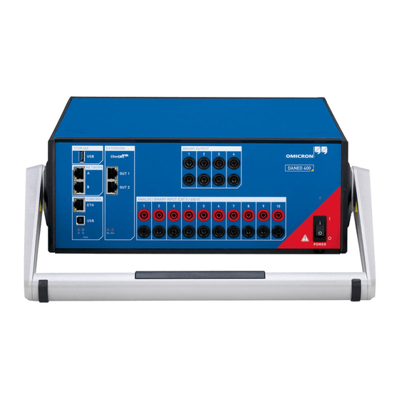
DANEO 400 hardware DANEO 400 hardware The DANEO 400 hardware interface is located at the front and rear panels of the device. Front panel 6 7 8 9 10 12 13 Ethernet network process ports USB 3.0 device port to connect external storage devices... -
Page 62: Rear Panel
For placing DANEO 400 on the floor, the handle can be used as floor stand as shown in the figure below. If the handle is not required (for example to stack multiple devices) you can easily stash it to the rear side of DANEO 400. -
Page 63: Technical Data
Technical data Technical data Guaranteed values The values are valid for the period of one year after factory calibration, within 23 °C ±5 °C at nominal value and after a warm-up time greater than 25 min. The given input/output accuracy values relate to the range limit value (% of range limit value). Power supply Main power supply Connection... -
Page 64: Magnitude Accuracy
DANEO 400 8.3.1 Magnitude accuracy The maximum measurement error is specified in the unit percent (%). The error composed by two parts, the first one referring to the actual reading and the second one referring to the measurement range. Maximum error... -
Page 65: Binary Inputs
Technical data Binary inputs Binary inputs: BINARY INPUT 1...10 Number of binary inputs Trigger criteria Potential-free or DC-voltage compared to threshold voltage Sampling frequency 10 kHz Time resolution 100 µs Max. measuring time unlimited 0 … 500 ms (refer to “Debouncing input signals” below) Debounce time 0 …... - Page 66 The debounce function is placed after the deglitch function described above and both are realized by the firmware of DANEO 400 and are calculated in real time. The figure below illustrates the debounce function. On the right-hand side of the figure, the debounce time is too short.
-
Page 67: Binary Outputs
Technical data Binary outputs Binary output relays: BINARY OUTPUT 1...4 Number of binary outputs AC loading =300 V AC; I =8 A; S =2000 VA DC loading =300 V DC; I =8 A; P =50 W (refer to load limit curve) Switch-on current 15 A (max. -
Page 68: Ethernet Ports
DANEO 400 Ethernet ports All Ethernet ports support Power over Ethernet (PoE) according to IEEE 802.3af and IEEE 802.3at. The accumulated output power of all PoE ports is limited to 75 W. 8.6.1 Control and network ports Ethernet ports ETH1 and ETH2... -
Page 69: Environmental Conditions
IP20 according to EN 60529 8.10 Cleaning To clean DANEO 400, use a cloth dampened with isopropanol alcohol or water. Prior to cleaning, always unplug all connectors so that all hazardous life parts are disconnected and the device is turned off. -
Page 70: Safety Standards, Electromagnetic Compatibility, Certificates
DANEO 400 8.11 Safety standards, electromagnetic compatibility, certificates CE conformity and requirements The product adheres to the specifications of the guidelines of the council of the European Community for meeting the requirements of the member states regarding the electromagnetic compatibility (EMC) Directive 2004/108/EC and the low voltage Directive 2006/95/EC. -
Page 71: Open Source Software License Information
Open source software license information Open source software license information Parts of DANEO Control software are under OMICRON license, other parts are under open source software licenses. DANEO 400 contains the following open source components: Open source component License type... - Page 72 DANEO 400 logagent Proprietary maio GPL2 mtd-utils GPL2 ncurses net-snmp nose LGPL omippc_kernel GPL2 omippc_pwr_fail GPL2 openresolv openssh openssl otpid Proprietary pita Proprietary procps GPL2 protobuf ptpdoo Proprietary Artistic2 pyro python rt-tests GPL2 subscomm Proprietary sval_sim Proprietary tcpdump tron_firmware_binaries Proprietary...
- Page 73 Open source software license information C:\Program Files\OMICRON\DANEO Control\OpenSource. Additionally, the license information can be displayed by launching DANEO 400 web interface and clicking the License Information hyperlink on the system page. DANEO Control software contains the following open source components:...
- Page 75 Glossary Glossary Configured IED Description DHCP Dynamic Host Configuration Protocol GOOSE Generic Object Oriented Substation Event IED Capability Description Intelligent Electronic Device Instantiated IED Description Internet Protocol Logical Device MAC address Media Access Control address OMFIND Protocol for finding devices on an Ethernet network Power over Ethernet (IEEE 802.3at) Precision Time Protocol (IEEE 1588, IEEE C27.238) Substation Configuration Language...
- Page 77 OMICRON Academy – Learn more www.omicron.at/academy www.omicronusa.com/academy Learn more about your product in one of the training courses offered by the OMICRON Academy. OMICRON electronics GmbH, Oberes Ried 1, 6833 Klaus, Austria, +43 59495...
- Page 79 Open source software license information .... 71 conventional signals ..........11 conversion factors ..........31 PCAP ..............53 PDF format ............. 7 DANEO 400 hardware main features ....11 Post-trigger ............43 DANEO Control software main features ....12 Power supply Device overview ........... 11 Technical data ..........
- Page 80 DANEO 400 Time ..............59 TransView ............53 Web interface ............57 wiring the terminals ..........9...
Need help?
Do you have a question about the DANEO 400 and is the answer not in the manual?
Questions and answers