Table of Contents
Advertisement
Quick Links
Advertisement
Table of Contents

Related Manuals for Omicron Bode 100


Summary of Contents for Omicron Bode 100
- Page 1 Bode 100 User Manual...
- Page 2 User Manual are not contractually binding. OMICRON electronics reserves the right to make changes at any time to the technology and/or configuration without announcement. OMICRON electronics is not to be held liable for statements and declarations given in this User Manual.
-
Page 3: Table Of Contents
2.2 Powering the Bode 100 ........ - Page 4 10.1 Bode 100 Specifications ........101...
-
Page 5: Using This Manual
This User Manual provides detailed information on how to use all functions of the Bode 100 vector network analyzer properly and efficiently. The Bode 100 User Manual is intended for all users of the Bode 100, providing instructions on the operation, usage, and measurement procedures. - Page 6 Bode 100 User Manual This page intentionally left blank...
-
Page 7: Introduction
Its concept – universal hardware controlled by the Bode Analyzer Suite software running on a PC – makes the Bode 100 an efficient and flexible solution for a wide spectrum of applications including: •... -
Page 8: Block Diagram
Bode 100 User Manual 1.2 Block Diagram Figure 1-1: Block diagram... -
Page 9: Connectors
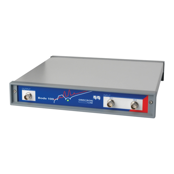
Introduction 1.3 Connectors Caution: To avoid damage of the Bode 100, check 10.3 "Absolute Maximum Ratings" on page 102 for maximum input signals at the CH 1 INPUT and CH 2 INPUT connectors and maximum reverse power at the OUTPUT connector. -
Page 10: Standard Compliance
Bode 100 User Manual 1.4 Standard Compliance The Bode 100 complies with the following standards: Table 1-1: Standard compliance Standard Description IEC 61326: EMC requirements Class B equipment Performance criterion B Universal Serial Bus (USB) Specification, USB interface Revision 1.1 and Revision 2.0... -
Page 11: Delivery
Test objects on a PCB: USB cable Quartz filter, IF filter (m–m) BNC straight adapter (f–f) BNC T adapter (f–f–f) BNC short circuit (m) The delivered items may differ slightly from the picture. BNC 50 Ω load (m) Bode 100 User Manual... - Page 12 Bode 100 User Manual This page intentionally left blank...
-
Page 13: Installation
Bode 100. Install the Bode Analyzer Suite first, before you connect the Bode 100 to the PC. Put the Bode 100 CD-ROM in the CD-ROM drive and follow the instructions on the screen. Please check the OMICRON Lab website www.omicron-lab.com... - Page 14 Bode 100 User Manual This page intentionally left blank...
-
Page 15: Gain/Phase Mode
Gain/Phase Mode 3 Gain/Phase Mode Figure 3-1: Menu bar Gain/Phase mode Allows access to all Bode 100 functions. See Table 3-1: "Menus and commands" on page 16. window Calibration toolbar Choose the calibration mode. Toolbar Switch the calibration on and off. - Page 16 Stop Measurement result remains displayed. Allows setting the device Device Configuration configuration. Shows the connection of the Configuration Connection Setup DUT to Bode 100. Search and Reconnect Connects Bode 100 with the Device Only available in the Frequency Sweep mode...
- Page 17 Gain/Phase Mode Menu Command Description Starts the user calibration User Calibration (see 6 "Calibrating the Bode 100" on page 59). Calibration Starts the probe calibration Probe Calibration (see 6 "Calibrating the Bode 100" on page 59). Allows setting the startup...
- Page 18 Bode 100 User Manual Figure 3-4: Configuration and measurement setup Set the output source generator frequency. Set the output source generator level. Select the channel 1 input attenuation. Select the channel 2 input attenuation. Select the receiver bandwidth. Hint: A higher receiver bandwidth allows faster measurements, a lower receiver bandwidth increases the measurement accuracy.
- Page 19 Serial number of the Bode 100 Hint: If the serial number field in the status bar displays "No Device" on red background, check whether the Bode 100 is powered and connected with your PC, and then click the toolbar button to reconnect the Bode 100.
-
Page 20: Basics
Bode 100 User Manual 3.1 Basics The gain and phase of the DUT is calculated from the measurement data obtained using the reference channel 1 and the measurement channel 2. You can connect the signal source to the reference channel internally or externally as described in 3.2 "Choosing the Reference Connection"... -
Page 21: Internal Reference Connection
Gain/Phase Mode 3.1.1 Internal Reference Connection The basic formulas for the internal reference connection are summarized below. Table 3-2: Formulas for Internal Reference Connection Channel 2 Input Resistance 50 Ω High Impedance ----- - (Eq. 3-6) ----- - (Eq. 3-7) (Eq. -
Page 22: Choosing The Reference Connection
Bode 100 User Manual 3.2 Choosing the Reference Connection Open the Configuration window by clicking Device Configuration on the Configuration menu or the toolbar button (see 3.3 "Example: Gain/Phase Measurement" on page 24). By default, the Device Configuration tab is selected. - Page 23 Gain/Phase Mode To connect the reference externally, set the marked configuration field as shown below, and then connect the OUTPUT connector to the CH 1 INPUT connector using a cable. Note: The source signal is externally connected to the channel 1 input behind the 50 Ω...
-
Page 24: Example: Gain/Phase Measurement
Question: What magnitude in dB does the delivered test object IF filter have at 10.7 MHz? These types of 10.7 MHz filters are used in FM radios. 1. Connect the Bode 100 and start the Bode Analyzer Suite software. Select the Gain/Phase mode. - Page 25 Bode Analyzer Suite communicates with the Bode 100. If you cannot see the serial number check whether your Bode 100 is connected and powered properly, and then click the toolbar button.
- Page 26 (see 7.3 "Advanced Sweep Options" on page 88). 5. Connect the test object (IF filter) to the Bode 100 as shown. 6. Click to close the Configuration window and to get back to the...
- Page 27 Gain/Phase Mode 7. For a better view of the Gain/Phase vector in the complex plane, right-click in the diagram, and then click Optimize. Result: The IF filter has a magnitude of –31.79 dB at 10.7 MHz. Your result may differ because each IF filter is slightly different. The phase readout is not the value you want to measure because it is the sum of the phase shift of the cables and of the IF filter.
- Page 28 Bode 100 User Manual Continue the example and calibrate the Bode 100 to get a usable phase measurement. 1. Replace the test object IF filter with the BNC straight adapter (f–f). 2. Click the toolbar button to open the calibration window.
- Page 29 Hint: If you change settings the user calibration has to be repeated. If you use the probe calibration instead you can change settings without repeating the calibration. For more information, see 6 "Calibrating the Bode 100" on page 59. Result: The transfer function of the IF filter has a magnitude of –31.82 dB and a phase shift of 57.9º...
- Page 30 Bode 100 User Manual Congratulation! In this example you learned how to use the Gain/Phase mode. How to: • measure gain and phase shift of a DUT using a sinusoidal signal at a certain frequency • set bandwidth, attenuators and amplitude of the generator •...
-
Page 31: Impedance/Reflection Mode
Impedance/Reflection Mode 4 Impedance/Reflection Mode Figure 4-1: For the description of the menu bar, Graphical display of measurement results Impedance/Reflection toolbar and calibration bar, see Use the context menu to optimize the display. mode window 3 "Gain/Phase Mode" on page 15. See Figure 3-6: "Graphical display of measurement results"... -
Page 32: Basics
Bode 100 User Manual Figure 4-2: Select the output format Select the output format Select the output format Impedance/Reflection mode results of the impedance of the admittance of the reflection measurement results. measurement results. measurement results. Display of the respective measurement results in the selected format. -
Page 33: Equivalent Circuits
Impedance/Reflection Mode 4.1.2 Equivalent Circuits The basic formulas for the serial equivalent circuit are: Real Z ( ) jImag Z ( ) (Eq. 4-5) Real Z ( ) (Eq. 4-6) Imag Z ( ) 0 < --------------------------- - (Eq. 4-7) ω... - Page 34 Bode 100 User Manual Depending on the regional settings of your PC the elements of the serial and parallel equivalent circuits are displayed according to the IEC (International Electronic Commission) or ANSI (American National Standards Institute) standards as shown below.
-
Page 35: Quality Factor
----- - 4.2 Example: Impedance/Reflection Measurement Expected example duration: 20 minutes. In this example you will learn step by step how to use the Impedance/Reflection mode of the Bode 100. How to: • measure the reflection coefficient at a certain frequency •... - Page 36 Bode 100 User Manual 1. Connect the Bode 100 and start the Bode Analyzer Suite software. Hint: If you see the serial number of your Bode 100 on the lower right side of the status bar then your Bode 100 is working properly.
- Page 37 Impedance/Reflection Mode 4. Click the toolbar button to configure the Impedance/Reflection mode. 5. Set: • SOURCE: 10.7 MHz • Receiver Bandwidth: 10 Hz • Level: 0 dBm...
- Page 38 Hint: In the Impedance/Reflection mode the channel 1 and channel 2 inputs are not used. Consequently, the External Probe boxes are unavailable. 7. Connect the output of the Bode 100 to the DUT (IF filter) input and connect the BNC 50 Ω load to the output of the DUT as shown.
- Page 39 Impedance/Reflection Mode 9. For a better view of the impedance, admittance and reflection vectors in the complex plane, right-click in the respective diagrams, and then click Optimize. 10.View the results. Result: The measured values of the IF filter at 10.7 MHz are: •...
- Page 40 100% keep in mind that you are using real components with a factor on their own. For information on how to calibrate the Bode 100 in the Impedance/Reflection mode, see 6.4 "Calibration in the Impedance/Reflection Mode" on page 66. Congratulation! In this example you learned how to use the Impedance/Reflection mode.
-
Page 41: Frequency Sweep Mode
Frequency Sweep Mode 5 Frequency Sweep Mode Figure 5-1: Sweep settings Cursor settings Trace settings Frequency Sweep Set frequency sweep. Set cursors and view Define measurement format mode window See Figure 5-2: "Sweep measurement results. and display options. settings" on page 42. See Figure 5-3: "Cursor See Figure 5-4: "Trace settings"... - Page 42 Bode 100 User Manual In the Frequency Sweep mode you can perform a sequence of Gain/Phase and/or Impedance/Reflection measurements and examine the results in different types of diagrams. Figure 5-2: Sweep settings Set the frequency sweep start frequency. Set the frequency sweep stop frequency.
- Page 43 Frequency Sweep Mode Figure 5-4: Trace settings Select the check box to activate trace 1. Set the color of trace 1. Click Gain, Reflection, Impedance or Admittance to select the respective trace 1 measurement. Display See "Data and Memory" on page 83.
-
Page 44: Example: Frequency Sweep Measurement
Note: Diagram Setup is available only if both traces are activated. 5.1 Example: Frequency Sweep Measurement Expected example duration: 30 minutes. In this example you will learn step by step how to use the Frequency Sweep mode of the Bode 100. How to: • visualize measurement data in a graph •... - Page 45 1. Connect the Bode 100 to the PC and start the Bode Analyzer Suite software. Hint: If you see the serial number of your Bode 100 on the lower right side of the status bar then your Bode 100 is working properly.
- Page 46 Bode 100 User Manual 4. Set: CH2: 50 Ω ON (click on switch as shown) • • The switch (before ATTN1) to the internal source as reference Hint: The following settings can be made either in the Configuration window or in the Configuration area on the left side of the Frequency Sweep mode window.
- Page 47 (see 7.4 "Using Probes" on page 92). 6. Connect the quartz filter to the Bode 100 as shown. 7. Click to close the Configuration window and to get back to the...
- Page 48 Bode 100 User Manual 8. Set the sweep frequencies: • Start frequency: 11.98 MHz • Stop frequency: 12.04 MHz • Number of points: 401 The other settings will be automatically calculated and the Sweep area of the Frequency Sweep mode window should now look like below.
- Page 49 Frequency Sweep Mode 10.Activate both traces and set the parameters as shown below. 11.If you have a bigger screen then you can adjust your window size. Move the mouse to the lower right corner of the window . and drag the corner.
- Page 50 Bode 100 User Manual Hint: In addition to resizing the window, you can click on the split bar to hide the left and right panes to increase the size of the diagrams. In the upper graph you see the gain of the quartz filter. You can use the cursors to measure the series and parallel resonance frequencies.
- Page 51 Frequency Sweep Mode 14.To find the parallel resonance frequency of the quartz filter, drag the cursor 2 to the lowest value (notch) of the upper graph. In the marked area of the Frequency Sweep mode window, the series and parallel resonance frequencies and the corresponding measurement data are displayed.
- Page 52 Bode 100 User Manual reflection coefficient. The central point of the Smith chart corresponds to the case when the DUT’s impedance equals the reference resistance and, consequently, the reflection coefficient is zero. Additionally, the Smith chart contains circles with constant resistance ( ) and constant reactance ( ).
-
Page 53: Impedance/Reflection Calibration
The reason why it is not is as follows: We have used a cable to connect the quartz to the Bode 100 and therefore we measure a phase shift of the reflected voltage (twice the shift of the cable itself). We can remove this unwanted phase shift by using the Impedance/Reflection calibration. - Page 54 Bode 100 User Manual 2. Connect the cable you want to use for the measurement to the OUTPUT connector of the Bode 100. Plug the BNC straight adapter on the other end of the cable. 3. Click the Start button next to Open in the Impedance area of the calibration window.
- Page 55 Frequency Sweep Mode 5. Click the Start button next to Short in the Impedance area of the calibration window. After the calibration has been completed, the field on the right displays Performed on green background. 6. Replace the BNC short circuit with the BNC 50 Ω load. 7.
- Page 56 8. Measure the value of the load resistor with an accurate ohmmeter and enter the exact value in the Load Resistor box. 9. Click . You have done the Impedance/Reflection calibration for the Frequency Sweep mode. 10.Reconnect the quartz filter to the Bode 100 as shown below.
- Page 57 Frequency Sweep Mode 11.View the calibrated Smith chart. 12.Calculation of the series resistance at the series resonance frequency: To calculate the series resistance of the quartz filter you need to subtract 50 Ω from the real part measured with cursor 1. The reason is that the reflection measurement circuit "sees"...
- Page 58 Bode 100 User Manual Congratulation! In this example you learned how to use the Frequency Sweep mode. How to: • visualize measurement data in a graph • set configuration parameters like the input resistor and bandwidth • set sweep parameters like start and stop frequencies •...
-
Page 59: Calibrating The Bode 100
Calibrating the Bode 100 6 Calibrating the Bode 100 The Bode 100 can compensate errors caused by the measurement setup like cables and probes. Also the overall accuracy may be improved by calibrating the Bode 100 (e.g. if the operating temperature exceeds the range specified in 10.5 "Environmental Requirements"... -
Page 60: User Calibration
Bode 100. The user calibration is performed at the exact measurement frequencies. In the Gain/Phase and Impedance/Reflection measurement modes, the Bode 100 is calibrated at the source frequency. In the Frequency Sweep mode, the calibration is performed at the exact frequencies specified by the measurement points. -
Page 61: Hierarchy Of Calibration Methods
If measurement parameters are changed and the user calibration becomes void the Bode 100 switches automatically to the probe calibration; the user calibration is then switched off until the Bode 100 is recalibrated. 6.2 Calibration in the Gain/Phase Mode (Internal... -
Page 62: Calibration In The Gain/Phase Mode (Ch1 Reference)
(CH1 Reference) To compensate for the cable and connection error in the Gain/Phase mode follow the following step-by-step procedure: 1. Connect the Bode 100 and start the Bode Analyzer Suite software. Select the Gain/Phase mode. 2. Click the toolbar button to open the Configuration window. - Page 63 Calibrating the Bode 100 3. Set: • External reference CH1 (Click on the switch symbol CH1 and CH2: 50 Ω (Click on the switch symbols.) • • SOURCE: 10.7 MHz • Receiver bandwidth: 10 Hz • ATTN 1: 20 dB •...
- Page 64 Bode 100 User Manual 4. Click the Connection Setup tab. This picture shows how to connect the DUT. 5. Connect the cables you want to use for the measurement as shown below. 6. Click to close the Configuration window. 7. Choose either the probe calibration or the user calibration and click the...
- Page 65 Calibrating the Bode 100 8. In the respective calibration window, click Start to perform the calibration For the Gain/Phase measurement, the Impedance/Reflection calibration is not necessary. The Gain/Phase mode is now calibrated for the current specific measurement setup. Refer to 6.1 "Calibration Methods" on page 59 to learn in which cases you have to repeat the calibration if a parameter is changed.
-
Page 66: Calibration In The Impedance/Reflection Mode
PCB (and not the impedance at the input of the cable used for connection of the filter). Expected example duration: 20 minutes. In this example you will learn step by step how to use the calibration of the Bode 100 in the Impedance/Reflection mode. How to: • eliminate the influence of the cable •... - Page 67 Calibrating the Bode 100 1. Click the toolbar button to switch to the Impedance/Reflection mode. 2. Click the toolbar button to open the Configuration window. 3. Because we want to test the 10.7 MHz IF filter, set: • SOURCE: 10.7 MHz •...
- Page 68 6. Connect the cable you want to use for the measurement to the OUTPUT connector of the Bode 100. Plug the BNC straight adapter on the other end of the cable to have the same reference plane.
- Page 69 Calibrating the Bode 100 8. Plug the BNC short circuit on the straight adapter connected to the cable. 9. Click the Start button next to Short in the Impedance area of the calibration window. After the calibration has been completed, the field on the right displays Performed on green background.
- Page 70 Bode 100 User Manual 12.Measure the value of the load resistor with an accurate ohmmeter and enter the exact value in the Load Resistor box. 13.Click . You have done the Impedance/Reflection calibration. 14.Connect the test object.
- Page 71 The magnitude of the reflection is –30.2 dB. • The results may differ because every IF filter and measurement setup is slightly different. Congratulation! In this example you learned the calibration of the Bode 100 in the Impedance/Reflection mode. How to: •...
- Page 72 Bode 100 User Manual This page intentionally left blank...
-
Page 73: Advanced Functions
Hint: To ensure that your Bode 100 starts with the same configuration as in your last session, click Options on the Tools menu, and then select the respective check box in the Options dialog box (see Figure 7-1: "Setting the startup... -
Page 74: Exporting Measurement Data
Bode 100 User Manual Figure 7-1: Setting the startup configuration 7.1.2 Exporting Measurement Data In the Frequency Sweep mode you can export the measurement data by clicking the button. In addition to the trace (measurement) data, all equipment settings are exported into a comma separated file (*.csv). - Page 75 Advanced Functions Figure 7-2: Displayed CSV file data To adapt the CSV file to your requirements, you can chose between different decimal and value separators. To select the separators you want to use, click Options on the Tools menu, and then select the decimal and value separators in the Options dialog box (see Figure 7-1: "Setting the startup configuration"...
-
Page 76: Advanced Display Options
Bode 100 User Manual 7.2 Advanced Display Options In all measurement modes, the Bode Analyzer Suite provides several possibilities to visualize the measurement results according to your needs. These advanced display options are accessible via the context menu. To open the context menu, right-click in a diagram in the graphical display. - Page 77 Advanced Functions Figure 7-6: Diagram after applying Optimize Reset Axes The Reset Axes command resets both axes of the diagram to the factory default values. Zoom Mode After clicking Zoom Mode, the pointer changes to a magnifying glass when you move it over the diagram.
-
Page 78: Frequency Sweep Mode Context Menu
Bode 100 User Manual 7.2.2 Frequency Sweep Mode Context Menu The context menu in the Frequency Sweep mode is shown below. Figure 7-8: Frequency Sweep mode context menu For the Optimize, Reset Axes and Copy to Clipboard commands, see 7.2.1 "Gain/Phase and Impedance/Reflection Mode Context Menu" on page 76. - Page 79 Advanced Functions Figure 7-10: Displaying zoom area In the Zoom Mode, the measurement is still performed in the whole frequency range (span); the zoom area applies only to graphical display. (Compare the sweep settings in Figure 7-9: "Selecting zoom area" and Figure 7-10: "Displaying zoom area"...
- Page 80 Bode 100 User Manual function the frequency span is narrower, resulting in a higher resolution of the measured curve (see Figure 7-12: "Measured curve with sweep settings copied from the zoom area" on page 81). Note: After using the Copy from Zoom function, the original sweep settings are lost.
- Page 81 Advanced Functions Figure 7-12: Measured curve with sweep settings copied from the zoom area...
- Page 82 Bode 100 User Manual Special Zoom In the Zoom Mode, when moving the pointer over an axis the pointer becomes Function a double-headed arrow. Then click the left mouse button to zoom in and the right mouse button to zoom out respectively.
- Page 83 Advanced Functions Data and Memory The Bode 100 allows you to copy the current measurement data into the trace memory and to display it. To store and display the measurement data: 1. Click the button to store the current measurement data into the trace memory.
- Page 84 Bode 100 User Manual Example: Using the data and memory functions Example duration: 15 minutes In this example you will learn step by step how to use the data and memory display function in the Frequency Sweep mode. How to: •...
- Page 85 Advanced Functions 3. Click the button to store the measurement data. 4. In the Display list, select Memory. The stored data is displayed as a dashed line. 5. In the Display list, select Data & Memory, and then touch the housing of the quartz filter with your finger.
- Page 86 Bode 100 User Manual Hint: Use the Zoom Mode function to get a better view. The figure below shows a zoomed diagram showing the effect of touching the quartz filter housing. Result: Touching the quartz housing shifts the parallel resonance frequency by 506 Hz.
- Page 87 Advanced Functions 8. Optimize the Y-axis. The diagram now displays the difference between the actual measurement data and the stored data. If the curve is above the 0 dB line the current measured data is higher than the stored measurement data. If the curve is below the 0 dB line the currently measured data is below the stored measurement data Hint: The Data/Memory function allows you to detect even smallest differences between different parameters of the same component type (e.g.
-
Page 88: Advanced Sweep Options
Measurement period fields The measurement period indicates the time the Bode 100 requires to perform measurement at one frequency point. By multiplying this value with the selected number of measurement points you can get an estimate of the expected sweep time. - Page 89 Advanced Functions Some devices under test require a settling time when the input frequency has been changed (e.g. phase-lock loops). The DUT delay allows setting this waiting time. Let's assume our DUT requires a 10 ms settling time each time the input frequency has changed.
- Page 90 Number of Sometimes a very specific number of measurement points is required. The Measurement Bode 100 allows you to set any number of measurement points in the range Points 10…16501. To set the number of measurement points, click in the Number of Points box, and then enter the number of points you wish to use for your measurement.
- Page 91 Advanced Functions To get back a predefined number of measurement points, click the corresponding entry in the Number of Points list. Figure 7-18: Selecting a predefined number of measurement points...
-
Page 92: Using Probes
Bode 100 User Manual 7.4 Using Probes The Bode 100 allows you to use measurement probes for input channel 1 and input channel 2. Figure 7-19: Using a probe The use of probes is recommended for the following applications: •... - Page 93 2. Ensure that your DUT is terminated correctly. Hint: When using a probe with a DUT which requires a 50 Ω termination, you can simply connect the BNC 50 Ω load delivered with your Bode 100 to the output of the DUT.
- Page 94 Bode 100 User Manual Figure 7-21: Touching the DUT’s input with the probe’s tip Hint: Ensure that the probe’s tip is in contact with the DUT’s input all the time until the calibration is finished. 6. After having calibrated the probe, start your measurement at any point of the DUT using the probe.
-
Page 95: Automation Interface
Automation Interface 8 Automation Interface So far you have worked with the Bode 100 by using the graphical user interface (GUI) of the Bode Analyzer Suite. Beside this very comfortable user interface for laboratory use, the Bode 100 provides also an all-purpose application programming interface (API) which allows other software to communicate directly with the Bode 100. - Page 96 Automation Interface" on page 97 shows a typical code segment used to access functions of the Bode Analyzer Automation Interface. In this example, a Bode 100 unit is searched for and, after a device has been found, measurement parameters are set.
- Page 97 Automation Interface Figure 8-2: Example of code segment for accessing the Bode Analyzer Automation Interface For a complete description of the Bode Analyzer Automation Interface, see the Bode Analyzer Automation Interface Reference available in the Automation subdirectory of the Bode Analyzer Suite directory. Congratulation! In this chapter you: •...
- Page 98 Bode 100 User Manual This page intentionally left blank...
-
Page 99: Troubleshooting
Bode Analyzer Suite software does not have a connection to the Bode 100. Solution: Connect the USB cable to the PC and the Bode 100 and check the power supply. Then click the Search and Reconnect Device toolbar button to connect the Bode 100 with the PC. - Page 100 Bode 100 User Manual This page intentionally left blank...
-
Page 101: Technical Data
Technical Data 10 Technical Data 10.1 Bode 100 Specifications Table 10-1: Bode 100 specifications Characteristic Rating Frequency range 10 Hz…40 MHz OUTPUT connector 50 Ω Output impedance Connector Wave form Sinusoidal signal 0.01…1 Vrms into 50 Ω load Output voltage –27 dBm…13 dBm... -
Page 102: Power Requirements
Bode 100 User Manual 10.2 Power Requirements Table 10-2: Power requirements Characteristic Rating AC power adapter Input voltage/frequency 100…240 V / 47…63 Hz DC power supply Output voltage/output power +10…24 V / 10 W Inner connector +10…24 V Outer connector... -
Page 103: Pc Requirements
Characteristic Rating Dimensions (w × h × d) 26 × 5 × 26.5 cm / 10.25" × 2" × 10.5" Weight < 2 kg / 4.4 lbs Hint: You can find more technical data on the OMICRON Lab website www.omicron-lab.com. - Page 104 Bode 100 User Manual This page intentionally left blank...
-
Page 105: Contact Information / Technical Support
Contact Information / Technical Support Contact Information / Technical Support E-Mail: support@omicron-lab.com Web: www.omicron-lab.com or contact the following OMICRON electronics customer service centers: Europe, Africa, Middle East OMICRON electronics GmbH, Klaus, Austria Phone: +43 5523 507-333 Fax: +43 5523 507-999... - Page 106 This page intentionally left blank...
-
Page 107: Index
Bode 100 ......13 measurement ..... . 20 reference . - Page 108 Bode 100 User Manual OMICRON Lab address ....105 technical support ....105 parallel equivalent circuit .
Need help?
Do you have a question about the Bode 100 and is the answer not in the manual?
Questions and answers