Table of Contents
Advertisement
Quick Links
Application Note
Cable Impedance Measurement with COMPANO 100
Author
Josef Schmidbauer |
josef.schmidbauer@omicronenergy.com
Date
Jan. 10, 2024
Related OMICRON Product
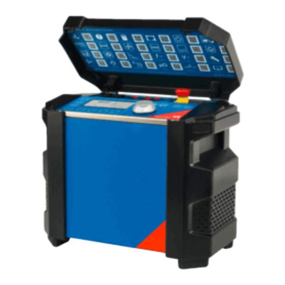
COMPANO 100
Application Area
Cable Impedance Measurements
Keywords
Cable Impedance, k-factor, Line Impedance
Version
v1.0
Document ID
ANS_23003_ENU
Abstract
This application note explains how the impedances and the k-factor of short power cables (up to 5 km) can
be measured with COMPANO 100. Such cables are very common in urban distribution networks and
industrial energy networks.
The results can be used for configuring protection relays, performing load calculations or for network
simulations.
For longer cables or overhead lines, use CPC 100 + CP CU 1.
Advertisement
Table of Contents

Related Manuals for Omicron COMPANO 100


Summary of Contents for Omicron COMPANO 100
- Page 1 Abstract This application note explains how the impedances and the k-factor of short power cables (up to 5 km) can be measured with COMPANO 100. Such cables are very common in urban distribution networks and industrial energy networks. The results can be used for configuring protection relays, performing load calculations or for network simulations.
- Page 2 However, OMICRON does not assume responsibility for any inaccuracies which may be present. OMICRON translates this application note from the source language English into a number of other languages. Any translation of this document is undertaken for local requirements, and in the event of a dispute between the English and a non-English version, the English version of this note shall govern.
-
Page 3: Table Of Contents
Safety Concept ..........................7 Handling of the CP GB1 Grounding Box ..................9 Measurement Method ........................9 Connecting COMPANO 100 and CP GB1 to a power cable ............11 First criterion ..........................12 Second criterion: Estimated open-cable voltage................. 12 Third criterion: Measured open-line voltage ................14 Forth criterion: Injected test current ..................... -
Page 4: Safety Instructions
Before handling the COMPANO 100 in any way, connect them with a solid connection of at least 6 mm2 cross-section to ground. Use the CP GB1 grounding box to connect the COMPANO 100 to short (< 5 km) medium voltage (< 36 kV) power cables only. -
Page 5: Operating The Measurement Setup
(for example when changing connections at the CP GB1 between measurement loops). Use only 10 m (~30 ft) measurement leads supplied by OMICRON to connect COMPANO 100 to CP GB1. Before connecting the CP GB1 with COMPANO 100 or when changing the connection, press the Emergency Stop button. -
Page 6: Disclaimer
Risks arising from overlapping work activities on the same installation need to be evaluated and clarified beforehand. Unauthorized persons must be prevented from accessing and/or activating COMPANO 100, CP GB1 or any of its accessories. Following the instructions provided in this User Manual is also considered part of being in accordance with the regulations. -
Page 7: Introduction
CP GB1’s surge arrestors do. Always use measurement leads with a least 10 m / 30 ft length to connect COMPANO 100 to CP GB1, as shown below. This limits the transients till the CP GB1 surge arrestors react. - Page 8 Distance ≥ 5 m / 15 ft COMPANO I OUT MV Switchgear Cabinets CB GB1 Figure 2: Possibility how to position COMPANO 100 outside the dangerous area. Distance ≥ 5 m / 15 ft MV Switchgear Cabinets I OUT COMPANO CB GB1 Figure 3: Best way to position COMPANO 100 outside the dangerous area.
-
Page 9: Handling Of The Cp Gb1 Grounding Box
This safety concept was type tested and ensures the operators safety in the worst case, namely when the cable is accidentally energized during the measurement. • The voltages on the housing of COMPANO 100 will be limited to a safe level. • The voltages in COMPANO 100 may damage the equipment irreversible, if the is accidentally energized or the cable length or open-loop voltage is far too high. - Page 10 The measurements will be repeated for different current-loops and the single results will be combined to calculate the parameters of different line models as well as the k-factors using a provides Excel Template. © OMICRON 2024 Page 10 of 25...
-
Page 11: Connecting Compano 100 And Cp Gb1 To A Power Cable
/ 30 ft length. For cable impedance testing COMPANO 100 must be connected to a power cable. Due to the fact that the near end of the cable must be disconnected from ground, there is a high danger potential and the risk for persons and test equipment to be exposed to hazardous voltages. -
Page 12: First Criterion
First criterion Note Check if the cable to test has a length with is less than 5 km / 3 For longer lines, the output power of COMPANO 100 miles. might be not sufficient, especially in case of interferences or coupling from parallel systems. - Page 13 Note: If the calculated voltage U exceeds 20 V, the measurement cannot be performed, since the current es t output of COMPANO 100 is not designed for driver higher voltages! If this is the case, please consider the following options: •...
-
Page 14: Third Criterion: Measured Open-Line Voltage
3. Connect the cables of the grounding set used for estimating the open-line voltage (see 3.2 Second criterion: Estimated open-cable voltage.) to the GB1. 4. Connect the other ends of the grounding set to the three phases of the power cable. © OMICRON 2024 Page 14 of 25... -
Page 15: Forth Criterion: Injected Test Current
9. Close the grounding switch again! Note: If the measured voltage exceeds 20 V, the measurement cannot be performed, since the current output of COMPANO 100 is not designed for driver higher voltages! If this is the case, please consider the following options: •... - Page 16 Use measurement leads of at least 10 m / 30 ft length. 2. Position COMPANO 100 outside the danger zone, at least 5 m / 15 ft from the CP GB1. 3. Ground COMPANO 100, using a cable of at least 6 mm² cross-section, close to the position of the operator.
- Page 17 Now you can continue with the actual measurement in the next chapter. • If the current can’t be injected, COMPANO 100 will show an overload indicator. This usually happens if the cable impedance is too high to drive the configured current.
-
Page 18: Cable Impedance Measurements
CP GB1 between measurement loops). Follow the instructions in chapter 3 Connecting COMPANO 100 and CP GB1 to a power cable on page 11 in order to connect the CP CU1 to the power cable under test and check the four criteria. -
Page 19: Perform Measurement
L2 – E Earth / Ground Stud L2-E L3 – E Earth / Ground Stud L3-E L1+L2+L3 – E Bridged L1, L2 and L3 Earth / Ground Stud L123-E Table 2: Required measurement loops © OMICRON 2024 Page 19 of 25... - Page 20 2-7.). If stated, bridge L1, L2 and L3 with the bridge cable. 3. Release the emergency stop button on COMPANO 100 and wait till the device is ready 4. Start the output by pushing the start button.
-
Page 21: Evaluation Of Measurements
Fill the blue fields, including cable length and used measurement frequencies (see Table 1). Open the COMPANO Excel File loader in Windows Start menu: Start → OMICRON COMPANO 100 → COMPANO 100 Excel File Loader Perform the following steps for each of the seven results files (see Table 2). - Page 22 L1-L3) in the cable impedance report. L1-L3 Figure 9: Result file of a single measurement loop ↓ Figure 10: COMPANO Template for calculating the cable impedance Repeat this for the result files of all seven measurement loops. © OMICRON 2024 Page 22 of 25...
-
Page 23: Results
Results The final results can be found on the lower half of the Cable Impedance Measurement Template. Figure 11:Results of the measurements in the COMPANO 100 Cable Impedance Template The Z impedance will be calculated from different measurements. The results in the Z... -
Page 24: List Of Literature
List of literature [1] COMPANO 100 User Manual [2] CP CU1 User Manual © OMICRON 2024 Page 24 of 25... - Page 25 At our support hotline, you can reach well-educated technicians for all of your questions. Make use of our 24/7 hotlines: Americas: +1 713 830-4660 or +1 800-OMICRON Asia-Pacific: +852 3767 5500 Europe / Middle East / Africa: +43 59495 4444 Additionally, you can find the service center or sales partner closest to you at omicronenergy.com.
Need help?
Do you have a question about the COMPANO 100 and is the answer not in the manual?
Questions and answers