Table of Contents
Advertisement
Advertisement
Table of Contents

Subscribe to Our Youtube Channel
Related Manuals for Omicron CT Analyzer


Summary of Contents for Omicron CT Analyzer
- Page 1 CT Analyzer & CT SB2 Getting Started...
- Page 2 Getting Started with CT Analyzer & CT SB2 Manual Version: ENU 1132 03 01 This manual refers to version 4.50 of the CT Analyzer firmware and the CT Analyzer PC Toolset software. © OMICRON electronics GmbH 2016. All rights reserved.
-
Page 3: Safety Symbols
Minor or moderate injury may occur if the appropriate safety instructions are not observed. NOTICE Equipment damage or loss of data possible Related documents The following documents complete the information covered in the Getting Started with CT Analyzer & CT SB2 Manual: Title Description CT Analyzer User Manual Contains information how to use and operate the CT Analyzer as well as safety instructions for working with the CT Analyzer. -
Page 4: Safety Instructions
Before operating the CT Analyzer, read the safety instructions in this User Manual carefully. Do not turn on the CT Analyzer and do not operate the CT Analyzer without understanding the safety information in this manual. If you do not understand some safety instructions, contact OMICRON before proceeding. -
Page 5: Operating The Measurement Setup
► Before putting the CT Analyzer into operation, check the equipment for visible damages. ► Use the CT Analyzer and its accessories only in a technically sound condition and when its use is in accordance with the safety regulations for the specific job site and application. -
Page 6: Power Supply
The CT Analyzer and its accessories may be used only as described in this User Manual. Any other use is not in accordance with the regulations. The manufacturer and the distributor are not liable for damage resulting from improper usage. - Page 7 OMICRON test sets are subject to the EU Waste Electrical and Electronic Equipment Directive 2012/19/EU (WEEE directive). As part of our legal obligations under this legislation, OMICRON offers to take back the test set and ensure that it is disposed of by authorized recycling agents.
- Page 8 Parameters that are guessed by the CT Analyzer are marked by a question mark in the user interface of the CT-Object card prior to the test. To have a parameter guessed by the CT Analyzer, select the ? soft OMICRON...
- Page 9 The manufacturer and the distributor are not liable for damage resulting from improper usage. The user alone assumes all responsibility and risk. Note: The Quick Test function of the CT Analyzer and the CTA Quick Test PC tool cannot be used with the CT SB2 switch box. OMICRON...
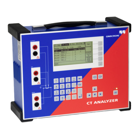
- Page 10 Getting Started with CT Analyzer & CT SB2 Functional components of the CT Analyzer 2.4.1 Overview Figure 2-1 provides an overview of the operating and display elements and the connectors of the CT Analyzer. Output Remote control interface Grounding Display...
-
Page 11: Inputs And Outputs
Generator output. AC: 40V , 5A DC: 120V, 5A (15A peak Measurement input for secondary side of CT, 300V max. Prim Measurement input for primary side of CT, 30V max. Figure 2-2: Inputs and outputs of the CT Analyzer OMICRON... - Page 12 Any other behavior of the status LEDs than described above indicates an error. In this case, switch off the CT Analyzer. Do not touch any part of the test setup until the red LED is off and contact the OMICRON Technical Support (refer to chapter "Support" on page 29).
-
Page 13: Functional Components Of The Ct Sb2
CT ANALYZER bonding connector Measurement input for primary Input and output terminals for connection to side of the CT. the CT Analyzer measurement inputs and generator output. OUT: Generator output for primary winding resistance measurement. A green LED lights up when the output is active. -
Page 14: Setup And Connection
► Before putting the CT Analyzer into operation, check the test set for visible damages. ► When taking the CT Analyzer into operation, make sure that the air slots, the power switch and the power supply plug at the test set are not obstructed and that the test set can be easily disconnected from mains. - Page 15 ► If possible, use the optional CT SB2 switch box for testing multi-ratio CTs. The CT Analyzer then automatically reduces the test voltage in a way that the maximum possible voltage within the measurement setup (i.e., the voltage occurring at the tap combination with the highest ratio) is limited to 200V.
-
Page 16: Setting Up The Ct Analyzer
. Use a ground point as close as possible to the test object. 3. Connect the CT Analyzer to mains using the supplied power cord. Supply the CT Analyzer only from a power outlet that is equipped with protective ground (PE). - Page 17 3. Connect the black socket of CT Analyzer input "Prim" to the grounded side of the CT’s primary circuit and the red socket of this input to the open (ungrounded) side.
- Page 18 Getting Started with CT Analyzer & CT SB2 5. Connect the red "Output" socket and the red socket of input "Sec" of the CT Analyzer to the other (ungrounded) terminal on the secondary side of the CT. Prevent coupling of interferences into the primary circuit (e.g. by disconnecting the utility line, Utility line switching off the breaker, etc).
-
Page 19: Basic Measurement Setup For Multi-Ratio Ct Testing
Basic measurement setup for multi-ratio CT testing Burden For information how to connect the communication link between the CT SB2 and the CT Analyzer, please refer to the CT SB2 User Manual. Figure 3-2: Basic measurement setup for multi-ratio CT testing (6 tap CT, no burden measurement, no... -
Page 20: Mains Power Supply
Connector according to IEC 60320 Mains voltage 100 - 240V / 50/60Hz / 6A Instead of supplying the CT Analyzer from phase-neutral (L1-N, A-N), it may also be supplied from phase-phase (e.g. L1-L2, A-B). However, the nominal voltage must not exceed 240V Mains fuses... -
Page 21: Winding Resistance Measurement Accuracy
• One terminal of the primary side of the CT is connected to PE. • The original measurement cables delivered by OMICRON for the CT Analyzer are used. • The CT under test is a CT with a non-gapped core. -
Page 22: Compact Flash Card Interface
(e.g. running the CT Analyzer PC Toolset software) or to the optional CT SB2 switch box (for multi-ratio CT measurement). As of serial number JHxxxx or newer, the CT Analyzer is equipped with a USB interface and a RS232 interface. -
Page 23: Usb Interface
Technical data of the CT Analyzer 4.7.1 RS232 interface The RS232 interface can be used to connect the CT Analyzer to a computer or to the optional CT SB2 switch box. 9-pole SUB-D connector, male Figure shows outside view onto the pins at the CT Analyzer! -
Page 24: Environmental Conditions
Getting Started with CT Analyzer & CT SB2 Environmental conditions Table 4-11: Environmental conditions Characteristic Rating Operating temperature –10 … +50°C (14 … 122°F) Storage and transportation –25 … +70°C (–13 … 158°F) Max. altitude for operation 2000m Mechanical data... - Page 25 –20 … +70 °C (–4 … 158 °F) Max. altitude for operation 2000m Mechanical data Table 5-3: Mechanical data Characteristic Rating Weight 2.6kg (5.7lbs) without accessories Dimensions W x H x D 285 x 68 x 225mm (11.2 x 2.7 x 8.9") OMICRON...
- Page 26 Getting Started with CT Analyzer & CT SB2 Standards Table 5-4: Standards EMC, safety IEC/EN 61326-1 (industrial electromagnetic environment) FCC subpart B of part 15, class A Safety IEC/EN/UL 61010-1 Other Shock IEC/EN 60068-2-27 (15 g/11 ms, half-sinusoid, 3 shocks in each axis) IEC/EN 60068-2-6 (frequency range 10 Hz…150 Hz, acceleration 2 g...
- Page 27 OMICRON Academy – learn more www.omicronenergy.com/academy Learn more about your product in one of the training courses offered by the OMICRON Academy. OMICRON electronics GmbH, Oberes Ried 1, 6833 Klaus, Austria, +43 59495 OMICRON...
- Page 28 ENU 1132 03 01...
Need help?
Do you have a question about the CT Analyzer and is the answer not in the manual?
Questions and answers