Advertisement
Quick Links
Advertisement

Related Manuals for Omicron MPD 600


Summary of Contents for Omicron MPD 600
- Page 1 MPD 600 ADVANCED PARTIAL DISCHARGE MEASURING SYSTEM Quick Start Guide...
- Page 2 The user is responsible for every application that makes use of an OMICRON product. OMICRON electronics translates this manual from the source language English into a number of other languages. Any translation of this manual is done for local requirements, and in the event of a dispute...
-
Page 3: Setting Up Your System
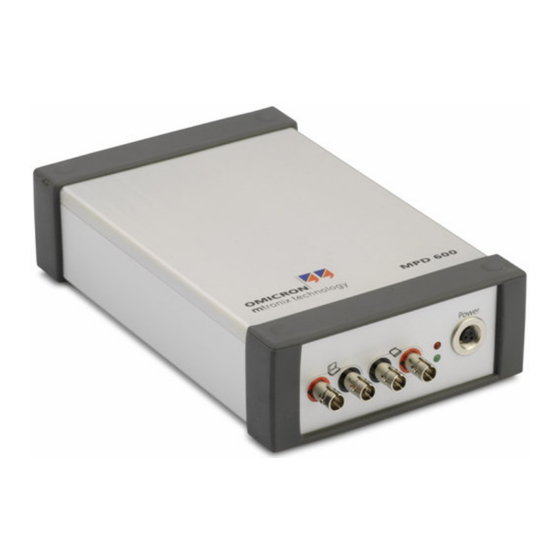
1 Setting up your System Figure 1: MPD 600 advanced partial discharge measuring system with coupling capacitor This quick start guide will lead you step-by-step from setting up the MPD 600 advanced partial discharge (PD) measuring system to performing your first measurement. - Page 4 Figure 3: MPD 600 Acquisition Units (front and rear view) • Connect the MPD 600 Acquisition unit to the fiber optics controller using fiber optical cables. See wiring diagram on next page for details. Please observe that TX (transmit) is always connected to RX (receive) and vice versa.
- Page 5 Please substitute the battery pack with a power supply if desired. Always remember to keep all cables in the signal path as short as possible. The MPD 600 acquisition unit is small and should be placed as close as possible to the coupling capacitor and test object.
- Page 6 Once the computer has started, double-click the mtronix Icon to start the software: Figure 5: mtronix Basic Software The different sections of the MPD 600 window: 1 – Acquisition unit display. The acquisition unit display shows which units have been detected by the software.
-
Page 7: Setting Up The Software
Advanced Partial Discharge Measuring System MPD 600 3 – Control panel. The control panel provides access to all measurement and display options. 4 – Large scope view. The large scope view shows the high-voltage curve(s) of the connected acquisition units, as well as the phase-resolved histogram of the currently selected unit. - Page 8 Advanced Partial Discharge Measuring System MPD 600 • Make sure that the “Input Protection” option is checked. You may uncheck this option for very sensitive measurements but the PD input of the acquisition unit is then somewhat more sensitive to damage by electrical surges.
- Page 9 Advanced Partial Discharge Measuring System MPD 600 We will now perform a calibration of the test object and high voltage supply. Connect the calibrator to the test object. Select a charge of 100pC. Pulses should clearly extend from the background noise as “spikes”. If the noise floor covers PD pulses, select a higher charge on the calibrator (depending on your test object and available charge calibrator you may use another charge level).
Need help?
Do you have a question about the MPD 600 and is the answer not in the manual?
Questions and answers