Table of Contents
Advertisement
Quick Links
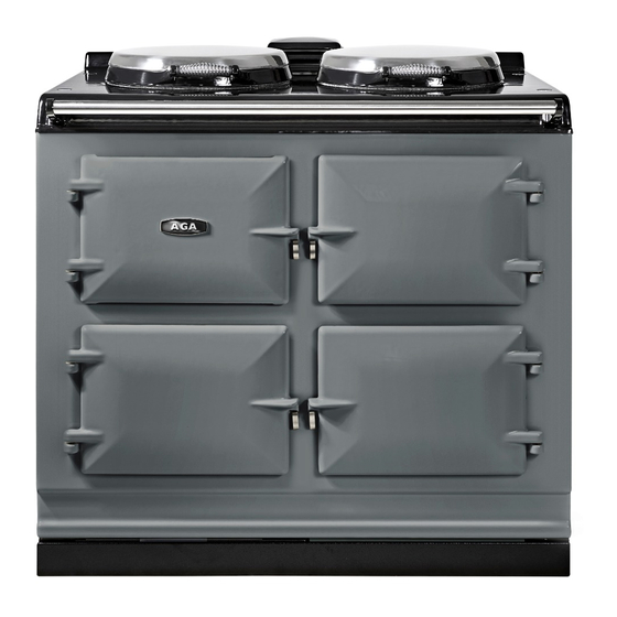
Aga eR7
Field Service Manual USA and Canada
The information detailed in this guide applies to the Aga eR7 electric cooker, at all times the service
technician MUST apply their competencies and ensure the appliance is left safe for continued use,
should the appliance fail any test then engineering judgement must be applied as to whether the
appliance can be left operational.
Page 1 of 34
Advertisement
Table of Contents

Related Manuals for AGA RANGEMASTER eR7


Summary of Contents for AGA RANGEMASTER eR7
- Page 1 Aga eR7 Field Service Manual USA and Canada The information detailed in this guide applies to the Aga eR7 electric cooker, at all times the service technician MUST apply their competencies and ensure the appliance is left safe for continued use, should the appliance fail any test then engineering judgement must be applied as to whether the appliance can be left operational.
-
Page 2: Table Of Contents
Touch control unit and thermocouples: ................... 26 Oven elements: ..........................27 AGA Hotcupboard eR7 150 ........................28 Essential Parts List ..........................28 Wiring schematic. (North America) ...................... 29 AGA Hotcupboard ..........................30 AGA INSULATING LID HINGE ASSEMBLY (Introduced 2005) ..............34 Page 2 of 34... -
Page 3: Product Overview
Product overview The Aga Er7 is an all-electric cooker that replaces the Aga Total Control it offers new enhanced features with everyday radiant heat and has independently controlled hotplates and ovens, features include: Capacitance touch-screen control panel with LED lighting. -
Page 4: Cooking Zones
Cooking zones Below is a picture showing the different cooking zones on the Aga eR7 100. All ovens and both hotplates are independently controllable using the control panel located behind the top left hand control door. Aga eR7 150 The Aga er7 150 has a hotcupboard attached to the parent Aga, the hotcupboard does not use the electronic controls that the eR7 utilises and is supplied either with a warming plate or a single zone induction hob on the top. -
Page 5: The Capacitance Touch Control Panel
The capacitance touch control panel Like the classic Aga cooker design the Aga eR7 has a Boiling plate and a Simmer plate. Each hotplate is individually temperature controlled and pre –programmed within the main PCB Each of the three ovens have their own pre-set temperature settings. When using the roasting and baking ovens, different temperatures can be selected to suit the customer’s needs. -
Page 6: General Information And Power Sharing
The Aga eR7 does not need to be regularly serviced. DO NOT ALTER or MODIFY the appliance. The appliance warranty does not cover commercial use. Please refer to the Aga eR7 cooker installation instructions for specific information regarding appliance dimensions, clearances, electrical requirements and oven venting etc. www.agaliving.com/... -
Page 7: Power Supply Connections
The electric connection must be done by a licensed electrician. The Aga Er7 cooker leaves the factory set up for connection to a power supply, the power cable and standard four (4) prong type 14-50p plug are pre connected at the factory. -
Page 8: Essential Tools
• • Hob support bars - (AE4M280399) The electrical connections on the Aga Er7 must be tightened by the use of a torque screwdriver, please see the table on the next page for the relevant settings. Torque screwdriver settings Torque Setting NM... -
Page 9: Fault Diagnostics Overview
Fault diagnostics overview The Aga Er7 control system is capable of detecting a range of conditions that have been pre- determined as fault conditions .Error codes are generated when an error condition is detected, the code signifies the type of error and the zone(s) affected, the codes are stored in the main PCB and can be reviewed at any time after the error has occurred. -
Page 10: Connecting The Tek Vision Software
Connecting the TEK Vision software The below picture shows how the laptop is connected to the Tek PCB , the USB end fits into the laptop and the other end is connected to the GSM port on the PCB, this connector has a spring type clip on the end which will need to be pushed to release and remove. -
Page 11: Fault Diagnostics
COMS cable and the sockets on the PCB and facia. Should the customer report an error code on their eR7 AGA and you are required to visit site to investigate, then the Tek vision software must be connected using the connection key and your laptop. -
Page 12: Tek Vision Opening Screen With Laptop Connected
TEK Vision opening screen with laptop connected When using the Tek Vision software ensure the cooker power on /off button is on. Below is a step by step guide to navigating the tek vision software. With the cookers PCB connected to your laptop using the appropriate connection key, double click the Tek Vision icon, Tek Vision will open and the below will be shown on your laptop screen , the default screen is the set up screen. -
Page 13: Tek Vision Diagnostics Screen With No Errors Present
TEK Vision diagnostics screen with no errors present Below is the temperature tab which shows the cooker working in real time and you will see that each zone shows the current temperatures recorded by the internal thermocouples and also in red it shows if any errors are currently present. -
Page 14: Tek Vision Diagnostics Screen With Errors Present
You will see above the fault count pop up box gives you the option to save the fault count to file. This must be saved and kept safe on every occasion a fault is found. This may be required as any fault diagnostic discussion with AGA. Page 14 of 34... - Page 15 To save the file, click the yes button and follow the instructions to save the file directly onto your laptop as shown below. Once the fault is cleared and with all zones on you should be able to see the below sceen on the laptop showing that all zones are turned on and the cooker is heating up normally and power sharing, it also gives information on,thermocouple temperatures,power being used and the user panel temperature.
-
Page 16: Explanation Of Error Codes And Advice What Action To Take
Explanation of error codes and advice what action to take Error Code Zone Affected Description Action Reset and log, if recurring then PCB may be Com WD Fault required Check communication cable connections and Com WD Fault continuity of cable, reconnect, reset and test Not used Not used Reset and log, If recurring then PCB may be... - Page 17 *Important Note* Please refer to the notes below to assist you with your diagnosis of any error codes recorded. 007: Error 7 will occur if the user panel PCB is unable to process thermocouple measurements requiring the user panel to be replaced. 010 - 014: Full power time out - A full power time out is a safety feature implemented to show the cooking zone is taking too long to reach it’s expected temperature.
-
Page 18: To Reset The Pcb After A Fault Condition
To reset the PCB after a fault condition Press and hold the reset button located on the front left hand side of the PCB. Customers should not be instructed on how to reset the PCB. The main PCB screen will first display “clearing locks” it’s important to keep pressing the reset button until the screen displays “system reset.”... -
Page 19: The Logging Screen Tab
The logging screen tab The TEK Vision software has an in built data logger, which gives information on all temperatures within the various zones, % of power the various channels are receiving and any fault codes that appear, the log updates around every 5 seconds, as soon as the Tek vision software is opened the system starts to log, if the system has to be reset the log will restart when this has been carried out. -
Page 20: The Graph Screen Tab
The graph screen tab The graph screen tab gives temperature information for all of the cooking zones and the user panel by using a graph, each zone has a different colour and time and temperature is recorded, individual zones can be recorded on their own if required. Page 20 of 34... -
Page 21: Engineer's Diagnostic Handset - (Ae4M280323)
Using the engineers hand set: A special handset is supplied to Aga Er7 engineers, as a diagnostic tool. This can be recognised by its orange coloured trim. A red handset is available for the USA this will display the temperatures in... -
Page 22: Removal And Replacement Of Major Components
Removal and replacement of major components When replacing components ensure that the mains power supply is isolated. Main PCB: Remove the magnetic plinth at the base of the cooker, Remove 2 screws either side of PCB tray. Pull the PCB tray out from the cooker. When the PCB tray is pulled out this will give access to the main electrical cable terminal block, element connection terminal block (these are labelled and colour coded for easy identification), external vent fan connection and vent fan speed adjuster , communication cable connection and... -
Page 23: Boiling Plate And Simmer Plate
The thermocouple is attached to the element using the bracket shown, it is important when replacing the thermocouple to locate the tip in the right position on the element The duplex thermocouples used in the Aga eR7 are all of the same type for all cooking zones. Page 23 of 34... -
Page 24: Customers Touch Control
Customers Touch Control: To gain access to the TCU whether to exchange or to gain access to the thermocouple connections the cooker front plate will need to be removed, to do this the top plate will need to be propped, the front plate is secured by three studs/nuts along its top length, remove the nuts and pull the top plate forward and lifted away from the cooker base plate leaving the tunnels and control panel secured to the main cooker chassis. -
Page 25: Oven Doors
Oven doors: Remember when refitting the oven doors to fit in the right configuration. The Baking and Simmer oven doors have a gap in the door rope seal whereas the Roasting oven has no gap as per the diagram below. Page 25 of 34... -
Page 26: Touch Control Unit And Thermocouples
Touch control unit and thermocouples: The TCU is attached to the main chassis by 4 screws, remove the screws to either exchange or gain access to the rear of the panel, REMEMBER to support the TCU when doing this. The thermocouples and the communications cable are all connected to the rear of the TCU. The thermocouples are connected to the TCU in a certain order, it is important when either replacing the TCU or a thermocouple, that the thermocouples are replaced in their correct position. -
Page 27: Oven Elements
Oven elements: The oven elements in the Aga Er7 are all rated at 2.5 kw (2500 watts) so they all have the same part number, the roasting and baking oven have two elements located in the roof and base of the oven... -
Page 28: Aga Hotcupboard Er7 150
It is supplied fully assembled and electrically tested. Unlike the situation with a heat store Aga, the hot-cupboard does not need to be warm at all times. The owner chooses when they want the unit heated, simply by operating a push-button switch. -
Page 29: Wiring Schematic. (North America)
Wiring schematic. (North America) Page 29 of 34... -
Page 30: Aga Hotcupboard
AGA Hotcupboard DESN 517488 Page 30 of 34... - Page 31 Page 31 of 34...
- Page 32 Page 32 of 34...
- Page 33 Page 33 of 34...
-
Page 34: Aga Insulating Lid Hinge Assembly (Introduced 2005)
Open and close the lids a few times to check the adjustable bearings are positively locked in and the lids are sitting evenly With AGA Rangemaster’s policy of continuous product improvement, the Company reserves the right to change specifications and make modifications to the appliances described and illustrated at any time.
Need help?
Do you have a question about the RANGEMASTER eR7 and is the answer not in the manual?
Questions and answers