AGA RANGEMASTER R7 Electric Field Service Manual
Hide thumbs
Also See for RANGEMASTER R7 Electric:
- User's manual & installation instructions (48 pages) ,
- Manual (15 pages) ,
- Owner's manual (12 pages)
Table of Contents
Advertisement
Quick Links
Aga R7 Electric
Field Service Manual USA & CANADA
The information detailed in this guide applies to the Aga Dual Control electric cooker, at all times the
service technician MUST apply their competencies and ensure the appliance is left safe for continued
use, should the appliance fail any test then engineering judgement must be applied as to whether
the appliance can be left operational.
Page 1 of 26
Advertisement
Table of Contents

Related Manuals for AGA RANGEMASTER R7 Electric


Summary of Contents for AGA RANGEMASTER R7 Electric
- Page 1 Aga R7 Electric Field Service Manual USA & CANADA The information detailed in this guide applies to the Aga Dual Control electric cooker, at all times the service technician MUST apply their competencies and ensure the appliance is left safe for continued use, should the appliance fail any test then engineering judgement must be applied as to whether the appliance can be left operational.
-
Page 2: Table Of Contents
Oven thermocouple, oven overheat thermostat location..............18 Oven doors: ............................19 AGA Hotcupboard R7 150 ........................20 Essential Parts List..........................21 Aga R7 100 USA / CANADA Wiring diagram..................22 AGA INSULATING LID HINGE ASSEMBLY (Introduced 2005) ..............26 Page 2 of 26... -
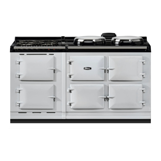
Page 3: Product Overview
Product overview The AGA R7 allows the user to operate the cooker as a traditional heat storage AGA, with the ovens on all the time whilst the hotplates can be turned on or off: • The Boiling plate 340°c (644°F) and the Simmer plate 240° (464°F) are controlled by mechanical thermostats to reach their target temperatures •... -
Page 4: Cooking Zones
Cooking zones Below is a picture showing the different cooking zones on the Aga R7. The hotplates are independently controllable using the control knobs located behind the top left hand control door. In the USA / Canada the simmering oven is called the slow cook oven. -
Page 5: The User Control Panel
The User Control Panel The Aga R7 has been designed so that it is simple to use. There is one control dial to operate the hot plates, and one control dial to operate the Roasting, Baking and Simmering Ovens and on the 5 oven R7 150 model there is one button to operate the hot cupboard. -
Page 6: The User Control Panel Symbols For The Ovens
The User control panel symbols for the ovens. Normal – for everyday use, maintains the ovens at a temperature suitable for roasting, baking and simmering in the respective ovens. 446 degrees F ( 230 degrees C ) Low – for reduced temperature cooking (50ºF lower than normal). To achieve the lower cooking temperature from normal, allow 2½... -
Page 7: Power Supply Connections
Power supply connections. The Aga R7 range must be supplied with a 240v, 60Hz power supply and connected to an individual properly grounded branch circuit protected by a circuit breaker, at 240volts it has a maximum load of 30amps .Electric hook up must be done by a licensed electrician .The unit must be installed according to regional codes, or in the absence of codes, the National Electrical Code. -
Page 8: Essential Tools
• • Hob support bars - (AE4M280399) The electrical connections on the Aga R7 must be tightened by the use of a torque screwdriver, please see the table on the next page for the relevant settings. Page 8 of 26... -
Page 9: Torque Screwdriver Settings
Boiling plate, Simmering plate or both. In each of the hotplates there is powerful heating elements. The Hotspot and Simmer spot elements are similar to the units used on the AGA eR7, but now consist of three internal single circuit elements rated at 2100W , 200W , 200W giving a factory selectable wattage of 2500W or 2300W. -
Page 10: How The Ovens Work
The ovens are standard radiant heat ovens the heat source is a 1.75kw element, they work like a standard heat store Aga, and they can also be set to a low energy setting, which will reduce all of the oven temperatures of the AGA R7 cooker. -
Page 11: To Gain Access To The Main Terminal Block And Oven Pcb
To gain access to the main terminal block and Oven PCB. Remove the bottom plinth at the base of the cooker, remove the screw on the right hand side of the tray and slide out the terminal block plate. This will then give you access to the main terminal block, from here we can check that the appliance is safely isolated from the electrical supply and start to carry out electrical fault diagnosis. -
Page 12: Oven Temperature Pcb
Oven Temperature PCB Thermocouple connection Note: Check for correct polarity Control panel wiring loom Page 12 of 26... -
Page 13: Removal And Replacement Of Major Components
Removal and replacement of major components Oven heating element: To gain access and to remove the oven element, open the baking oven door and remove the two baffles in the roof of the oven, the element support plate will now be visible. Slide out and remove baking oven baffle Remove baking oven deflector plate. -
Page 14: Removal And Replacement Of Major Components
Removal and replacement of major components Oven heating element: To gain access to the oven heating element remove control knobs and glass fascia by removing the 4 chrome caps and screws. Disconnect the wires from element terminal block, remove the blanking plug and the loose insulation from the conduit. -
Page 15: Boiling Plate And Simmer Plate
Working from inside the baking oven, slide out the baffle plates, then using a 4mm allen key, slacken but do not remove the rear screw from the element support plate, which forms part of the oven roof. Remove the other two screws and lower the plate and element as shown in Fig 2. It can be helpful to use a wooden block or something similar to temporarily support the assembly ( Figs 5 &... -
Page 16: Front Plate
Front Plate: To remove the front plate, remove the cooker doors and store safely, then undo the 3 securing nuts sited along the top length of the front plate, pull the front plate forwards and lift away from the base of the cooker, replace in reverse order. -
Page 17: To Gain Access To The Thermostats And Overheat Thermostats
To gain access to the thermostats and overheat thermostats The control panel glass is attached to the main chassis by 4 screws. Remove the chrome caps and the screws to gain access to the rear of the panel. Remove the ribbon connector attached to the oven selector PCB and store the glass panel in a safe place. -
Page 18: Oven Thermocouple, Oven Overheat Thermostat Location
Oven thermocouple, oven overheat thermostat location. The oven thermocouple and overheat thermostat phials are mounted in the roof of the roast oven, they pass through a short guide tube and fix into clips on a bracket. When removing / replacing a thermocouple / overheat thermostat remove the phial location bracket (3 nuts), unclip the phial and carefully pull through from the where the controls are located, replace in reverse order. -
Page 19: Oven Doors
Oven doors: Remember when refitting the oven doors to fit in the right configuration. The baking and simmer oven doors have a gap in the door rope seal whereas the roasting oven has no gap, the diagram below shows the configuration of the doors Page 19 of 26... -
Page 20: Aga Hotcupboard R7 150
It is supplied fully assembled and electrically tested. Unlike the situation with a heat store Aga, the hot-cupboard does not need to be warm at all times. The owner chooses when they want the unit heated, simply by operating a push-button switch. -
Page 21: Essential Parts List
Essential Parts List. • Oven element replacement kit AE9M231466 • Oven thermocouple AE4M232194 Oven overheat cut / out AE4M231334 • • Boiling plate thermostat AE4M231328 • Boiling plate overheat cut / out AE4M231332 Simmer plate thermostat AE4M231329 • • Simmer plate overheat cut /out AE4M231333 •... -
Page 22: Aga R7 100 Usa / Canada Wiring Diagram
Aga R7 100 USA / CANADA Wiring diagram. Page 22 of 26... - Page 23 Page 23 of 26...
- Page 24 Page 24 of 26...
- Page 25 Page 25 of 26...
-
Page 26: Aga Insulating Lid Hinge Assembly (Introduced 2005)
Open and close the lids a few times to check the adjustable bearings are positively locked in and the lids are sitting evenly With AGA Rangemaster’s policy of continuous product improvement, the Company reserves the right to change specifications and make modifications to the appliances described and illustrated at any time.
Need help?
Do you have a question about the RANGEMASTER R7 Electric and is the answer not in the manual?
Questions and answers