Table of Contents
Advertisement
Quick Links
Download this manual
See also:
Owner's Manual
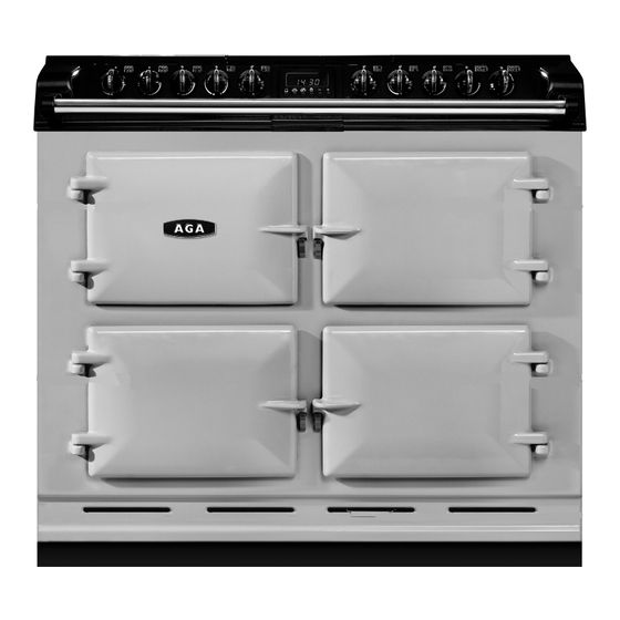
AGA SIX-FOUR DC6 (FFD)
NATURAL GAS
User Guide &
Installation Instructions
CAUTION: THIS UNIT IS HEAVY, PROPER EQUIPMENT AND ADEQUATE MANPOWER MUST BE USED IN MOVING THE
RANGE TO AVOID DAMAGE TO THE UNIT OR THE FLOOR.
REMEMBER, when replacing a part on this appliance, use only spare parts that you can be assured conform to the safety and
performance specification that we require.
DO NOT use reconditioned or copy parts that have not been clearly authorised by AGA.
PLEASE READ THESE INSTRUCTIONS BEFORE USING THIS APPLIANCE
AND KEEP IN A SAFE PLACE FOR FUTURE REFERENCE.
For use in GB & IE
08/17 EINS 517120
Advertisement
Table of Contents

Related Manuals for AGA SIX-FOUR DC6 FFD


Summary of Contents for AGA SIX-FOUR DC6 FFD
-
Page 1: Installation Instructions
REMEMBER, when replacing a part on this appliance, use only spare parts that you can be assured conform to the safety and performance specification that we require. DO NOT use reconditioned or copy parts that have not been clearly authorised by AGA. PLEASE READ THESE INSTRUCTIONS BEFORE USING THIS APPLIANCE AND KEEP IN A SAFE PLACE FOR FUTURE REFERENCE. -
Page 3: Table Of Contents
Cooker hoods and oven venting Levelling Wok burner Cooker stability The ovens Assembly of burners Grill Pan supports Simmering oven 13. Circuit diagram 6 button clock 14. Technical data Oven shelves 15. Servicing the Aga 6-4 Cooking guide 16. Servicing Cleaning & caring... -
Page 5: Health And Safety
Health and safety Consumer Protection The appliance may contain some of the materials that are indicated below. It is the Users/Installers responsibility to As a responsible manufacturer, we take care to make sure ensure that the necessary personal protective clothing that our products are designed and constructed to meet the is worn when handling where applicable, the pertinent required safety standards when properly installed and used. - Page 6 Deep Fat Frying If You Smell Gas • Use a deep pan, large enough to completely cover the • DO NOT turn electric switches on or off appropriate heating area. • DO NOT smoke NEVER fill the pan more than one-third full of fat or •...
-
Page 7: Introduction
The AGA Six-Four takes all the flexibility and convenience of an AGA heat-storage cooker and fuses it with the instant response of a conventional range cooker. Refer to the diagram in the Overview chapter to familiarise yourself with the product and refer to the relevant sections for the ovens, plates, controls etc. -
Page 8: Overview
Overview Fig. 3.1 DESN 517169 Fig. 3.2 DESN 517169 Cooker overview Fig. 3.1 Gas hob overview Fig. 3.2 Your appliance is supplied with the following accessories: • 5 oven shelves Grill compartment Gas burner knobs Lower fan oven Grill knob •... -
Page 9: Control Panel
• 3 spillage wells (cast) cause concern. • 6 burner caps The AGA appliance will emit an odour for a short while, this is simply due to the protective oil we put on the hotplate and • 6 burner heads ovens burning off. -
Page 10: Controls
Controls Hobs The gas hob control can only be rotated anti-clockwise from the OFF position. The grill control needs to be pushed in before turning in either direction. Large Flame - High Setting • Clockwise both elements on • Anti-clockwise middle element only The oven control which DO NOT need to be pushed in, can only be rotated clockwise from the off position. -
Page 11: Pan Supports
Griddle plate The griddle plate is designed for use ONLY on your AGA DC6 Natural Gas appliance. It MUST only be used on the right hand rapid burners. -
Page 12: General Advice
Rapid and semi-rapid burner DESN 513513 Warm up times As the AGA works on the principle of storing heat, time is Fig. 3.6 required to gather that heat from the electric elements to saturate the castings. We recommend to allow an hour heat up time. -
Page 13: Wok Burner
SOME SAFETY POINTS Fig. 3.8 Fig. 3.9 Make sure that the flames are under the pans. Using a lid will help the contents boil more quickly (Fig. 3.8). Large pans should be spaced well apart. ArtNo.311-0002 Pan with rim Pans and kettles with concave bases or down-turned base rims should not be used (Fig. -
Page 14: The Ovens
The ovens Grill THE GRILL COMPARTMENT DOOR MUST BE KEPT OPEN The shelves are designed to be non-tilt. WHEN THE GRILL IS ON. Shelf positions are counted from the bottom. CAUTION: Accessible parts may be hot when the grill is in Put dishes in the centre of the shelf. -
Page 15: Simmering Oven
This is used for long, slow cooking over 6-8 hours, keeping the better, we recommend one hour. food warm and warming plates for short periods. • For best results use the AGA stainless steel cookware. EXTRA CARE MUST BE TAKEN WHEN WARMING BONE CHINA - USE THE LOWEST SETTING. -
Page 16: Button Clock
6 button clock The clock must be set to the time of day before the oven Fig. 4.1 will work. Using the clock ArtNo.302-0002 - 6BC annotated You can use the timer (Fig. 4.1) to turn the oven(s) on and off. The clock must be set to the time of day before the oven(s) will work. - Page 17 Setting a cook duration Fig. 4.7 Fig. 4.8 Press and hold the [ ] button and set the required ‘cook period’ by pressing the [+] button (or [–] button) (Fig. 4.6). The clock will now control the cook period of your oven(s). The [ ] symbol and [AUTO] will be displayed.
- Page 18 Beeper tone adjustment. Fig. 4.14 The beeper tone can be adjusted to three different levels. Whilst in the time of day mode, press and hold the [-] button for a period until the display shows the Tone Bars (Fig. 4.14). ArtNo.302-0002 - 6BC annotated Release the [-] button and immediately press again, this will adjust the tone down by a bar.
-
Page 19: Oven Shelves
Oven shelves Fitting and removal of shelves These shelves are designed to slide out Note: Shelf slides out to stop position. Fig. 5.1 Fig. 5.2 SHELF STOP AND ANTI TILT BRACKET STOP ON SHELF MUST PROJECT UPWARDS DESN 511867 DESN 511866 Grill Shelf Fig. -
Page 20: Cooking Guide
Cooking guide Cooking hints Fanned ovens Refer to the overview chapter • Both ovens must be pre-heated until the light • The lower oven has a fan, which means the air is extinguishes. circulated to create an even temperature throughout the oven. - Page 21 Fanned oven - Cooking table Food Setting ºC Shelf position Approximate cooking time Fish Whole Fish e.g. trout, mackerel 25 - 30 mins depending on size Portions 20 - 25 mins depending on thickness Salmon (2.7kg) 140-150 15 - 18 mins per 450g Roasting Meat Beef 170-180...
- Page 22 Cakes & Biscuits Shortbread 140 - 150 1 1/4 - 1 1/2 hrs Very Rich Fruit Cake 120 - 130 3 - 4 hrs Rich Fruit Cake 4 - 41/2 hrs Small Cakes 170 - 180 20 - 25 mins Scones 200 - 210 10 - 15 mins...
-
Page 23: Cleaning & Caring
Enamelled top and front plate The easiest way to clean the AGA top plate and front plate is to mop up spills as they happen. VEA approved AGA Enamel Cleaner can be purchased from www.agacookshop.co.uk. - Page 24 Gas hotplate Fig. 7.1 If spillage does occur on a burner cap or pan support, move pan to another burner and when cool, clean in hot soapy water. After cleaning, be sure all parts are dry. When fitting the burner cap and burner head, make sure that the hole in the burner head is correctly located over the ignition electrode (see Fig.
- Page 25 A wipe with a damp cloth should be sufficient. TIP: Clean your appliance regularly. Preferably every time you use it. IMPORTANT: AGA recommend Vitreous Enamel Association approved cleaners for cleaning the vitreous enamelled surfaces of this product. Accessories...
-
Page 26: Stainless Steel
Vitreous Enamel Part Recommended Cleaning Method • Door liners • Fan ovens and simmering oven • Front of cooker Clean with a damp cloth and hot soapy water. Stubborn stains can be removed with mild cream, paste all sides or liquid cleaners, or by gently rubbing with a well moistened pads •... -
Page 27: Installation Instructions
REMEMBER, when replacing a part on this appliance, use only spare parts that you can be assured conform to the safety and performance specification that we require. DO NOT use reconditioned or copy parts that have not been clearly authorised by AGA. PLEASE READ THESE INSTRUCTIONS BEFORE USING THIS APPLIANCE... -
Page 28: Installation Introduction
• It should be in accordance also with any relevant pipework passing at the rear. requirements of the Gas Region and Local Authority. • NOTE! THE MAIN AGA COOKER IS DELIVERED EX- • In your own interest, and that of safety to comply WORKS, UNASSEMBLED. -
Page 29: Location
NOTE: It is advisable that the supply cable is routed away If the AGA is to be installed in a brick recess, then the from any hot surfaces i.e. hot water/flue pipes. minimum clearance should be increased by at least 10 mm, to In the interest of safety, due consideration must be given to allow for the walls not being square. - Page 30 10 mm beyond the figures quote above. This allows safe margin to take into account the natural dimensional variations found in major castings in particular the width across an appliance recess could be critical. APPLIANCE WEIGHT Model: AGA Six-Four - 245 kg GAS CONNECTION - AGA 6-4 ONLY Rp1/2 (1/2” BSP MALE)
-
Page 31: Electrical Connection
11. Electrical connection The isolator should not be positioned immediately Electrical connections are located at the back of the above the Module cooker, but must be sited within 2 appliance. metres of the appliance. Refer to Fig. 11.1 and Fig. 11.2 and for wiring connection to Single Phase Connection the appliance. - Page 32 Fig. 11.2 Three phase connection Minimum 2.5 mm² and must comply with the latest editions of the local and national wiring regulations DESN 513371 Remove cover (4 screws) to gain access to the mains terminal DESN 513373 A...
-
Page 33: Installation Sequence And Procedure
12. Installation sequence and procedure Gas connection CAUTION: ENSURE THAT THE APPLIANCE IS ISOLATED FROM ELECTRIC SUPPLY The appliance can be installed with an approved flexible connection. Supply piping SHOULD NOT be less than 3/8 I/D. Connection is made to the R1/2 (1/2”BSP) female threaded fitting located just below the hotplate level on the rear left-hand side of the appliance. - Page 34 Fig. 12.1 DESN 517171 Fig. 12.2 POSITION OF GAS BAYONET ON WALL (locate in shaded areas) LOCATION AREA BAYONET FITTING 135 mm ⁄ ”) 415 mm ⁄ ”) DESN 517564...
-
Page 35: Levelling
The appliance is fitted with mobility rollers, two at the rear and two at the front. The AGA 6-4 is designed to stand on a flat and level surface, however, any unevenness may be overcome by adjusting the four levelling feet, one at each corner of the base plate. - Page 36 Fitting of hotplate casting and pan Fig. 12.5 supports Hotplate casting Attach earth cable from centre casting to cooker chassis and locate over burner bodies. Repeat for left-hand and right-hand castings and that the gaskets are fitted where the outer castings overlap centre castings. Ensure that earth cables are attached (Fig.
-
Page 37: Assembly Of Burners
Assembly of burners Fig. 12.8 IMPORTANT: The cast iron pan supports on the appliance are much heavier than those on most gas hotplate cookers, therefore care must be taken when removing or re-fitting them to the hob. It is important that they are lifted from the appliance and not dragged across nearby enamelled parts which would result in Burner cap retaining lugs... -
Page 38: Pan Supports
It is very important for the performance and reliability of the hob that the pan supports are fitted in accordance with the AGA SIX-FOUR SERIES - DC6 OWNERS MANUAL. To help identify the correct location of the pan supports, the centre pan support has been uniquely designed with tab, as shown (Fig. -
Page 39: Circuit Diagram
13. Circuit diagram DESN 517572 The connections shown in the circuit diagram are for single-phase. The ratings are for 230 V 50 Hz. Code Description Code Colour Gas tap ignition switch Blue Spark generator Brown Grill regulator Black Simmer oven thermostat Orange Clock Lower fan oven thermostat... -
Page 40: Technical Data
14. Technical data The data plate is situated in the centre vent slot near the base of the front plate. Natural Gas G20 (Appliance Category I2H) Burner type RAPID RAPID SEMI - RAPID SEMI - RAPID ULTRA - RAPID Maximum heat input 4.5 KW 3.0 KW 3.0 KW... -
Page 41: Servicing The Aga
15. Servicing the Aga 6-4 TO REMOVE HOTPLATE Fig. 15.1 Isolate from electric supply. Remove pan supports and burner caps (Fig. 15.1) Remove burner fixing screws (14) and hotplate fixing nuts (8). Lift off burner fixing rings (6). Lift off hotplate castings in the following order: left hand, right hand and centre (Fig. - Page 42 TO REMOVE FACIA CASTINGS Fig. 15.4 Isolate from electric supply. Proceed as ‘TO REMOVE HOTPLATE CASTINGS’. Pull off control knobs. Remove control panel fixing screws (4 per casting) (Fig. 15.4). When removing the screws support the casting. NOTE: When removing the castings, the oven indicator neons require disconnecting from the facia, hold the cables at their entry into the neon twist and pull, this will disengage the neon assembly.
- Page 43 TO REMOVE GAS TAPS/IGNITION SWITCHES Fig. 15.7 Isolate from electric and gas supply. Proceed as ‘TO REMOVE HOTPLATE’. Proceed as ‘TO REMOVE FACIA’ . Disconnect gas rail feed pipe (19mm nut) (Fig. 15.9) and (Fig. 15.10). Disconnect all gas connections to taps (5 nuts - 13mm, 14mm &...
- Page 44 TO REMOVE GRILL REGULATOR Fig. 15.11 Isolate from electric supply. Proceed as ‘TO REMOVE FACIA CASTINGS’ . Remove two screws securing control to control mounting panel. Withdraw control and cables taking care not to strain the cables. Disconnect cables from the control. NOTE: Take care to identify terminations.
- Page 45 TO REMOVE ELECTRODE Fig. 15.14 (LEFT HAND BURNER) (Fig. 15.14) Isolate from electrical supply. Proceed as ‘TO REMOVE HOTPLATE’ . Proceed as ‘TO REMOVE SPARK GENERATOR’ . Disconnect the left hand burner pipe (13mm) and the inner burner pipe (13mm) using the special spanner. Remove the burner and burner fixing plate, by unscrewing the (4) screws holding the burner mounting plate in place.
- Page 46 TO REMOVE ELEMENTS (SIMMERING OVEN) Isolate from electrical supply. Remove oven base panel (1) screw at the rear of the oven. Lift out base panel. Remove oven element fixing screws (2) at the rear of the oven and flex elements to remove from location bracket, pull forwards to expose terminal connections.
-
Page 47: Servicing
Aga engineer. Approved Aga engineers have been factory trained and always use genuine Aga spares • In the event of requiring maintenance, please call AGA Service or your authorised distributor. • Your appliance MUST only be serviced by a qualified engineer from AGA tor an authorised distributor. - Page 48 For further advice or information contact your local AGA Specialist. With AGA Rangemaster’s policy of continuous product improvement, the Company reserves the right to change specifications and make modifications to the appliances described and illustrated at any time. Manufactured By...
Need help?
Do you have a question about the SIX-FOUR DC6 FFD and is the answer not in the manual?
Questions and answers