Advertisement

Quick Links

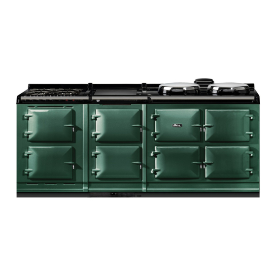
Model No's: R7 100-3 and R7 150-5
REMEMBER, when replacing a part on this appliance, use only spare parts that you can be assured conform to the safety and
DO NOT use reconditioned or copy parts that have not been clearly authorised by AGA.
User Guide &
Installation Instructions
performance specification that we require.
PLEASE READ THESE INSTRUCTIONS BEFORE USING THIS APPLIANCE
AND KEEP IN A SAFE PLACE FOR FUTURE REFERENCE.
For use in USA & CAN
LPRT 517933
04/22 EINS 517934

Advertisement

Table of Contents
loading
Need help?

Need help?

Do you have a question about the R7 100-3 and is the answer not in the manual?

Questions and answers

Subscribe to Our Youtube Channel

Summary of Contents for AGA R7 100-3

  • Page 1 REMEMBER, when replacing a part on this appliance, use only spare parts that you can be assured conform to the safety and performance specification that we require. DO NOT use reconditioned or copy parts that have not been clearly authorised by AGA. PLEASE READ THESE INSTRUCTIONS BEFORE USING THIS APPLIANCE PLEASE READ THESE INSTRUCTIONS BEFORE USING THIS APPLIANCE AND KEEP IN A SAFE PLACE FOR FUTURE REFERENCE.
  • Page 2 Make a note of your AGA R7 Serial Number when it is being installed. The serial number can be found behind the magnetic plinth cover. My AGA Details: Serial No: AGA Service No: Date of Installation: Data badge located behind removable...
  • Page 3: Table Of Contents

    Overview 14. Clearances AGA R7 100 AGA R7 100 AGA R7 150 AGA R7 150 How to use your AGA R7 15. Power Supply connections Getting to know your AGA AGA Hotcupboard connections Oven Controls 16. Mains Supply Location Hotplate Controls...
  • Page 4: Product Safety

    Product Safety Meaning / Description Symbol Signification / Description WARNING / CAUTION AVERTISSEMENT An appropriate safety instruction Une consigne de sécurité appropriée should be followed or caution to a doivent être suivies ou garde d’un potential hazard exists. danger potentiel exists. TENSION DANGEREUSE DANGEROUS VOLTAGE Pour indiquer les dangers...
  • Page 5 Important Safety Instructions INCORRECT USE OF THIS RANGE CAN INCREASE NEVER THE RISK OF FIRE, ELECTRIC SHOCKS OR INJURY Never store items of interest to TO PERSONS. children above the range. PLEASE READ THE FOLLOWING PRECAUTIONS TO Never allow children to climb on, sit REDUCE THESE RISKS.
  • Page 6: Health & Safety

    • PLEASE READ THE ACCOMPANYING WARRANTY. Any • Always make sure your appliance is serviced by a alteration that is not approved by AGA could invalidate qualified technician. the approval of the appliance, operation of the warranty and could also affect your statutory rights.
  • Page 7 • Never cover or restrict the air flow to the controls Do not hang dish towels on the left hand side of the AGA handrail. Doing so will block the air vent. Blocking the air compartment. vent can cause excessive temperature increase to the control •...
  • Page 8: Introduction

    Your new AGA gives you everything you love about the AGA heat storage cooker, but with the added convenience that the two hotplates can be turned on or off, as required.
  • Page 9: Overview

    Simmering oven DESN 517598 Baking Oven The AGA R7 has the traditional cast iron ovens with independently controlled hotplates. A moderate oven for cooking cakes and biscuits, baking fish, lasagne or shepherds pie, plus roasting meat and poultry at a Hotplates medium heat.
  • Page 10: Aga R7 150

    Baking oven Simmering oven DESN 517599 Simmering Oven The AGA R7 150 has the traditional cast iron ovens with independently controlled hotplates. Long, slow cooking in the simmering oven develops flavours and makes the toughest meat tender. It’s large capacity Hotplates means several pans can be stacked here;...
  • Page 11: How To Use Your Aga R7

    Specialist for details. A demonstration will show you how not to put anything such as kettles, saucepans or baking tins to get the best from your new AGA and will give you hints directly onto the insulated covers because they will show any and tips.
  • Page 12: Oven Controls

    The different zones of the AGA R7 cooker are described in the following pages. The traditional AGA heat storage cooker is famous for the gentle warmth it emits; with the AGA R7 you will get warmth only when the cooker is on or warmth, to a lesser degree, when only parts of it are on.
  • Page 13: Hotplate Controls

    The same size as the boiling plate, the simmering plate is also and bakeware slide directly onto the runners, so almost every machined flat to give the best all-over contact with the AGA available square centimetre of space can be used. Food can saucepans, grill pan, frying pan and kettle.
  • Page 14: Operating The Hotcupboard

    ON/OFF • To get the very best performance, we recommend to BUTTON DESN 517225 use the AGA cookware with thick bases and stacking lids. Slow Cooking Oven • Joints of meat and poultry should be brought up to This oven has similar characteristics to the simmering oven heat ideally in the roasting oven for 30 - 45 minutes, and should be utilised in a similar manner.
  • Page 15: General Advice

    This is especially useful for steaming vegetables and keeping sauces warm. • Store the plain shelf out of the AGA. Use it cold in the roasting oven to deflect the heat from the top of the oven, creating a more moderate oven temperature underneath.
  • Page 16: Equipment Supplied With Your Aga Er7

    If you have not already seen a demonstration, ask your AGA Specialist for details. A demonstration will show you how to get the best from your new AGA and will give you hints and tips. You will also see a selection of AGA utensils and accessories being used.
  • Page 17 Toaster Wire Brush AGA Utensils and Accessories This is for toasting bread on the boiling plate. AGA toast is This is for cleaning the renowned for its excellence, crisp on the outside and soft in raw cast iron hotplate To get the very best the centre.
  • Page 18: Fitting And Removing The Oven Shelves

    Fitting and Removing the oven shelves Fitting the shelves for cast iron, roasting, baking and simmering ovens Fig. 7.1 Fig. 7.2 DESN 512403 DESN 512404 Removing the shelves for cast iron, roasting, baking and simmering ovens Fig. 7.3 Fig. 7.4 DESN 512405 DESN 512406...
  • Page 19: Fitting And Removing The Oven Doors

    CAUTION: This unit is heavy, proper equipment and adequate manpower must be used to remove the oven doors. Fitting and removing the oven doors Fitting the Doors Fig. 8.1 Fig. 8.2 DESN 517491 DESN 517489 Removing the Doors Fig. 8.3 Fig.
  • Page 20: Cooking On Your Aga

    As AGA ovens cook by radiated heat from the castings, rather than just hot air, exact temperature conversions are not possible. Look in the AGA cookbook for a recipe. The table below gives a quick guide to using your oven. Remember that oven shelf positions are counted from the top down.
  • Page 21: Cleaning & Caring

    Induction Hob The easiest way to clean the ceramic top on plate and front plate is to mop up spills as they happen. VEA the AGA Induction hob is to mop up spills as soon as they approved AGA Enamel Cleaner can be purchased from www.
  • Page 22: Installation Instructions

    REMEMBER, when replacing a part on this appliance, use only spare parts that you can be assured conform to the safety and performance specification that we require. DO NOT use reconditioned or copy parts that have not been clearly authorised by AGA. PLEASE READ THESE INSTRUCTIONS BEFORE USING THIS APPLIANCE...
  • Page 23: Installation Requirements

    (1005mm) x 29 1/8” (740mm) could be used to check if adequate and in conformance with the regulations. the AGA R7 fully built appliance is able to fit through the Take special care when cutting holes in walls or floor.
  • Page 24: Location

    Surfaces over the top of the range must not be closer than If the AGA is to be installed in a brick recess, then the 30” (760 mm). minimum clearance should be increased by at least ”...
  • Page 25: Clearances

    14. Clearances Fig. 14.1 DESN 516298...
  • Page 26 Make sure that the plinth facia is centrally located and does not overhang the range. Commission the AGA R7, as stated in the relevant Installation Instructions and carry out functional test on each of the features of the AGA R7.
  • Page 27: Aga R7 100

    3/8” (10mm) beyond the figures quoted above. This allows safe margin to take into account the natural dimensional variations found in major castings. In particular the width across the appliance recess could be critical. APPLIANCE WEIGHT (Excludes Packaging) Model: AGA R7 - 979 lb...
  • Page 28: Aga R7 150

    3/8” (10mm) beyond the figures quoted above. This allows safe margin to take into account the natural dimensional variations found in major castings. In particular the width across the appliance recess could be critical. APPLIANCE WEIGHT (Excludes Packaging) Model: AGA R7 - 979 lb Hotcupboard - 243 lb...
  • Page 29: Power Supply Connections

    15. Power Supply connections Electric Shock Hazard The rating plate is located behind the removable plinth. If the supply cord is damaged, it must be replaced by the manufacturer, its service agent or similarly qualified person to avoid a hazard. Electrical Grounding is required on this appliance.
  • Page 30: Aga Hotcupboard Connections

    SIMILARLY QUALIFIED PERSON TO AVOID A HAZARD. A 120v ~ 60 Hz, 5 amp fused electrical supply is required adjacent to the appliance (with the exception of the AGA Hotcupboard with Induction Hob model, please refer to the AGA Induction Hob model instructions for the power supply requirements).
  • Page 31: Mains Supply Location

    16. Mains Supply Location Mains cable routing Fig. 16.1 Mains cable fed from control tray right- hand exit through ducting dependent upon position of supply socket DESN 517783 Fig. 16.2 THE MAINS SUPPLY CONNECT POINT MUST BE WITHIN THE ZONES SHOWN DESN 517784...
  • Page 32: Mains Cable Routing- Aga Hotcupboard

    Mains cable routing- AGA Hotcupboard Fig. 16.3 HOTCUPBOARD POWER SUPPLY Mains cable fed from control tray right- hand exit through ducting dependent upon position of supply socket DESN 517785 Fig. 16.4 THE MAINS SUPPLY CONNECT POINT MUST BE WITHIN THE ZONES SHOWN...
  • Page 33: Hotcupboard Installation

    17. Hotcupboard installation NOTE: The AGA R7 hotcupboard should arrive with the top plate in a jacked up position (except for induction top versions which will arrive with the top fully wound down). This is to allow the complete appliance to be slid onto its plinth when alongside the AGA R7 without the top plates clashing.
  • Page 34 Attach locking screw and jacking screw into plinth. Make sure at this stage that the jacking screw does not protrude beyond outer face of plinth. Ensure locking screw is located into AGA R7 100 plinth but not fully tightened. A gap of approximately 3/8”...
  • Page 35 Run a straight edge along the front of the AGA R7 100 plinth, to ensure the front face of both plinths sit squarely against the straight edge. (Fig. 17.5) When satisfied both plinths sit squarely, jacking screws can be tightened until they just make contact with the AGA R7 100 plinth, and locking screws can now be tightened.
  • Page 36 Fig. 17.7 DESN 516552 The hotcupboard top plate is set 5mm higher than the AGA R7 100 top plate. This is to prevent damage to the enamel during installation. Lower the top plate using the adjusters (Fig. 17.8 and Fig. 17.9).
  • Page 37 Using the stay rod nut adjusting tool, carefully lower the top plate adjusting nuts until the top plate sits at the required height, making sure that the top sits level and matches the height of the AGA R7 100. (Fig. 17.9).
  • Page 38 10. Next the handrail, endcaps and handrail require assembly. Slide the handrail through the handrail brackets. AGA R7 100 HANDRAIL CONNECTION Fig. 17.11 DESN 516880 11. On 5 oven appliances, fit allthread stud into the insert located in the one end of the handrail, then feed the handrail through the bracket (ensuring that the allthread stud is protruding from the right hand side of the hotcupboard handrail) and screw the handrails together.
  • Page 39 14. Finally, fit the plinth facia to the magnets on the front of the plinth, making sure that on 5 oven appliances the right hand side of the module plinth facia sits against the left hand side of the AGA R7 100 plinth facia leaving no gap between.
  • Page 40: Circuit Diagram

    18. Circuit diagram R7 Circuit diagram DESN 517937...
  • Page 41: Aga R7 (Hotcupboard)

    AGA R7 (HOTCUPBOARD) CAUTION: LABEL ALL WIRES PRIOR TO DISCONNECTION. WHEN SERVICING CONTROLS WIRING ERRORS CAN CAUSE IMPROPER AND DANGEROUS OPERATION VERIFY PROPER OPERATION AFTER SERVICING Fig. 18.1 DESN 517488...
  • Page 48 For further advice or information contact your local AGA Specialist With Middleby Residential policy of continuous product improvement, the Company reserves the right to change specifications and make modifications to the appliance described and illustrated at any time. Middleby Residential...

This manual is also suitable for:

R7 150-5R7

Table of Contents