
Subscribe to Our Youtube Channel
Related Manuals for Ametek PHANTOM Miro C321


Summary of Contents for Ametek PHANTOM Miro C321
- Page 1 PHANTOM HIGH-SPEED CAMERA Miro C321/C321J/ N5/JBox 2.0 USER MANUAL When it’s too fast to see, and too important not to. ®...
- Page 2 The contents of this manual are subject to change without notification. PN: ZDOC-64106-MA-0003 Rev 1 Last Updated: May 2022 P H A N T O M H I G H S P E E Vision Research, Inc. | Miro C 321/C 321J/N5/JBox 2.0 Camer a Manual...
-
Page 3: Table Of Contents
When it’s too fast to see, and too important not to. ® Miro C321/C321J/N5/JBox 2.0 User Manual Introduction 2 Connectors 3 Quick Start Guide 4 Battery 5 PCC Phantom Software 6 Signals & Programmable I/O 7 Miro Junction Box 2.0 8 Accessories 9 Support D . - Page 4 VEO 440 & Miro C321J Vision Research, Inc. | Miro C 321/C 321J/N5/JBox 2.0 Camer a Manual...
-
Page 5: Introduction
The Phantom Miro C321, C321J, N5 camera head and Junction Box 2.0 (JBox 2.0) are the building blocks for flexible multiple-camera setups. • Either Stand-alone or with a system for flexibility: The Miro C321 and the N5 camera head with the Miro N-B Base can be used either individually or as part of a multi- camera system. - Page 6 CAMERA CONTROL Phantom cameras come with PCC software for Ethernet-based setup and control. IMAGE STORAGE The C321 and C321J have either 8GB or 16GB of internal memory, and the N5 bases have 8GB of memory. Both cameras and bases have a 240GB internal, non-removable CineFlash to protect data in the event of power loss.
- Page 7 ADDITIONAL FEATURES Set new CSR default: Set a CSR in PCC with customer-selected settings. If settings are not changed, the camera may be powered off and on and the CSR will remain active. Camera must be set at full resolution. Programmable I/O: Assign and define signal parameters for each Programmable I/O port.
- Page 8 Miro C321J Rear View Miro C321 Rear View Miro NJB Top View Miro NB Top View Miro C321 Front View Miro C321J Front View Vision Research, Inc. | Miro C 321/C 321J/N5/JBox 2.0 Camer a Manual...
-
Page 9: Connectors
Fischer connector connects to a Camera Port on a SYSTEM Miro Junction Box (J-Box). REMOTE Fischer connector, Remote port. Recessed push-button turns battery power off BATTERY RESET with use of paper clip or similar object. Fischer connector connects GigE to a control unit ETHERNET computer / laptop for camera control communication. - Page 10 MIRO JUNCTION BOX Vision Research, Inc. | Miro C 321/C 321J/N5/JBox 2.0 Camer a Manual...
- Page 11 BNC connector; closed’ for ready, ‘open’ for not ready; covers all cameras READY connected to this JBox and any JBox up-chain of this one. BNC connector; contact closure causes trigger. BNC connector also TRIGGER accepts TTL pulses (rising / falling edge) for trigger. There is also Trigger on System connector: isolated, <1V deassert, 3 to 24V assert.
-
Page 12: Quick Start Guide
Q U I C K S T A R T G U I D E Vision Research, Inc. | Miro C 321/C 321J/N5/JBox 2.0 Camer a Manual... - Page 13 Phantom cameras are typically controlled with PCC software through a dedicated Ethernet network. PCC is compatible with the 64-bit version of Windows 10 operating systems. The latest version can be downloaded at: www.phantomhighspeed.com/PCC ASSIGNING A Gb CAMERA NETWORK Connecting the camera using Gb Ethernet simply requires the computer to detect the IP address range of Phantom cameras.
- Page 14 POWER ON CAMERA Connect the camera’s dedicated power supply to the Primary DC input or connect via system cable to the Miro JBox. The camera is ready for operation when the red capture light of the Trigger button is illuminated. LAUNCH PCC SOFTWARE Double-click the PCC icon located on the desktop.
- Page 15 Step 1: Enable in PCC: Step 2: Right click the CSR button in the live tab, and select “Set Default CSR” FINE-TUNE SETTINGS After CSR and White Balance are performed, adjust settings, aperture and/or lighting to get a good exposure. A CSR must be performed after any camera settings are adjusted. ‘ARM’...
-
Page 16: Battery
SAVE TO FLASH OR COMPUTER Click the large ‘Save Cine...’ button on the bottom of the ‘Play’ panel. Navigate to the folder where you want to save the Cine file. 2. Enter a file name and from the ‘Save as Type’, select the ‘Cine Raw, .cine’ file format. - Page 17 OPERATION The Miro C cameras and N5 Bases have an internal, non-removable battery designed to provide back-up power to complete an operation and safely save a cine in the event of power loss to the camera or base. The following description of battery operation pertains to both Miro C cameras and the N5 bases.
- Page 18 Capture mode in the event of power loss. This battery operation mode is disabled in the C321J). Trigger mode (Default mode, always selected): This mode protects critical cines and ensures they are saved in the event of DC power loss. The battery activates when the camera is triggered.
- Page 19 The latest version of Phantom PCC software can be downloaded from the Vision Research website: www.phantomhighspeed.com/pcc This manual covers the most commonly used functions. See the ‘PCC Help’ file for details of other settings. PHANTOM CAMERA CONTROL (PCC) APPLICATION OVERVIEW TOOLBAR The ‘Toolbar’...
- Page 20 PHANTOM VIDEO PL AYER (PVP) APPLICATION OVERVIE W PVP can be launched directly from the desktop shortcut or by the ‘Video Out’ toolbar button in PCC. PVP controls the video outputs connected to a video monitor or viewfinder only. PVP provides the ability to view, capture, review, edit and/or save a Cine recorded into the camera’s RAM, to a hard drive or installed Phantom...
- Page 21 SELECTING A CAMER A Select the camera(s) to be controlled listed in the ‘Manager’ tab, or select the camera(s) from the ‘Camera’ pull-down list in the ‘Live’ tab. Once a camera is selected, a ‘Preview’ panel will display to the left of the control tabs showing the current image being captured by the camera.
- Page 22 IMAGE DISPL AY The ‘Zoom Actual Size’ toolbar button resizes the images being displayed in the ‘Preview/ Playback’ panel to their actual size. The ‘Zoom Fit’ toolbar button resizes the images to fit the panel. Images can also be zoomed to a specific magnification ratio by selecting a number from the pull-down list to the right of the ‘Zoom Fit’...
- Page 23 Backup & Restore: Allows for user and factory settings to be saved and recalled from the camera’s memory. Resolution: Sets the camera’s acquisition resolution. There are several options in the pull-down menu. Alternatively, type in a value and the closest valid resolution will be set. Sample Rate: Sets the acquisition frame rate in frames- per-second (fps).
- Page 24 ‘External Sync’ instructs the camera to use one of the following options: • Internal: Camera uses its internal crystal oscillator to drive the frame rate. • External: Camera uses externally supplied frame sync clock pulse to drive the frame rate. This can be used to synchronize two cameras together via F-Sync. •...
- Page 25 RE VIE WING A CINE Once the camera has completed recording a Cine in the camera’s RAM or CineMag, it can be reviewed by selecting it from the ‘Cine’ pull-down selection list in thePCC ‘Play’ tab. A previously saved Cine stored on the computer’s hard drive can be opened using the ‘Open File’...
- Page 26 EDITING AND S AVING A CINE Using the following ‘Video Control’ buttons, locate the first image of the Cine to be saved and click the ‘Mark-In’ button. Locate the last image of the Cine to be saved and click the ‘Mark-Out’ button.
- Page 27 like’ formats (meaning the entire clip will be saved as a single file), while the formats below the line are image formats (meaning each frame of Cine will be saved as a sequence of images). To convert a Cine to a ‘movie-like’ format, select the desired format from the list, navigate to the destination folder, assign a file name to the clip and save.
- Page 28 P R O G R A M M A B L E I / O Vision Research, Inc. | Miro C 321/C 321J/N5/JBox 2.0 Camer a Manual...
- Page 29 Phantom cameras incorporate multiple hardware signals to interface to external devices. Ports on Phantom Miro C321 cameras are programmable. The equipment to access these ports – the MiniBoB, Control BoB, and Junction Box – have ports that are either fixed or programmable.
- Page 30 Programmable I/O incorporates a pulse processor. In addition to assigning different signals, the signal characteristics can be modified to better interface with external devices. In most cases, the signal polarity, filter time, delay and pulse width and edge (rising versus falling) can be set. Setting these characteristics is referred to as ‘Pulse Processor Control.’...
-
Page 31: Signals & Programmable I/O
SUMMARY OF PULSE PROCESSOR SETTINGS Invert: Inverts the signal at the output of the pulse processor. Falling: Selects ‘Falling Edge’ mode for the pulse processor. This mode is only relevant if the ‘Width’ is also specified. When the ‘Falling’ token is present together with ‘Width,’ the pulse processor will generate a negative pulse, triggered from the negative edge of the input signal. - Page 32 hundred ns depending on camera model) negative pulse with the falling edge is used as timing reference. Input signal is active on falling edge. (Default state is high.) TC-Out: A positive polarity time code signal. Normally an unmodulated (dc-shifted) IRIG-B (at RS-232 levels) which follows the internal time base of the camera. It is recommended not to process the ‘TC-Out,’...
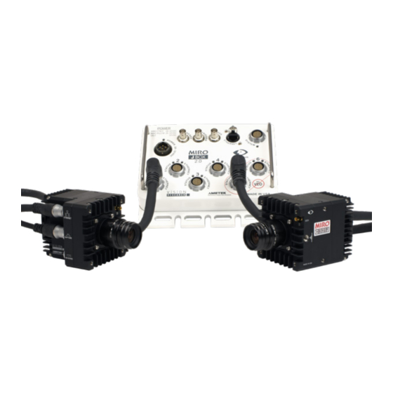
- Page 33 Phantom Miro Junction (JBox) Box MIRO JUNCTION BOX 2.0 (JBOX 2.0) The Miro Junction Box 2.0 (JBox 2.0) is modular and flexible: with six camera ports, it can host up six cameras or dedicate any port to uplink to another JBox in a daisy chain or branch to expand the number of cameras in a configuration.
- Page 34 JBOX 2.0 POWER Max cable length of each camera = 30M Port Port Port Port Port Port Power Option Every JBox requires Req. 20 – 36 VDC of power Miro C Miro C Miro C Miro C Miro C Miro C 280W to power the cameras Miro R...
- Page 35 CAMERA CONTROL The JBox offers 2 methods to control the cameras: Via Gb Ethernet, controlled directly by a computer with PCC or third-party software. 2. Via the System Port and a system cable to access Trigger, IRIG, Strobe, FSYNC, Ready control, and Ethernet.
- Page 36 Event: In PCC, Aux 1 should be set to “Event/Memgate” for all cameras. The Event signal may be input into either the Aux BNC or the System cable. Ready: Aux 2 in PCC should still be set to “Ready”. All cameras connected to the JBox automatically emit a Ready signal when In a Daisy Chain configuration of connected in capture mode.
- Page 37 CONTROL BREAKOUT BOX The Control Breakout Box (Control BoB) offers a sleek and simple way to connect the required signaling to a Junction Box configuration without splicing cables. With ports for IRIG, Ethernet, Ready, Strobe, and FSYNC, the Control BoB is a clean and convenient solution to manage signaling.
- Page 38 MIRO CONTROL BoB Vision Research, Inc. | Miro C 321/C 321J/N5/JBox 2.0 Camer a Manual...
-
Page 39: Miro Junction Box
Trigger (input): When a TTL pulse (rising/ falling edge) is detected, the TRIGGER camera triggers. Ready: Outputs a TTL signal (high) to indicate that all cameras connected to READY the Miro JBox 2.0 are in Capture Mode. Signal can be set to go low at trigger or at the end of recording. - Page 40 CABLES FOR JUNCTION BOX 2.0 System cable, Adapter cable, Short cable to link JBoxes System Cables: Phantom system cables have differential signals for signal integrity over longer distances. They are capable of transporting: Power, Ethernet, and IRIG, FSYNC, Strobe, Ready, Memgate and Event signals. They have a rugged casing and the same Fischer connect at each end, one in a 90 angle and the other in a straight format.
- Page 41 MIRO MINI BREAK OUT BOX The Miro C321 Capture port is compatible with a Phantom Miro Mini Break Out Box (Miro MiniBoB). This connector is not used for the Miro C-Series. TC In (input): Connects to an IRIG receiver to accept a modulated or TC IN unmodulated signal to drive the camera’s frame rate.
- Page 42 Aux 1 (input / output switchable): AUX 1 • STROBE (output): Signal goes low for the duration of each frame’s exposure. • EVENT (input): When the Event signal is active, frames are tagged with an Event marker (as metadata). These events can be searched or referenced during playback.
- Page 43 MOUNTING ACCESSORIES Camera / lens mount: A camera/lens mount makes mounting the camera easier and also provides stability and protection for the lens. Chapter 8: Accessories | 39...
- Page 44 MIRO C321J TOP VIE W MIRO C321J BOT TOM VIE W M E C H A N I C A L D R A W I N Vision Research, Inc. | Miro C 321/C 321J/N5/JBox 2.0 Camer a Manual...
-
Page 45: Support
MIRO C321J RIGHT / LEF T N G S Chapter 9: Suppor t | 41... - Page 46 MIRO C321J FRONT / BACK Vision Research, Inc. | Miro C 321/C 321J/N5/JBox 2.0 Camer a Manual...
- Page 47 MIRO C321 TOP VIE W MIRO C321 BOT TOM VIE W Chapter 9: Suppor t | 4 3...
- Page 48 MIRO C321 RIGHT / LEF T Vision Research, Inc. | Miro C 321/C 321J/N5/JBox 2.0 Camer a Manual...
- Page 49 MIRO C321 FRONT / BACK Chapter 9: Suppor t | 4 5...
- Page 50 71.0 40.0 8.5 X 23.5 35.5 108.0 187.0 N5 & BA SES TOP / BOT TOM / SIDE 140.0 23.5 26.0 83.0 M12x0.5 AIR FLOW 2.50 THRU M3x0.5 - 6H THRU 11.8 163.4 110.0 11.8 163.4 UNLESS OTHERWISE SPECIFIED: PROPRIETARY AND CONFIDENTIAL NAME DATE M12x0.5...
- Page 51 MIRO JUNCTION BOX TOP / SIDE Chapter 9: Suppor t | 47...
- Page 52 Use these schematics to build custom cables at your own risk. Miswired cables can cause serious damage to the camera, which is not covered under warranty. Vision Research recommends only using cables supplied by Vision Research. These pin-out diagrams refer to the connector on the camera or Miro Junction Box body.
- Page 53 MIRO C321 GIGE ETHERNET CONNECTOR Ethernet Port 8-pin Fischer Part # SS 103 A058-130 NOMENCLATURE/FUNCTION ETHRXP / 10/100/1000BASE-T Ethernet Receive (positive) ETHRXN / 10/100/1000BASE-T Ethernet Receive (negative) ETHTXP / 10/100/1000BASE-T Ethernet Transmit (positive) ETHTXN / 10/100/1000BASE-T Ethernet Transmit (negative) MDI2P /10/100/1000BASE-T Media Dependent Interface 2 (positive) MDI2N / 10/100/1000BASE-T Media Dependent Interface 2 (negative) MDI2P / 10/100/1000BASE-T Media Dependent Interface 3 (positive) MDI3N / 100/1000BASE-T Media Dependent Interface 3 (negative)
- Page 54 MIRO C321J NOMENCLATURE/FUNCTION SYSTEM GND / Power Ground CONNECTOR GND / Power Ground System Port GND / Power Ground (for Miro Junction Box) TRIGIN- / Trigger input (neg) from J-Box 27-pin Fischer READYOUT- / Ready / Strobe output (neg) to J-Box Part # SS 105A 102 130 IRIGIN- / IRIG input (negative) from J-Box AUXIN+ / Strobe / Event / Memgate / Fsync input (positive) from...
- Page 55 C321J REMOTE CONNECTOR Remote Port NOMENCLATURE/FUNCTION (for Phantom RCU) 6-pin Fischer PGND / Power Ground Part # SS 103 Z 056 130 +VINBF / The +VDC In (Battery Freed) connector provides +24VDC (Direct Current) positive power to the Phantom camera. RxD1 / RS-232 Receive Data 1 TxD1 / RS-232 Transmit Data 1 UNUSED...
- Page 56 MIRO JBOX 2.0 NOMENCLATURE/FUNCTION SYSTEM GND_A / Signal ground for AUXIN and READYOUT CONNECTOR UNUSED System Port GND_B / Signal ground for IRIGIN and IRIGOUT (for Miro C321J) TRIGIN- / Trigger input (neg) to J-Box 27-pin Fischer READYOUT- / Ready / Strobe output (neg) from J-Box Part # SS 105A 102 130 IRIGIN- / IRIG input (negative) to J-Box AUXIN+ / Strobe / Event / Memgate / Fsync input (positive) to...
- Page 57 MIRO JBOX 2.0 NOMENCLATURE/FUNCTION CAMERA GND / Power Ground CONNECTOR GND / Power Ground Camera Port GND / Power Ground (for Miro C321J) TRIGIN- / Trigger input (neg) to camera 27-pin Fischer READYOUT- / Ready / Strobe output (neg) from camera Part # SS 105A 102 130 IRIGIN- / IRIG input (negative) to camera AUXIN+ / Strobe / Event / Memgate / Fsync input (positive) to camera...
- Page 58 CONTROL NOMENCLATURE/FUNCTION BREAK OUT UNUSED BOX (BoB) GND/ Ground SYSTEM UNUSED CONNECTOR TRIGIN- / Trigger input (neg) to J-Box System port (for J-Box) READYOUT- / Ready / Strobe output (neg) from J-Box 27-pin Fischer IRIGIN- / IRIG input (negative) to J-Box Part # SS-105A-102-130 AUXIN+ / Strobe / Event / Memgate / Fsync input (positive) to J-Box...
- Page 59 CONTROL BoB POWER CONNECTOR 4-pin Amphenol Part # 06A84S0 NOMENCLATURE/FUNCTION UNUSED UNUSED PGND – Power Ground +24VDC – Provide +24VDC positive power to Control BoB Chapter 9: Suppor t | 55...
- Page 60 Miro C321 Rear View Miro C321J Rear View LED INDICATORS Vision Research, Inc. | Miro C 321/C 321J/N5/JBox 2.0 Camer a Manual...
- Page 61 MIRO C321/ C321J ETHERNET LED ETHERNET LED COLOR ETHERNET STATE Green Ethernet Link Amber Ethernet Activity MIRO C321/ C321J SYSTEM / STATUS LED SYSTEM / STATUS LED COLOR CAMERA STATE White Camera Booting Green Preview Mode Capture Mode MIRO C321/ C321J BATTERY LED BATTERY LED COLOR BATTERY STATE...
- Page 62 MIRO JBOX 2.0 STATUS INDICATORS Miro JBox 2.0 POWER 20-36VDC INDICATOR COLOR POWER STATUS Green Power Good Blue Under voltage Overvoltage or Overcurrent Vision Research, Inc. | Miro C 321/C 321J/N5/JBox 2.0 Camer a Manual...
- Page 63 READY INDICATOR COLOR READY STATUS Green Ready Not Ready TRIGGER INDICATOR COLOR TRIGGER STATUS Green BNC Trigger Asserted Blue Uplink / Expand Trigger Asserted AUX INDICATOR COLOR AUX STATUS Green Output Blue Input ETHERNET INDICATOR COLOR CONTROLLER ETHERNET STATUS Green EtherLink Active Yellow Ethernet Activity...
- Page 64 MIRO C FAQS What is the difference between the Miro C321Jand Miro C321? The difference is in the connections. The Miro C321J must be operated through a system cable to the Miro Junction Box and does not have a separate power connector. It is the perfect, lowest cost solution for a system of multiple connected cameras.
- Page 65 What is the worst case power draw of the camera? The cameras draw 22W while the batteries are charging.Otherwise, they draw only 12W during operation. MIRO JBOX 2. 0 FAQS Which camera can I use with the Miro Junction Box? The Miro Junction Box (JBox 2.0) accepts all Miro and VEO S Model cameras –...
- Page 66 The live images look scrambled and the frame rate can’t be set. If the image is non-responsive and scrambled, the camera may be set to an external sync without a sync source connected. In the PCC > Live > Advanced Settings menu, check the External Sync setting to ensure that ‘Internal’...
- Page 67 MAINTENANCE Sensor Cleaning Technical Tips • Sensor cleaning should only be attempted by experienced imaging professionals. • Use a small, but powerful flashlight to look at the sensor and filter, it’s easier to spot the dust. • Sensor cleaning must be done in a clean and controlled environment. •...
- Page 68 SUBMIT TING A SUPPORT TICKE T For technical product support, operation and application information or to request an RMA, please submit a ticket by filling out a form at www.phantomhighspeed-service. force.com or by emailing us at phantom-support@ametek.com. LIVE CUSTOMER AND TECHNICAL SUPPORT Serving the Americas: M-F 8:00 AM to 5:00 PM EST (GMT -4:00) T: +1.973.696.4500...
- Page 69 REGULATORY CE - 2019 CE Emissions CE Compliant - EN 61326-1, Class A CE Immunity CE Compliant - EN 61326-1, Class A CFR 47, Part 15, Subpart B & ICES-003 Class A Safety IEC 60950-1 KC - 2022 Country of Origin: USA R-R-VRi-MiroC321-C321J: All models Phantom C321 Series KC Emissions KC Compliant - KS C 9832...
- Page 70 WWW.PHANTOMHIGHSPEED.COM The contents of this manual are subject to change without notification. PN: ZDOC-64106-MA-0003 Rev 1 Last Updated: May 2022 100 Dey Road Wayne, NJ 07470 USA +1.973.696.4500...
Need help?
Do you have a question about the PHANTOM Miro C321 and is the answer not in the manual?
Questions and answers