
Related Manuals for Ametek PHANTOM T-1340


Summary of Contents for Ametek PHANTOM T-1340
- Page 1 PHANTOM HIGH-SPEED CAMERA T-1340 MANUAL When it’s too fast to see, and too important not to. ®...
- Page 2 The contents of this manual are subject to change without notification. PN: ZDOC-64118-MA-0001 Rev 1 Last Updated: September 2020 P H A N T O M H I G H S P E E...
-
Page 3: Table Of Contents
When it’s too fast to see, and too important not to. ® Phantom T-1340 Manual Camera Overview Connectors Network Setup & Quick Start Guide On-Camera Controls & On-Screen Display Working with Phantom CineMag and CineStation Phantom PCC Software: - Camera Operation... - Page 4 Vision Research, Inc. | Phantom T-Series Camer a Manual...
-
Page 5: Camera Overview
INTRODUCTION The Phantom T1340 is a four-megapixel high-speed camera developed for applications where high resolution is beneficial, including: • Microscopy and subjects that require high-magnification • Tracking projectiles or other objects with the ability to resolve objects far in the distance •... - Page 6 This results in greater light sensitivity. Both monochrome and color cameras support the Binning function, note that the image output is always monochrome with Binning enabled. CAMERA CONTROL All Phantom cameras come with PCC software for Ethernet-based setup and control. T-Series cameras also have an On-Camera Control (OCC) menu system for use with an attached video monitor.
- Page 7 ADDITIONAL FEATURES Programmable I/O: Assign and define signal parameters for each Programmable I/O port. Available signals include Strobe, Ready, F-Sync, Pre-Trigger, Event, Memory Gate and several core signals. See Programmable I/O section for more information. Data Acquisition: External sensor data imported through a compatible National Instruments DAQ model can be embedded in Cine files and visualized in PCC along with the high-speed images.
- Page 8 REAR CONNECTOR PANEL A complete cable connector reference and pin-out guide is available in the last section of this manual. Vision Research, Inc. | Phantom T-Series Camer a Manual...
-
Page 9: Connectors
BNC outputs 3G-SDI video 3 STROBE /P Programmable I/O, Port ID = P3. Default signal = Strobe 5 READY /P Programmable I/O, Port ID = P5. Default signal = Ready 2 TC IN Timecode-in fixed port for IRIG-B (Modulated/Unmodulated) 1 TRIGGER Trigger-in fixed port. - Page 10 G E T T I N G S T A R T E D Vision Research, Inc. | Phantom T-Series Camer a Manual...
- Page 11 Phantom cameras are typically controlled with PCC software through a dedicated Ethernet network. PCC is compatible with the 32- and 64-bit versions of Windows 10 operating systems. The latest version can be downloaded at: www.phantomhighspeed.com/PCC Gb & 10Gb ETHERNET Phantom T-Series cameras come with standard Gigabit (Gb) Ethernet and have the option to be configured with 10-Gigabit (10Gb) Ethernet as a secondary means of connection.
- Page 12 ASSIGNING A Gb CAMERA NETWORK Connecting the camera using Gb Ethernet simply requires the computer to detect the IP address range of Phantom cameras. PCC software includes a Network Configuration Utility which will launch automatically after the software is first installed, or it can be later launched from the PCC program itself.
- Page 13 WORKING WITH 10Gb ETHERNET STEP 1: IDENTIF Y NE T WORK ADAPTER Identify a 10GBase-T network card or adapter for the computer itself. For desktop (tower) PCs, Vision Research specifically recommends Intel PCIE cards. Laptop computers must have a Thunderbolt port available in order to use one of the Thunderbolt-10GBase-T converters on the market.
- Page 14 With the Network Setup complete, the following steps will guide you through a simple capture and save process. POWER ON CAMERA Connect the camera’s dedicated power supply to the Primary DC input, and move the power switch to the ON position. The camera is ready for operation when the red capture light of the Trigger button is illuminated.
- Page 15 FINE-TUNE SETTINGS After CSR and White Balance are performed, adjust settings, aperture and/or lighting to get a good exposure. A CSR must be performed after any camera settings are adjusted. ‘ARM’ CAMERA Click the ‘Capture’ button to start recording to the camera’s internal RAM memory buffer. TRIGGER At the end of the action, click the ‘Trigger’...
- Page 16 Use of the on-camera control menu requires a video monitor or viewfinder to be connected to the camera. O N - C A M E R A C O N T R O Vision Research, Inc. | Phantom T-Series Camer a Manual...
- Page 17 TRIGGER When camera is in capture mode (writing to internal RAM), button glows red. A single tap will trigger the camera. When a Cine is captured, the button glows green. When in video playback mode, tap the trigger button to exit the menu. When the menu is active, tap the trigger button to go live.
- Page 18 ON-SCREEN DISPLAY (OSD) OVERVIEW The On-Screen Display (OSD) provides valuable information about the camera’s current status over the video outputs along with the live or playback images. VIDEO DISPL AY, ‘LIVE’ MODE VIDEO DISPL AY, ‘PL AYBACK’ MODE CAMERA STATE The symbol changes based on the camera’s state: Live: The camera is not recording and a live image is displayed from all SDI ports.
- Page 19 TIMECODE Indicates the IRIG timecode stamped to each frame. BUFFER BAR WITH TRIGGER POINT This ‘timeline’ represents all frames available in camera RAM (‘Loop’ mode). The ‘T’ indicator represents the user-defined trigger point. FRAME COUNT & DURATION Displays the frame count and recording time based on the current camera settings. FLASH MEMORY STATUS Indicates the memory size of the Phantom CineMag (if present) and the total recording time available.
- Page 20 MENU OVERVIEW The On-Camera Control menu provides access to major camera settings for operation and playback. The menu is activated with a press of the menu knob and displayed as an overlay to the camera’s video outputs (SDI and HDMI) The menu is subject to change as functionality may be added with future firmware updates.
- Page 21 1/6 CAMERA The CAMERA menu page includes controls for the fundamental settings. SPEED Sets the acquisition frame rate in frames-per-second. SHUT TER Sets the exposure time. Sets the Exposure Index (EI). AUTOE XPOSURE Enables autoexposure for changing lighting conditions. WHITE BAL ANCE For color cameras, place a white or neutral gray object in front of the camera.
- Page 22 2/6 IMAGE The IMAGE page allows for control of image processing and video settings. These image settings are adjustments applied to Cine Raw files as metadata. MA STER GAMMA Sets the relationship between the signal level and brightness output of the image. MA STER GAIN Adjusts the overall signal level of the image linearly.
-
Page 23: Phantom Pcc Software
3/6 SETTINGS The SETTINGS page allows for user setups to be saved and recalled. 0 – 5 There are six available entries. By selecting one of the slots, users can save or recall that particular setup to quickly change all parameters of the camera at a later date. - Page 24 5/6 AUTO The AUTO menu defines some of the camera’s automatic functions. AUTO TRIGGER Enables the camera’s Image-Based Auto- Trigger (IBAT) function. The settings for Size and Position define the area in which a change in motion will activate the trigger. AUTO S AVE, FROM &...
- Page 25 CAPTURE A CINE USING THE OCC Ensure camera is in ‘Capture’ mode, then Tap the ‘Trigger’ button to trigger the camera. With the Cine in RAM, tap the ‘Playback’ button. The video output will switch to playback view, where you must select the Cine for playback. In the case of Multi-Cine (partitioned) RAM, there will be more than one RAM Cine present.
- Page 26 PHANTOM CINEMAG V INDICATORS On the back of the Phantom CineMag are a number of LED indicators that show the current Phantom CineMag status. MAG CAPACIT Y INDICATOR When a Phantom CineMag is empty, all lights will be illuminated. As material is recorded to the mag, the lights will turn off from left to right.
- Page 27 INTRODUCTION Phantom T-Series cameras offer a CineMag option, which makes the camera compatible wtih CineMag V recording media. Earlier CineMag IV devices are not supported. Phantom CineMag is a high-speed solid-state storage module, and differs significantly from a traditional hard drive or solid-state disk in that there is no file system. For high-speed recording, you must record to the camera’s RAM buffer first, review, and then transfer to the CineMag—this is known as ‘Loop’...
- Page 28 SAVING FROM A CINEMAG Vision Research recommends to download footage from a CineMag in the Cine Raw file format, which preserves all the metadata such as frame rate, shutter speed, timestamps and image processing. Cine Raw is the fastest and best-quality format. The 10-bit ‘Packed’...
- Page 29 Erase progress is indicated on the video OSD and by a progress bar in the software. Once complete, all data on the CineMag will be erased and it will be ready for recording again immediately. ERASE PROTECTION In order to protect the contents, there is a tiny erase protect switch on the front of the CineMag.
- Page 30 PRE-INSTALLATION Phantom Camera Control (PCC) software operates with Microsoft Windows 10. The computer and cameras must be associated with the same sub-network to communicate with one another. Typically, the IP address 100.100.100.1 and subnet 255.255.0.0 are defined to the control computer’s network card. When multiple computers are used to control the same camera, each computer requires a unique IP address.
- Page 31 The latest version of Phantom PCC software can be downloaded from the Vision Research website: www.phantomhighspeed.com/pcc This manual covers the most commonly used functions. See the ‘PCC Help’ file for details of other settings. PHANTOM CAMERA CONTROL (PCC) APPLICATION OVERVIEW TOOLBAR The ‘Toolbar’...
- Page 32 PHANTOM VIDEO PL AYER (PVP) APPLICATION OVERVIE W PVP can be launched directly from the desktop shortcut or by the ‘Video Out’ toolbar button in PCC. PVP controls the video outputs (SDI and HDMI) connected to a video monitor or viewfinder only.
- Page 33 SELECTING A CAMER A Select the camera(s) to be controlled listed in the ‘Manager’ tab, or select the camera(s) from the ‘Camera’ pull-down list in the ‘Live’ tab. Once a camera is selected, a ‘Preview’ panel will display to the left of the control tabs showing the current image being captured by the camera.
- Page 34 IMAGE DISPL AY The ‘Zoom Actual Size’ toolbar button resizes the images being displayed in the ‘Preview/ Playback’ panel to their actual size. The ‘Zoom Fit’ toolbar button resizes the images to fit the panel. Images can also be zoomed to a specific magnification ratio by selecting a number from the pull-down list to the right of the ‘Zoom Fit’...
- Page 35 Backup & Restore: Allows for user and factory settings to be saved and recalled from the camera’s memory. Resolution: Sets the camera’s acquisition resolution. There are several options in the pull-down menu. Alternatively, type in a value and the closest valid resolution will be set. Sample Rate: Sets the acquisition frame rate in frames- per-second (fps).
- Page 36 ‘External Sync’ instructs the camera to use one of the following options: • Internal: Camera uses its internal crystal oscillator to drive the frame rate. • External: Camera uses externally supplied frame sync clock pulse to drive the frame rate. This can be used to synchronize two cameras together via F-Sync. •...
- Page 37 For direct recording to a CineMag, set ‘R/S’ (Run/Stop) mode by selecting the ‘Direct Recording to CineMag’ box in the ‘Flash Memory’ section. Start recording by clicking the red ‘Record’ button. Once the camera is recording directly to the Phantom CineMag, the ‘Record’ button changes to a ‘Stop Recording’ button. RE VIE WING A CINE Once the camera has completed recording a Cine in the camera’s RAM or CineMag, it can be reviewed by...
- Page 38 EDITING AND S AVING A CINE Using the following ‘Video Control’ buttons, locate the first image of the Cine to be saved and click the ‘Mark-In’ button. Locate the last image of the Cine to be saved and click the ‘Mark-Out’ button.
- Page 39 like’ formats (meaning the entire clip will be saved as a single file), while the formats below the line are image formats (meaning each frame of Cine will be saved as a sequence of images). To convert a Cine to a ‘movie-like’ format, select the desired format from the list, navigate to the destination folder, assign a file name to the clip and save.
- Page 40 P R O G R A M M A B L E I / O Vision Research, Inc. | Phantom T-Series Camer a Manual...
-
Page 41: Signals And Programmable I/O
INTRODUCTION TO SIGNALS Phantom cameras incorporate multiple hardware signals to interface to external devices. These are used to drive the camera’s frame rate, shutter and trigger, to output to other devices, to monitor with an oscilloscope, and to import test sensor data using a Data Acquisition (DAQ) unit. - Page 42 PCC INTERFACE The ‘Camera Signals’ menu, located in the ‘Live’ tab, provides access to and control over these Programmable I/O signals. A summary of the current signal settings can be found under the pull-down menu associated with each port. By clicking ‘Default All,’ PCC will reassign the factory-assigned defaults for the Programmable I/O signals.
- Page 43 SUMMARY OF PULSE PROCESSOR SETTINGS Invert: Inverts the signal at the output of the pulse processor. Falling: Selects ‘Falling Edge’ mode for the pulse processor. This mode is only relevant if the ‘Width’ is also specified. When the ‘Falling’ token is present together with ‘Width,’ the pulse processor will generate a negative pulse, triggered from the negative edge of the input signal.
- Page 44 hundred ns depending on camera model) negative pulse with the falling edge is used as timing reference. Input signal is active on falling edge. (Default state is high.) TC-Out: A positive polarity time code signal. Normally an unmodulated (dc-shifted) IRIG-B (at RS-232 levels) which follows the internal time base of the camera. It is recommended not to process the ‘TC-Out,’...
-
Page 45: Accessories
LENS MOUNTS The default lens mount on a Phantom T-Series camera is a Nikon F-mount and many additional mounts are available. When ordering a second mount with the camera purchase, this one will be installed when the camera ships from Vision Research unless otherwise specified. - Page 46 C- MOUNT AND M42 MOUNT A threaded C-mount or ‘Universal’ M42 lens mount may be required for specialized optics, such as microscopes for scientific imaging or rugged lenses for harsh test applications. These are specific to the T-Series camera, part #s VRI-MNT-TSERIES-C;...
- Page 47 SIDE MOUNTING BRACKET When the sensor resolution is windowed vertically, the frame rates are increased more than they would be when windowed horizontally. This results in a horizontal aspect ratio, which is ideal for objects that move side-to-side. However, for objects that move vertically it may be beneficial to mount the camera on its side.
- Page 48 RE AR VIE W M E C H A N I C A L D R A W I N Vision Research, Inc. | Phantom T-Series Camer a Manual...
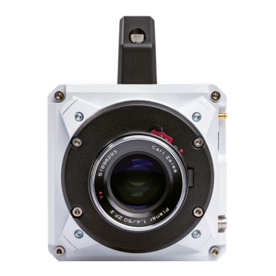
- Page 49 FRONT VIE W N G S Chapter 9: FAQs & Suppor t | 4 5...
- Page 50 LEF T / RIGHT Vision Research, Inc. | Phantom T-Series Camer a Manual...
-
Page 51: Faqs & Support
TOP / BOT TOM Chapter 9: FAQs & Suppor t | 47... -
Page 52: Connector Pin-Outs
Use these schematics to build custom cables at your own risk. Miswired cables can cause serious damage to the camera, which is not covered under warranty. Vision Research recommends only using cables supplied by Vision Research. PHANTOM T-SERIES BNC CONNECTORS NOMENCLATURE/FUNCTION Dedicated I/O - Trigger-In / active-low isolated input. - Page 53 All pin-out diagrams refer to the connector on the camera body. Part numbers indicated are for the cable’s connector. ETHERNET CONNECTOR (FEMALE) Cable 8-pin Fischer Part #SS 103 A058-130 WIRE NOMENCLATURE/FUNCTION Blue/White MDI2P Media Dependent 2 Positive Blue MDI2N Media Dependent 2 Negative Brown/White MDI3P Media Dependent 3Positive Brown...
- Page 54 RANGE DATA CONNECTOR (MALE) Cable 8-pin Fischer Part #S-103-Z-058-130 NOMENCLATURE/FUNCTION GND / Power Ground ROUT+ / Remote/Range Data Out (Positive), (RS-422); +5V maximum. 5Mbps; 60m max distance ROUT- / Remote/Range Data Out (Negative), (RS-422); +5V maximum. 5Mbps; 60m max distance RIN+ / Remote/Range Data In (Positive), (RS-422);...
- Page 55 These cameras can have a lot of memor y! How long does it take to save a shot? Phantom T-series cameras are available with 10Gb Ethernet and the unique Phantom CineMag interface for fast downloading. 10Gb Ethernet allows data transfer at up to 500 MB/second on optimized systems, which means all 144 GB of memory can be downloaded in approximately 4 minutes.
- Page 56 I see there are two power input por ts. How do these work? The Primary DC Input is where you plug the 160W A/C power supply provided with the camera. You can optionally connect a backup source of power, often a battery, to the secondary backup input.
- Page 57 Do T-Series cameras suppor t the use of Canon EOS lenses with software control for aper ture and focus? Yes, an optional Canon EOS lens mount is required, part #VRI-MNT-F4K-EOS. Vision Research can only guarantee compatibility with the lenses listed on the tested Canon lens compatibility list, which can be found in a FAQ on the phantomhighspeed.com website.
- Page 58 SUBMIT TING A SUPPORT TICKE T For technical product support, operation and application information or to request an RMA, please submit a ticket by filling out a form at www.phantomhighspeed-service. force.com or by emailing us at phantom-support@ametek.com. LIVE CUSTOMER AND TECHNICAL SUPPORT Serving the Americas: M-F 8:00 AM to 5:00 PM EST (GMT -4:00) T: +1.973.696.4500...
-
Page 59: Regulatory
REGULATORY CE - 2020 CE Emissions CE Compliant - EN 61326-1, Class A CE Immunity CE Compliant - EN 61326-1, Class A CFR 47, Part 15, Subpart B & ICES-003 Class A Safety IEC 60950-1 KC - 2020 Country of Origin: USA R-R-VRi-T1340: All models Phantom T1340 KC Emissions KC Compliant - KN32... - Page 60 WWW.PHANTOMHIGHSPEED.COM The contents of this manual are subject to change without notification. PN: ZDOC-64118-MA-0001 Rev 1 Last Updated: September 2020 100 Dey Road Wayne, NJ 07470 USA +1.973.696.4500...
Need help?
Do you have a question about the PHANTOM T-1340 and is the answer not in the manual?
Questions and answers