
Related Manuals for Ametek PHANTOM Micro C211


Summary of Contents for Ametek PHANTOM Micro C211
- Page 1 PHANTOM HIGH-SPEED CAMERA Miro C211 USER MANUAL When it’s too fast to see, and too important not to. ®...
- Page 2 The contents of this manual are subject to change without notification. PN: ZDOC-64078-MA-0004 Rev 1 Last Updated: December 2022 P H A N T O M H I G H S P E E Vision Research, Inc. | Miro C211 Camer a Manual...
-
Page 3: Table Of Contents
When it’s too fast to see, and too important not to. ® Miro C211 User Manual Introduction Connectors Quick Start Guide PCC Phantom Software Signals & Programmable I/O Support D . C O M... -
Page 4: Miro C211
Miro C211 Vision Research, Inc. | Miro C211 Camer a Manual... -
Page 5: Introduction
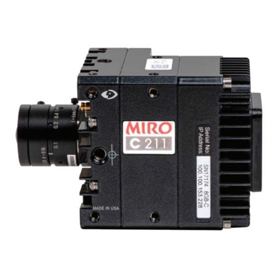
The Phantom Miro C211 is a member of the Miro C-Series family of small, flexible ® ® cameras designed for a large variety of applications and analyses. The C211 is designed for Ease-of-Use. It is small, sturdy, uses a variety of inexpensive C-mount lenses, and connects with standard Ethernet and BNC cables. - Page 6 CAMERA CONTROL Phantom cameras come with PCC software for Ethernet-based setup and control. IMAGE STORAGE The Miro C211 has either 8GB or 16GB of internal memory and a standard 240GB internal, non-removable CineFlash. The CineFlash allows users to quickly store a number of experiments or shots before downloading to a PC.
- Page 7 ADDITIONAL FEATURES Set new CSR default: Set a CSR in PCC with customer-selected settings. If settings are not changed, the camera may be powered off and on and the CSR will remain active. Cameras must be set in full resolution. Programmable I/O: Assign and define signal parameters for each programmable I/O port.
- Page 8 Miro C211 Rear View Vision Research, Inc. | Miro C211 Camer a Manual...
-
Page 9: Connectors
Mini XLR connector connects to +16-32VDC +16-32VDC Power Supply. Input: when a TTL pulse (rising / falling edge) is TRIGGER detected, camera triggers. BNC connector for HD video. RJ45 connector connects via Gb Ethernet to a control ETHERNET unit computer / laptop for camera control communication. Strobe (Default) AUX 1 Other signals available through Programmable I/O drop down list in PCC. -
Page 10: Quick Start Guide
Q U I C K S T A R T G U I D E Vision Research, Inc. | Miro C211 Camer a Manual... - Page 11 Phantom cameras are typically controlled with PCC software through a dedicated Ethernet network. PCC is compatible with the 64-bit version of Windows 10 operating systems. The latest version can be downloaded at: www.phantomhighspeed.com/PCC ASSIGNING A Gb CAMERA NETWORK Connecting the camera using Gb Ethernet simply requires the computer to detect the IP address range of Phantom cameras.
- Page 12 The NetConfig Utility will show all network interfaces currently installed in the PC. Identify the one that will be physically connected to the camera (this process can be done with or without a camera connected at the time). Click ‘Config Adapter’, which will then adjust the IP Address and Subnet to the first one available within the 100.100 network that all Phantom cameras are pre-configured to work with.
- Page 13 Cover the lens and click the ‘CSR‘ button to perform a Current Session Reference. A CSR is a black reference for that session. It is required before capturing the first cine and after changing any recording parameters. With color cameras, perform a White Balance by right-clicking an area of the image that is neutral gray or white, as long as it is not 100 percent saturated.
- Page 14 TRIGGER At the end of the action, click the ‘Trigger’ button at the bottom of the ‘Live’ panel or provide an external trigger signal (TTL pulse) via the Trigger connector. PLAYBACK AND EDIT CINE Click the ‘Play’ tab to Scrub through the timeline or use the ‘Video Control’ buttons to locate the first image to be saved.
- Page 15 The latest version of Phantom PCC software can be downloaded from the Vision Research website: www.phantomhighspeed.com/pcc This manual covers the most commonly used functions. See the ‘PCC Help’ file for details of other settings. PRE-INSTALLATION Phantom Camera Control (PCC) software operates with Microsoft Windows 10. The computer and cameras must be associated with the same sub-network to communicate with one another.
- Page 16 CONTROL TABS PCC provides three control tabs: ‘Live,’ ‘Play’ and‘Manager.’ When first started, the ‘Manager’ tab is selected. Connected cameras are selected for use and naming in this tab. It is also used to manage saved Cine files. All camera control and capture parameters (sample rate, exposure time, etc.) are performed in the ‘Live’...
- Page 17 units to set are EDR (Extreme Dynamic Range, not compatible on all models) and PTF (Post Trigger Frames) covered later in this section. SELECTING A CAMER A Select the camera(s) to be controlled listed in the ‘Manager’ tab, or select the camera(s) from the ‘Camera’...
- Page 18 IMAGE DISPL AY The ‘Zoom Actual Size’ toolbar button resizes the images being displayed in the ‘Preview/ Playback’ panel to their actual size. The ‘Zoom Fit’ toolbar button resizes the images to fit the panel. Images can also be zoomed to a specific magnification ratio by selecting a number from the pull-down list to the right of the ‘Zoom Fit’...
- Page 19 Backup & Restore: Allows for user and factory settings to be saved and recalled from the camera’s memory. Resolution: Sets the camera’s acquisition resolution. There are several options in the pull-down menu. Alternatively, type in a value and the closest valid resolution will be set. Sample Rate: Sets the acquisition frame rate in frames- per-second (fps).
- Page 20 ‘External Sync’ instructs the camera to use one of the following options: • Internal: Camera uses its internal crystal oscillator to drive the frame rate. • External: Camera uses externally supplied frame sync clock pulse to drive the frame rate. This can be used to synchronize two cameras together via F-Sync. •...
- Page 21 RE VIE WING A CINE Once the camera has completed recording a Cine in the camera’s RAM or Flash, it can be reviewed by selecting it from the ‘Cine’ pull-down selection list in the PCC ‘Play’ tab. A previously saved Cine stored on the computer’s hard drive can be opened using the ‘Open File’...
- Page 22 EDITING AND S AVING A CINE Using the following ‘Video Control’ buttons, locate the first image of the Cine to be saved and click the ‘Mark-In’ button. Locate the last image of the Cine to be saved and click the ‘Mark-Out’ button.
- Page 23 like’ formats (meaning the entire clip will be saved as a single file), while the formats below the line are image formats (meaning each frame of Cine will be saved as a sequence of images). To convert a Cine to a ‘movie-like’ format, select the desired format from the list, navigate to the destination folder, assign a file name to the clip and save.
- Page 24 P R O G R A M M A B L E I / O Vision Research, Inc. | Miro C211 Camer a Manual...
-
Page 25: Signals & Programmable I/O
INTRODUCTION TO SIGNALS Phantom cameras incorporate multiple hardware signals to interface to external devices. The Aux ports on Phantom C211 cameras are programmable. The Programmable I/O ports have a default setting which will be set after a factory reset or by using the ‘signal default’ function in PCC. - Page 26 signals, the signal characteristics can be modified to better interface with external devices. In most cases, the signal polarity, filter time, delay and pulse width and edge (rising versus falling) can be set. Setting these characteristics is referred to as ‘Pulse Processor Control.’...
- Page 27 SUMMARY OF PULSE PROCESSOR SETTINGS Invert: Inverts the signal at the output of the pulse processor. Falling: Selects ‘Falling Edge’ mode for the pulse processor. This mode is only relevant if the ‘Width’ is also specified. When the ‘Falling’ token is present together with ‘Width,’ the pulse processor will generate a negative pulse, triggered from the negative edge of the input signal.
- Page 28 Strobe: An isolated open collector output signal with 1k pull-up. When asserted (low) ‘Strobe’ indicates that the electronic shutter is open. Strobe is low for the duration of the exposure. F-Sync: The only signal can be set as an output or input. By default, it is output (sync- internal).
- Page 29 THE CORE SIGNALS Core signals are copies of externally generated signals, routed through the camera and output to assigned ports. Unless indicated otherwise, feedback is taken after any pulse processor for the input. Core signals can be pulse-processed before being output. Core Event: Feedback output from the ‘Event In’...
- Page 30 MIRO C211 TOP VIE W MIRO C211 BOT TOM VIE W M E C H A N I C A L D R A W I N Vision Research, Inc. | Miro C211 Camer a Manual...
- Page 31 MIRO C211 RIGHT / LEF T N G S Chapter 6: Suppor t | 27...
- Page 32 MIRO C211 FRONT / BACK REV. INITIA 10.0 29.5 39.5 29.0 79.0 10.0 16.0 40.0 29.5 32.0 59.0 Vision Research, Inc. | Miro C211 Camer a Manual 79.0...
- Page 33 MIRO C211 STATUS INDICATORS Miro C211 Rear View TRIGGER LED COLOR CAMERA STATE White Camera Booting Green Preview Mode Capture Mode Red Flashing Trigger mode, and saving images ETHERNET LED COLOR CAMERA STATE Green EtherLink Active Amber Ethernet Activity Chapter 6: Suppor t | 29...
- Page 34 Use these schematics to build custom cables at your own risk. Miswired cables can cause serious damage to the camera, which is not covered under warranty. Vision Research recommends only using cables supplied by Vision Research. These pin-out diagrams refer to the connector on the camera body. Part numbers indicated are for the cable’s connector.
- Page 35 BNC CONNECTORS Multiple signal ports NOMENCLATURE/FUNCTION Input: when a TTL pulse (rising / falling edge) is detected, Trigger camera triggers Output: for HD video • Default setting: Strobe Aux 1 • Other signals available through Programmable I/O drop down list in PCC. Refer to Section 5, Programmable I/O. •...
- Page 36 MIRO C FAQS Can I use any Ethernet cable with the Miro C211? Yes. We include an Ethernet cable and a BNC cable with the camera, just to get you started. But any Ethernet or BNC cable will work. Can I use my F-mount lens with the Miro C-Series cameras? Yes, with a converter.
- Page 37 If the camera doesn’t have a shutter, how can I per form a Current Session Reference? The Miro C’s do not have a shutter, but you can still perform a Current Session Reference (CSR). Just make sure you cover the lens before clicking the CSR button. What are the available signals for the C211? Trigger (dedicated BNC);...
- Page 38 without a sync source connected. In the PCC > Live > Advanced Settings menu, check the External Sync setting to ensure that ‘Internal’ is selected. Restoring the factor y defaults. If the camera is stuck in an unusual state it may be useful to restore the camera’s factory defaults.
- Page 39 MAINTENANCE Sensor Cleaning Technical Tips • Sensor cleaning should only be attempted by experienced imaging professionals. • Use a small, but powerful flashlight to look at the sensor and filter, it’s easier to spot the dust. • Sensor cleaning must be done in a clean and controlled environment. •...
-
Page 40: Support
SUBMIT TING A SUPPORT TICKE T For technical product support, operation and application information or to request an RMA, please submit a ticket by filling out a form at www.phantomhighspeed-service. force.com or by emailing us at phantom-support@ametek.com. LIVE CUSTOMER AND TECHNICAL SUPPORT Serving the Americas: M-F 8:00 AM to 5:00 PM EST (GMT -4:00) T: +1.973.696.4500... - Page 41 REGULATORY CE - 2019 CE Emissions CE Compliant - EN 61326-1, Class A CE Immunity CE Compliant - EN 61326-1, Class A CFR 47, Part 15, Subpart B & ICES-003 Class A Safety IEC 60950-1 KC - 2022 Country of Origin: USA R-R-VRi-MiroC211: All models Phantom C211 Series KC Emissions KC Compliant - KS C 9832...
- Page 42 WWW.PHANTOMHIGHSPEED.COM The contents of this manual are subject to change without notification. PN: ZDOC-64078-MA-0004 Rev 1 Last Updated: December 2022 100 Dey Road Wayne, NJ 07470 USA +1.973.696.4500...