
Subscribe to Our Youtube Channel
Related Manuals for Ametek PHANTOM T Series


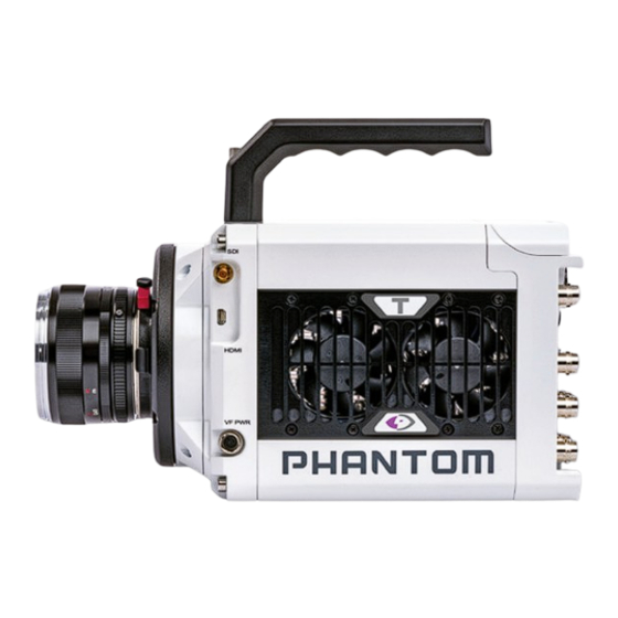
Summary of Contents for Ametek PHANTOM T Series
- Page 1 PHANTOM HIGH-SPEED CAMERA T-SERIES MANUAL When it’s too fast to see, and too important not to. ®...
-
Page 2: Table Of Contents
When it’s too fast to see, and too important not to. ® Phantom T-Series Manual Camera Overview 2 Connectors 3 Network Setup & Quick Start Guide 4 On-Camera Controls & On-Screen Display 5 Working with Phantom CineMag and CineStation 6 Phantom PCC Software: - Camera Operation - Playback and Downloading - File Conversion... - Page 3 INTRODUCTION Phantom T-Series high-speed cameras are available with either a one or four-megapixel resolution sensor, which both have their own unique characteristics and benefits. • The T1340 4Mpx camera was developed for applications where high resolution is beneficial including microscopy, tracking projectiles and objects far in the distance and for use with imaging techniques for flow visualization and Digital Image Correlation (DIC).
-
Page 4: Camera Overview
ADDITIONAL FEATURES that consists of large 27 micron pixels, rather than the T1340’s normal 13.5 micron pixels. This results in a frame rate boost at low resolutions. Both monochrome and Programmable I/O: Assign and define signal parameters for each Programmable I/O port. color cameras support the Binning function, note that the image output is always Available signals include Strobe, Ready, F-Sync, Pre-Trigger, Event, Memory Gate and monochrome with Binning enabled. -
Page 5: Connectors
BNC outputs 3G-SDI video 3 STROBE /P Programmable I/O, Port ID = P3. Default signal = Strobe 5 READY /P Programmable I/O, Port ID = P5. Default signal = Ready 2 TC IN Timecode-in fixed port for IRIG-B (Modulated/Unmodulated) 1 TRIGGER Trigger-in fixed port. - Page 6 Phantom cameras are typically controlled with PCC software through a dedicated Ethernet network. PCC is compatible with the 32- and 64-bit versions of Windows 10 operating systems. The latest version can be downloaded at: www.phantomhighspeed.com/PCC Gb & 10Gb ETHERNET Phantom T-Series cameras come with standard Gigabit (Gb) Ethernet and have the option to be configured with 10-Gigabit (10Gb) Ethernet as a secondary means of connection.
- Page 7 ASSIGNING A Gb CAMERA NETWORK WORKING WITH 10Gb ETHERNET Connecting the camera using Gb Ethernet simply requires the computer to detect the IP STEP 1: IDENTIF Y NE T WORK ADAPTER address range of Phantom cameras. Identify a 10GBase-T network card or adapter for the computer itself. For desktop (tower) PCC software includes a Network Configuration Utility which will launch automatically PCs, Vision Research specifically recommends Intel PCIE cards.
- Page 8 FINE-TUNE SETTINGS With the Network Setup complete, the following steps will guide you through a simple capture and save process. After CSR and White Balance are performed, adjust settings, aperture and/or lighting to get a good exposure. A CSR must be performed after any camera settings are adjusted. POWER ON CAMERA Connect the camera’s dedicated power supply to the Primary DC input, and move the ‘ARM’...
- Page 9 TRIGGER When camera is in capture mode (writing to internal RAM), button glows red. A single tap will trigger the camera. When a Cine is captured, the button glows green. When in video playback mode, tap the trigger button to exit the menu. When the menu is active, tap the trigger button to go live.
- Page 10 ON-SCREEN DISPLAY (OSD) OVERVIEW TIMECODE Indicates the IRIG timecode stamped to each frame. The On-Screen Display (OSD) provides valuable information about the camera’s current status over the video outputs along with the live or playback images. BUFFER BAR WITH TRIGGER POINT This ‘timeline’...
- Page 11 MENU OVERVIEW 1/6 CAMERA The On-Camera Control menu provides access to major camera settings for operation The CAMERA menu page includes controls for the fundamental settings. and playback. The menu is activated with a press of the menu knob and displayed as an SPEED overlay to the camera’s video outputs (SDI and HDMI) Sets the acquisition frame...
-
Page 12: Phantom Pcc Software
3/6 SETTINGS 2/6 IMAGE The SETTINGS page allows The IMAGE page allows for control for user setups to be saved of image processing and video and recalled. settings. These image settings are adjustments applied to Cine Raw 0 – 5 files as metadata. - Page 13 5/6 AUTO CAPTURE A CINE USING THE OCC The AUTO menu defines some of the Ensure camera is in ‘Capture’ mode, then Tap the ‘Trigger’ button to trigger the camera. camera’s automatic functions. With the Cine in RAM, tap the ‘Playback’ button. The video output will switch to playback view, where you must select the Cine for playback.
- Page 14 PHANTOM CINEMAG V INDICATORS On the back of the Phantom CineMag are a number of LED indicators that show the current Phantom CineMag status. MAG CAPACIT Y INDICATOR When a Phantom CineMag is empty, all lights will be illuminated. As material is recorded to the mag, the lights will turn off from left to right.
- Page 15 SAVING FROM A CINEMAG Erase progress is indicated on the video OSD and by a progress bar in the software. Once complete, all data on the CineMag will be erased and it will be ready for recording again Vision Research recommends to download footage from a CineMag in the Cine Raw immediately.
- Page 16 The latest version of Phantom PCC software can be downloaded from the Vision Research website: www.phantomhighspeed.com/pcc This manual covers the most commonly used functions. See the ‘PCC Help’ file for details of other settings. PHANTOM CAMERA CONTROL (PCC) APPLICATION OVERVIEW TOOLBAR The ‘Toolbar’...
- Page 17 SELECTING A CAMER A PHANTOM VIDEO PL AYER (PVP) APPLICATION OVERVIE W PVP can be launched directly from the Select the camera(s) to be controlled listed in the ‘Manager’ tab, or select the camera(s) desktop shortcut or by the ‘Video Out’ from the ‘Camera’...
- Page 18 IMAGE DISPL AY Backup & Restore: Allows for user and factory settings to be saved and recalled from the camera’s memory. The ‘Zoom Actual Size’ toolbar button resizes the images being displayed in the ‘Preview/ Resolution: Sets the camera’s acquisition resolution. There Playback’...
- Page 19 For direct recording to a CineMag, set ‘R/S’ (Run/Stop) mode by selecting ‘External Sync’ instructs the camera to use one of the following options: the ‘Direct Recording to CineMag’ box in the ‘Flash Memory’ section. Start • Internal: Camera uses its internal crystal oscillator to drive the frame rate. recording by clicking the red ‘Record’...
- Page 20 EDITING AND S AVING A CINE like’ formats (meaning the entire clip will be saved as a single file), while the formats below the line are image formats Using the following ‘Video Control’ buttons, locate the first image of the Cine to be saved (meaning each frame of Cine will be saved as a sequence of and click the ‘Mark-In’...
-
Page 21: Signals And Programmable I/O
T-SERIES SIGNAL ASSIGNMENTS Port 1 Trigger (fixed) Port 2 Timecode-in (fixed) Port 3 (P3) Prog I/O-Default Strobe Port 4 (P4) Prog I/O-Default F-Sync Port 5 (P5) Prog I/O-Default Ready INTRODUCTION TO SIGNALS Phantom cameras incorporate multiple hardware signals to interface to external devices. These are used to drive the camera’s frame rate, shutter and trigger, to output to other devices, to monitor with an oscilloscope, and to import test sensor data using a Data Acquisition (DAQ) unit. - Page 22 PCC INTERFACE SUMMARY OF PULSE PROCESSOR SETTINGS The ‘Camera Signals’ menu, located in the Invert: Inverts the signal at the output of the pulse processor. ‘Live’ tab, provides access to and control over Falling: Selects ‘Falling Edge’ mode for the pulse processor. This mode is only relevant if the these Programmable I/O signals.
-
Page 23: Accessories
hundred ns depending on camera model) negative pulse with the falling edge is used as timing reference. Input signal is active on falling edge. (Default state is high.) TC-Out: A positive polarity time code signal. Normally an unmodulated (dc-shifted) IRIG-B (at RS-232 levels) which follows the internal time base of the camera. It is recommended not to process the ‘TC-Out,’... - Page 24 C- MOUNT AND M42 MOUNT SIDE MOUNTING BRACKET A threaded C-mount or ‘Universal’ M42 lens When the sensor resolution is windowed vertically, the frame mount may be required for specialized optics, rates are increased more than they would be when windowed such as microscopes for scientific imaging or horizontally.
- Page 25 RE AR VIE W FRONT VIE W M E C H A N I C A L D R A W I N G S Vision Research, Inc. | Phantom T-Series Camer a Manual Chapter 9: FAQs & Suppor t | 4 5...
- Page 26 TOP / BOT TOM LEF T / RIGHT Vision Research, Inc. | Phantom T-Series Camer a Manual Chapter 9: FAQs & Suppor t | 47...
- Page 27 Use these schematics to build custom cables at your own risk. Miswired cables All pin-out diagrams refer to the connector on the camera body. can cause serious damage to the camera, which is not covered under warranty. Part numbers indicated are for the cable’s connector. Vision Research recommends only using cables supplied by Vision Research.
- Page 28 RANGE DATA CONNECTOR (MALE) These cameras can have a lot of memor y! How long does it take to save a shot? Cable 8-pin Fischer Part #S-103-Z-058-130 Phantom T-series cameras are available with 10Gb Ethernet and the unique Phantom NOMENCLATURE/FUNCTION CineMag interface for fast downloading.
- Page 29 I see there are two power input por ts. How do these work? Do T-Series cameras suppor t the use of Canon EOS lenses with software control for aper ture and focus? The Primary DC Input is where you plug the power supply provided with the camera. You can optionally connect a backup source of power, often a battery, to the secondary backup Yes, an optional Canon EOS lens mount is required, part #VRI-MNT-TSERIES-EOS.
- Page 30 For technical product support, operation and application information or to request an CFR 47, Part 15, Subpart B & ICES-003 Class A RMA, please submit a ticket by filling out a form at www.phantomhighspeed-service. force.com or by emailing us at phantom-support@ametek.com. Safety IEC 60950-1...
-
Page 31: Pn: Zdoc-64118-Ma-0001 Rev 2
WWW.PHANTOMHIGHSPEED.COM The contents of this manual are subject to change without notification. PN: ZDOC-64118-MA-0001 Rev 2 Last Updated: September 2021 100 Dey Road Wayne, NJ 07470 USA +1.973.696.4500...
Need help?
Do you have a question about the PHANTOM T Series and is the answer not in the manual?
Questions and answers