Table of Contents
Advertisement
Quick Links
MP42E
M-126 Precision Microtranslation Stage
User Manual
Version: 3.0.0
PI miCos GmbH, Freiburger Strasse 30, 79427 Eschbach, Germany
Phone +49 7634 5057-0, Fax +49 7634 5057-99, Email info@pimicos.com, www.pi.ws
Date: 20.01.2021
This document describes the following precision
micropositioning stages:
M-126.CG1, M-126.DG1:
With DC gear motor, rotary encoder
M-126.PD1, M-126.PD2:
With ActiveDrive DC motor, rotary encoder
M-126.2S1:
With 2-phase stepper motor
M-126.M0
For manual operation
Advertisement
Table of Contents

Related Manuals for PI M-126


Summary of Contents for PI M-126
- Page 1 M-126.PD1, M-126.PD2: With ActiveDrive DC motor, rotary encoder M-126.2S1: With 2-phase stepper motor M-126.M0 For manual operation PI miCos GmbH, Freiburger Strasse 30, 79427 Eschbach, Germany Phone +49 7634 5057-0, Fax +49 7634 5057-99, Email info@pimicos.com, www.pi.ws...
- Page 2 BiSS is a registered trademark of iC-Haus GmbH. © 2020 Physik Instrumente (PI) GmbH & Co. KG, Karlsruhe, Germany. The text, photographs, and drawings in this manual are protected by copyright. With regard thereto, Physik Instrumente (PI) GmbH & Co. KG retains all the rights.
-
Page 3: Table Of Contents
Mounting the M-126 onto a Surface ................ 19 Fixing the Load to the M-126 ................... 20 Connecting the M-126 to the Controller ..............21 Connecting the Power Supply to the M-126 ............22 Startup General Notes on Startup ..................23... - Page 4 Starting and Operating the M-126 ................23 Maintenance General Notes on Maintenance ................27 Doing a Maintenance Run ..................27 Cleaning the M-126 ....................28 Troubleshooting Possible Causes and Correction ................29 Customer Service Technical Data 10.1 Specifications ......................33 10.1.1 Data Table ....................
-
Page 5: About This Document
About this Document Objective and Target Audience of this User Manual This manual contains information on using the M-126 as intended. It assumes that the reader has a fundamental understanding of basic servo systems as well as motion control concepts and applicable safety procedures. -
Page 6: Definition Of Terms
Figures For better understandability, the colors, proportions, and degree of detail in illustrations can deviate from the actual circumstances. Photographic illustrations may also differ and must not be seen as guaranteed properties. Version: 3.0.0 MP42E M-126 Precision Microtranslation Stage... -
Page 7: Other Applicable Documents
1 About this Document Other Applicable Documents The devices and software tools from PI mentioned in this documentation are described in separate manuals. Product Document Positioners with Electric Motors MP119EK Short Instructions C-863.12 Mercury Controller MS251 User Manual C-884.xDC DC Motor Controller MS243 User Manual C-663.12 Mercury Step Stepper Motor Controller... -
Page 9: Safety
Safety Intended Use The M-126 is a laboratory device as defined by DIN EN 61010. It is intended for indoor use and use in an environment that is free of dirt, oil and lubricants. In accordance with its design, the M-126 is intended for single-axis positioning, adjusting and shifting of loads at different velocities. - Page 10 Do the work only if the user manual is complete. Missing information due to an incomplete user manual can result in minor injury and damage to equipment. Install and operate the M-126 only after you have read and understood this user manual.
-
Page 11: Product Description
24 V power adapter M-126.2S1 Microtranslation stage, 25 mm travel range, 2-phase stepper motor M-126.M0 Microtranslation stage, 25 mm travel range, manual For further technical data, see the specifications (p. 33). M-126 Precision Microtranslation Stage MP42E Version: 3.0.0... -
Page 12: Product View
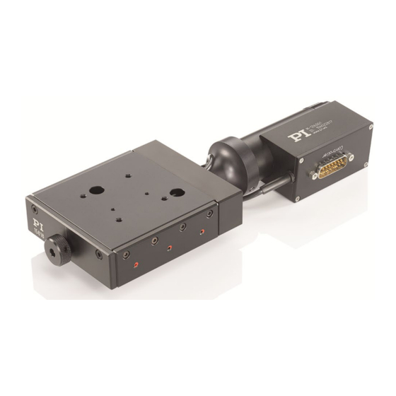
3 Product Description Product View Figure 1: Elements of the M-126 with electric drive, example: M-126.DG1 1. Base body with platform 2. Motor 3. Connectors (controller, for M-126.PDx additionally: supply voltage) 4. Rotary knob of the drive screw for moving the platform by hand Version: 3.0.0... -
Page 13: Direction Of Motion
3 Product Description Direction of Motion Figure 2: Direction of motion of the M-126 Arrow direction: Direction of motion on positive (+) and negative (-) command M-126 Precision Microtranslation Stage MP42E Version: 3.0.0... -
Page 14: Product Labeling
3 Product Description Product Labeling Figure 3: Position of the product labeling 1. Manufacturer's logo 2. Product name, serial number, Manufacturer's address (website) 3. Connection label Version: 3.0.0 MP42E M-126 Precision Microtranslation Stage... -
Page 15: Scope Of Delivery
4 socket head screws, M4×20 ISO 4762 Hex key, AF 3 Accessories The following articles are not in the scope of delivery of the M-126 and must be ordered separately, if required. Order number Description M-126.80 Adapter plate for mounting M-126 stages onto honeycomb platforms (metric and inches) M-125.90... -
Page 16: Suitable Controllers
3 Product Description Suitable Controllers The version of the M-126 with electric drive must be connected to a suitable controller. The following controllers from PI are suitable for operating the M-126: Models Controller M-126.XG1, M-126.PDx C-863, C-884 M-126.2S1 C-663 The required PC software is included in the scope of delivery of the controllers from PI. -
Page 17: Integrated Pwm Amplifier
3.8.4 Integrated PWM Amplifier The M-126.PDx models are equipped with a PWM amplifier ("ActiveDrive concept"). The PWM amplifier only receives the PWM control signals from the controller, whereas the supply voltage is provided via an external power adapter. The ActiveDrive concept allows high motor power and dynamics at low power loss. -
Page 19: Unpacking
4 Unpacking Unpacking 1. Unpack the M-126 with care. 2. Compare the contents with the scope of delivery according to the contract and the delivery note. 3. Inspect the contents for signs of damage. If any parts are damaged or missing, contact our customer service department (p. -
Page 21: Installation
Unintentional changes in the position of the platform can damage the drive, the load or the surroundings. If the M-126 is mounted vertically, make sure that the installed load is lower than the holding force of the drive. -
Page 22: Turning The Connectors Of The M-126
The base body (with platform) and motor (with connectors) move together when the M-126 is operating. Make sure that the M-126 has enough room to move and the connecting cables are long enough. If necessary, turn the connectors of the M-126 to a position suitable for your application. -
Page 23: Mounting The M-126 Onto A Surface
There is a mounting plate with two threaded holes (mounting holes) on the bottom of the M- 126. The M-126 is mounted on and underlying surface via this plate. Mounting is from above. Access to the mounting holes is via two through-holes in the M-126's platform. -
Page 24: Fixing The Load To The M-126
Moving the platform with the help of the drive screw's rotary knob − 2. Align the M-126 on the underlying surface so that the mounting holes in the M-126 and underlying surface are in line. 3. Tighten the screws in the mounting holes from above completely. -
Page 25: Connecting The M-126 To The Controller
5 Installation You have prepared the load so that it can be fixed to the mounting holes in the M-126's platform: The gap between the center of gravity of the load and the center of the platform is −... -
Page 26: Connecting The Power Supply To The M-126
5 Installation Connecting the Power Supply to the M-126 Connecting a power adapter is only necessary for the M-126.PDx models. Requirements The power cord is not connected to the power socket. Tools and accessories Supplied components: 24 V wide-range-input power supply −... -
Page 27: Startup
Do not place any objects in areas where they can be caught by moving parts. Before connecting the M-126, check whether a macro is defined as the startup macro in the controller and cancel the selection of the startup macro if necessary. - Page 28 1. M-126.PDx models only: Connect the power adapter's cord to the power socket. 2. Start the controller (refer to the user manual for the controller). Configure the controller during startup using the PC software for the M-126 used (see the user manual for the controller, and the PC software): −...
- Page 29 Negative limit switch position on the connector side, reference edge in the middle of the travel range, positive limit switch position opposite the negative limit switch Operating parameters for the M-126 with ActiveDrive DC motor Positioner M-126.PD1 / M-126.PD2 Unit...
- Page 30 Negative limit switch position on the connector side, reference edge in the middle of the travel range, positive limit switch position opposite the negative limit switch Operating parameters for the M-126 with 2-phase stepper motor Positioner M-126.2S1 Unit Drive screw pitch Motor M-126.2S1...
-
Page 31: Maintenance
If you move the M-126 continuously over a short travel range (<20 % of the entire travel range) in industrial operation, do a run across the entire travel range every 15 operating hours or at least after 30 days. -
Page 32: Cleaning The M-126
Cleaning the M-126 Requirements You have disconnected the M-126 from the controller. Cleaning the positioner When necessary, clean the surface of the M-126 with a cloth dampened lightly with a mild cleanser or disinfectant. Version: 3.0.0 MP42E M-126 Precision Microtranslation Stage... -
Page 33: Troubleshooting
Troubleshooting Possible Causes and Correction Problem Possible causes Solution Reduced positioning When the M-126 is mounted Do not exceed the maximum permissible accuracy vertically: Load exceeds the loads according to the specifications (p. holding force of the drive 33). - Page 34 Software for the affected axis. Refer to the user manual for the controller for details. Platform has triggered the If you use a controller from PI: limit switch. 1. Switch the servo mode on in the PC software for the affected axis again.
-
Page 35: Customer Service
9 Customer Service Customer Service For inquiries and orders, contact your PI sales engineer or send us an email (mailto:service@pi.de). If you have any questions concerning your system, provide the following information: − Product and serial numbers of all products in the system Firmware version of the controller (if applicable) −... -
Page 37: Technical Data
10 Technical Data Technical Data 10.1 Specifications 10.1.1 Data Table M-126.CG1 M-126.DG1 M-126.PD1 M-126.PD2 M-126.2S1 M-126.M0 Unit Active axes Motion and M-126.CG1 M-126.DG1 M-126.PD1 M-126.PD2 M-126.2S1 M-126.M0 Unit positioning Travel range Integrated sensor Rotary Rotary Rotary Rotary – – encoder... - Page 38 10 Technical Data Mechanical M-126.CG1 M-126.DG1 M-126.PD1 M-126.PD2 M-126.2S1 M-126.M0 Unit properties Gear ratio 16807:243 2401:81 – – – – Motor resolution – – – – – Full steps/r Max. load capacity 200 Max. push/pull 40 / 40 50 / 50...
-
Page 39: Maximum Ratings
M-126.2S1 24 V 0 Hz 10 W 10.1.3 Ambient Conditions and Classifications Pay attention to the following ambient conditions and classifications for the M-126: Area of application For indoor use only Maximum altitude 2000 m Relative humidity Max. 80 % for temperatures up to 31 °C Linearly decreasing to 50 % at 40 °C... -
Page 40: Limit Switch Specifications
Direction sensing by means of different signal levels on the left- and right-hand side of the reference switch: The signal level changes from 0 to +5 V when the reference switch is passed. Version: 3.0.0 MP42E M-126 Precision Microtranslation Stage... -
Page 41: Dimensions
10 Technical Data 10.2 Dimensions 10.2.1 M-126 All dimensions in mm. Note that a comma is used in the drawings instead of a decimal point. M-126.CG1 M-126 Precision Microtranslation Stage MP42E Version: 3.0.0... - Page 42 10 Technical Data M-126.DG1 Version: 3.0.0 MP42E M-126 Precision Microtranslation Stage...
- Page 43 10 Technical Data M-126.PDx M-126 Precision Microtranslation Stage MP42E Version: 3.0.0...
- Page 44 10 Technical Data M-126.2S1 Version: 3.0.0 MP42E M-126 Precision Microtranslation Stage...
- Page 45 10 Technical Data M-126.M0 M-126 Precision Microtranslation Stage MP42E Version: 3.0.0...
-
Page 46: Optional Accessories
10 Technical Data 10.2.2 Optional Accessories All dimensions in mm. Note that a comma is used in the drawings instead of a decimal point. M-126.80 adapter plate Version: 3.0.0 MP42E M-126 Precision Microtranslation Stage... - Page 47 10 Technical Data M-125.90 adapter bracket M-126 Precision Microtranslation Stage MP42E Version: 3.0.0...
-
Page 48: Pin Assignment
10 Technical Data 10.3 Pin Assignment 10.3.1 D-sub 15 (m) Controller Connection Figure 5: Sub-D 15 (m) controller connection, front view Models with DC gear motor: M-126.XG1 Signal Direction Not connected Motor (-) Input Motor (+) Input Ground Not connected... - Page 49 10 Technical Data Models with ActiveDrive DC motor: M-126.PDx Signal Direction Not connected Not connected Not connected Ground MAGN (PWM Magnitude) Input SIGN (PWM Sign), TTL Input + 5 V Input Negative limit switch, active high, TTL Output Positive limit switch, active high, TTL...
-
Page 50: Mini Xlr3 (M) Power Supply Connection
Negative limit switch, active low, TTL Output 10.3.2 Mini XLR3 (m) Power Supply Connection M-126.PDx models only Figure 6: Mini XLR 3 (m) power supply connection, front view Signal Direction 24 V DC supply voltage Input Not connected Version: 3.0.0 MP42E M-126 Precision Microtranslation Stage... -
Page 51: Old Equipment Disposal
Dispose of your old equipment according to international, national, and local rules and regulations. In order to fulfil its responsibility as the product manufacturer, Physik Instrumente (PI) GmbH & Co. KG undertakes environmentally correct disposal of all old PI equipment made available on the market after 13 August 2005 without charge. - Page 53 12 EU Declaration of Conformity EU Declaration of Conformity For the M-126, an EU Declaration of Conformity has been issued in accordance with the following European directives: EMC Directive RoHS Directive The applied standards certifying the conformity are listed below.
Need help?
Do you have a question about the M-126 and is the answer not in the manual?
Questions and answers