Table of Contents
Advertisement
Quick Links
MS235E
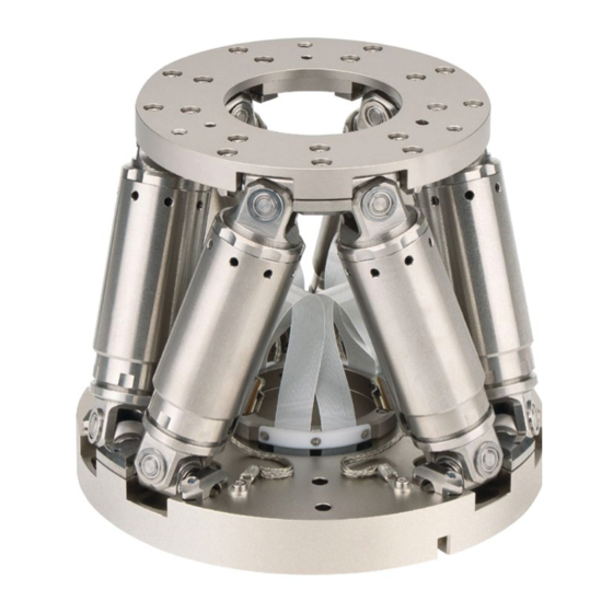
H-811 Hexapod Microrobot
User Manual
Version: 2.4.0
Physik Instrumente (PI) GmbH & Co. KG, Auf der Roemerstrasse 1, 76228 Karlsruhe, Germany
Phone +49 721 4846-0, Fax +49 721 4846-1019, Email info@pi.ws, www.pi.ws
Date: 24.08.2021
This document describes the following products:
H-811.I2
Miniature hexapod microrobot, brushless DC
motor, 5 kg load capacity, 10 mm/s max.
velocity, 0.5 m cable length. Connecting cables
are not in the scope of delivery and must be
ordered separately.
H-811.I2V
Miniature hexapod microrobot, brushless DC
motor, vacuum compatible to 10
load capacity, 10 mm/s velocity, cable set 2 m
vacuum side, feedthroughs. Air side connecting
cables are not included in the scope of delivery
and must be ordered separately.
H-811.F2
Miniature hexapod microrobot for optical
alignment, removable magnetic plate,
brushless DC motor, 5 kg load capacity, 10
mm/s max. velocity, 0.5 m cable length.
Connecting cables are not in the scope of
delivery and must be ordered separately.
H-811.S2
Miniature hexapod microrobot for high
dynamics applications, direct drive, 10 mm/s
maximum velocity, 1.5 kg load, 0.5 m cable
length. Connecting cables are not included in
the scope of delivery and must be ordered
separately.
hPa, 5 kg
-6
Advertisement
Table of Contents

Related Manuals for PI MS235E


Summary of Contents for PI MS235E
- Page 1 Connecting cables are not included in the scope of delivery and must be ordered separately. Physik Instrumente (PI) GmbH & Co. KG, Auf der Roemerstrasse 1, 76228 Karlsruhe, Germany Phone +49 721 4846-0, Fax +49 721 4846-1019, Email info@pi.ws, www.pi.ws...
- Page 2 BiSS is a registered trademark of iC-Haus GmbH. © 2021 Physik Instrumente (PI) GmbH & Co. KG, Karlsruhe, Germany. The text, photographs, and drawings in this manual are protected by copyright. With regard thereto, Physik Instrumente (PI) GmbH & Co. KG retains all the rights.
-
Page 3: Table Of Contents
Contents About this Document Objective and Target Audience of this User Manual..........1 Symbols and Typographic Conventions..............1 Figures ........................2 Other Applicable Documents ..................2 Downloading Manuals ....................3 Safety Intended Use ......................5 General Safety Instructions ..................5 Organizational Measures .................... - Page 4 Startup General Notes on Startup ..................37 Starting Up the Hexapod System ................38 Optional: Operating the Hexapod with a Separate 12 V Power Adapter ....39 Maintenance Performing a Maintenance Run ................43 Packing the Hexapod for Transport ................43 Cleaning the Hexapod ....................
-
Page 5: About This Document
Dangerous situation Failure to comply could lead to minor injury. Precautionary measures for avoiding the risk. NOTICE Dangerous situation Failure to comply could cause damage to equipment. Precautionary measures for avoiding the risk. H-811 Hexapod Microrobot MS235E Version: 2.4.0... -
Page 6: Figures
For better understandability, the colors, proportions, and degree of detail in illustrations can deviate from the actual circumstances. Photographic illustrations may also differ and must not be seen as guaranteed properties. Other Applicable Documents The devices and software tools from PI mentioned in this documentation are described in separate manuals. Device/program Document Document content C-887.5xx controller... -
Page 7: Downloading Manuals
If a manual is missing or problems occur with downloading: Contact our customer service department (p. 55). Downloading Manuals 1. Open the website www.pi.ws. 2. Search the website for the product number (e.g., P-882) or the product family (e.g., PICMA® bender). -
Page 9: Safety
The hexapod can only be used as intended in conjunction with a suitable controller available from PI (p. 8), which coordinates all motion of the hexapod. General Safety Instructions The H-811 is built according to state-of-the-art technology and recognized safety standards. -
Page 10: Measures For Handling Vacuum-Compatible Products
When handling the vacuum version of the hexapod, attention must be paid to appropriate cleanliness. At PI, all parts are cleaned before assembly. During assembly and measurement, powder-free gloves are worn. Afterwards, the hexapod is cleaned once again by wiping and shrink-wrapped twice in vacuum-compatible film. -
Page 11: Product Description
No accumulation of errors of individual axes No friction and torques from moving cables The hexapod is controlled with a controller that can be ordered separately from PI (p. 8). The position commands to the controller are entered as Cartesian coordinates. Model Overview Model... -
Page 12: Suitable Controllers
EtherCAT interface, motion stop C-887.533 6-axis controller for hexapods, TCP/IP, RS-232, benchtop device, incl. control of two additional axes, EtherCAT interface, motion stop, analog inputs To order, contact our customer service department (p. 55). Version: 2.4.0 MS235E H-811 Hexapod Microrobot... -
Page 13: Product View
H-811.I2, F2, .S2: Cables with a length of 0.5 m are installed permanently. H-811.I2V: Cables with a length of 2 m are installed permanently. Note that the cables required for connecting the H-811 to the electronics must be ordered separately. H-811 Hexapod Microrobot MS235E Version: 2.4.0... - Page 14 Accessories for connecting to the grounding system: 1 flat-head screw with cross recess, M4x8 ISO 7045 2 flat washers, form A-4.3 DIN 7090 2 lock washers, Schnorr Ø 4 mm N0110 Version: 2.4.0 MS235E H-811 Hexapod Microrobot...
- Page 15 Power supply cable for hexapods, drag-chain compatible, M12 m/f straight, 10 m C-815.82P20E Power supply cable for hexapods, drag-chain compatible, M12 m/f straight, 20 m To order, contact our customer service department (p. 55). H-811 Hexapod Microrobot MS235E Version: 2.4.0...
-
Page 16: Accessories
Available for hexapod mechanics H-811.F2 and H-811.I2 in combination with a C-887 hexapod controller that features a high-resolution analog input. Installation is done by a PI service engineer in a remote session. Contact will be established by PI after purchase. -
Page 17: Control
3.7.3 Control Der hexapod is intended for operation with a suitable controller from PI (p. 8). The controller makes it possible to command motion of individual axes, combinations of axes or all six axes at the same time in a single motion command. - Page 18 Translation Translations are described in the spatially-fixed coordinate system. The translational axes X, Y, and Z meet at the origin of the coordinate system (0,0,0). For further information, see the glossary (p. 89). Version: 2.4.0 MS235E H-811 Hexapod Microrobot...
- Page 19 Center of rotation in the top left corner of the platform 1. The U axis is commanded to move to position 10. The rotation around the U axis tilts the rotational axes V and W. H-811 Hexapod Microrobot MS235E Version: 2.4.0...
- Page 20 1. The V axis is commanded to move to position –10. The rotation takes place around rotational axis V, which was tilted during the previous rotation. The rotation around the V axis tilts the rotational axes U and W. Version: 2.4.0 MS235E H-811 Hexapod Microrobot...
- Page 21 The rotation takes place around the rotational axis W, which was tilted during the previous rotations. The W axis is always vertical to the platform level. The rotation around the W axis tilts the rotational axes U and V. H-811 Hexapod Microrobot MS235E Version: 2.4.0...
-
Page 22: Id Chip
(e.g., geometry data and control parameters). The configuration data for customized hexapods is only stored on the controller if the hexapod and controller are delivered together, or if PI was correspondingly informed before delivery of the controller. -
Page 23: Unpacking
When handling the vacuum version of the hexapod, attention must be paid to appropriate cleanliness. At PI, all parts are cleaned before assembly. Powder-free gloves are worn during assembly and measuring. In addition, the hexapod is wipe cleaned afterwards and then shrink- wrapped twice in vacuum-compatible film. - Page 24 4. Take the foam insert together with the hexapod out of the inner box carefully. 5. Tip the foam insert with the hexapod 90° onto its longitudinal side and put it onto an underlying surface. 6. Remove the clamp from the underneath of the foam insert. Version: 2.4.0 MS235E H-811 Hexapod Microrobot...
- Page 25 10. Compare the contents with the items listed in the contract and the packing list. If any of the parts are wrong or are missing, contact PI immediately. 11. Inspect the hexapod for signs of damage. If there is any sign of damage, contact PI immediately.
-
Page 27: Installation
Make sure that no collisions between the hexapod, the load to be moved, and the surroundings are possible in the workspace of the hexapod. H-811 Hexapod Microrobot MS235E Version: 2.4.0... -
Page 28: Determining The Permissible Load And Workspace
PIVeriMove, see the C887T0002 technical note (in the scope of delivery of the software). Determining the Permissible Load and Workspace Tools and Accessories PC with Windows operating system with the PI Hexapod Simulation Tool installed. For further information, see the A000T0068 technical note. -
Page 29: Grounding The Hexapod
Use one of the mounting holes in the motion platform (p. 72) for connection. If the motion platform and the load are connected conductively to each other, − connect the load to the grounding system. H-811 Hexapod Microrobot MS235E Version: 2.4.0... -
Page 30: Fixing The Data Transmission Cable With The Connector Holder
Figure 6: Mount the connector holder onto underlying surface Requirement You have read and understood the general notes on installation (p. 23). Tools and accessories Connector holder supplied including mounting kit: − Two M6x30 screws − Hex key 5.0 Version: 2.4.0 MS235E H-811 Hexapod Microrobot... -
Page 31: Mounting The Hexapod On A Surface
Mount the hexapod onto a flat surface. The recommended flatness of the surface is 20 µm. Requirements You have read and understood the general notes on installation (p. 23). Tools and accessories Hex key 3.0 and six of the supplied M4x25 screws (p. 9) H-811 Hexapod Microrobot MS235E Version: 2.4.0... -
Page 32: Fixing The Load To The Hexapod
Avoid high forces and torques on the motion platform during installation. Make sure that no collisions between the hexapod, the load to be moved, and the surroundings are possible in the workspace of the hexapod. Version: 2.4.0 MS235E H-811 Hexapod Microrobot... - Page 33 Three guides on the top of the motion platform Three balls on the bottom of the mounting plate Additional mounting plates are available as optional accessories (p. 12). Therefore, it is possible to replace the load to be aligned quickly. H-811 Hexapod Microrobot MS235E Version: 2.4.0...
- Page 34 Ø 3 mm F7, not in the scope of delivery H-811.F2 model only: If want to fix several loads to be aligned in quick succession: One additional mounting plate each per assembly, available as optional accessory (p. 12). Version: 2.4.0 MS235E H-811 Hexapod Microrobot...
-
Page 35: Connecting The Hexapod To The Controller
Connecting cables are not included in the scope of delivery and must be ordered separately (p. Vacuum feedthroughs are also included in the scope of delivery of a vacuum-compatible hexapod (p. 9). H-811 Hexapod Microrobot MS235E Version: 2.4.0... - Page 36 The data transmission cable and power supply cable are available separately (p. 9) If you want to operate a vacuum-compatible hexapod in a vacuum chamber: Suitable tools for installing the vacuum feedthrough Version: 2.4.0 MS235E H-811 Hexapod Microrobot...
- Page 37 5 Installation If necessary: Installing vacuum feedthroughs Figure 8: Vacuum feedthrough for data transmission (4668), dimensions in mm 4 holes, Ø6 x 45° for M3 countersunk screw H-811 Hexapod Microrobot MS235E Version: 2.4.0...
- Page 38 Pay attention to the assignment specified on the labeling of the sockets, plug − connectors, and cables. − Pay attention to the mechanical coding of connectors and sockets. − Do not use force. Use the integrated screws to secure the connections against accidental − disconnection. Version: 2.4.0 MS235E H-811 Hexapod Microrobot...
- Page 39 Cables with a length of 0.5 m are installed permanently. Power adapter, from the scope of delivery of the controller, 24 V DC output Data transmission cable* Power supply cable* * Must be ordered separately. H-811 Hexapod Microrobot MS235E Version: 2.4.0...
- Page 40 Data transmission cable, 3 m* Power supply cable, 3 m* Vacuum feedthrough for data transmission** Vacuum feedthrough for power supply** * Must be ordered separately. ** From the scope of delivery of the hexapod (p. 9). Version: 2.4.0 MS235E H-811 Hexapod Microrobot...
-
Page 41: Startup
Once you have established communication via TCP/IP or RS-232, send the CST? command. The response shows the hexapod, to which the controller is adapted. Only operate the hexapod with a controller whose configuration data is adapted to the hexapod. H-811 Hexapod Microrobot MS235E Version: 2.4.0... -
Page 42: Starting Up The Hexapod System
"Installation" (p. 23). You have read and understood the user manual of the controller. Version: 2.4.0 MS235E H-811 Hexapod Microrobot... -
Page 43: Optional: Operating The Hexapod With A Separate 12 V Power Adapter
C-501.12060M12 12 V wide input range power supply (60 W / 5 A), included with the H- 811.12PS option, which is available as optional accessory (p. 12). PC where PITerminal is installed (see user manual for the controller) H-811 Hexapod Microrobot MS235E Version: 2.4.0... - Page 44 12 V power adapter. See figure for an example. 3. Plug the power cord of the 12 V power adapter into the power socket. 4. Start and operate the controller (see user manual for the controller). Version: 2.4.0 MS235E H-811 Hexapod Microrobot...
- Page 45 8. If there is an M12 screw plug, remove it from the controller's 24 V output (24 V Out 7 9. Connect the hexapod to the 24 V output of the controller. For further information, see "Connecting the Hexapod to the Controller" (p. 31). H-811 Hexapod Microrobot MS235E Version: 2.4.0...
-
Page 47: Maintenance
Packing the Hexapod for Transport NOTICE Impermissible mechanical load! Impermissible mechanical load can damage the hexapod. Only ship the hexapod in the original packaging. Only hold the hexapod by the base plate. H-811 Hexapod Microrobot MS235E Version: 2.4.0... - Page 48 (p. 26)). e) Remove the hexapod from the underlying surface. 3. Pack each connector of the hexapod separately in electrostatic dissipative film. 4. Pack the hexapod in electrostatic dissipative film to protect against dirt. Version: 2.4.0 MS235E H-811 Hexapod Microrobot...
- Page 49 5. Grip the base plate of the hexapod and lay it sideways into one half of the foam insert. Make sure that the hexapod is correctly aligned to the recesses in the insert. 6. Align the second half of the foam insert and put it onto the hexapod. H-811 Hexapod Microrobot MS235E Version: 2.4.0...
- Page 50 Align the foam insert so that the clamp and therefore the hexapod's base plate are pointing downwards . b) Lay the cables onto the top of the foam insert. Avoid bending the cables. Version: 2.4.0 MS235E H-811 Hexapod Microrobot...
- Page 51 Lower the foam insert with the hexapod into the inner box carefully. 10. Close the inner box. 11. Put four cushioned corners onto the inner box. 12. Close the outer box. 13. Secure the box on the pallet. H-811 Hexapod Microrobot MS235E Version: 2.4.0...
-
Page 52: Cleaning The Hexapod
If necessary, clean the surfaces of the hexapod with a cloth that is dampened with a mild cleanser or disinfectant. Only when the hexapod is used in vacuum: Touch the hexapod only with powder-free gloves. If necessary, wipe the hexapod clean. Version: 2.4.0 MS235E H-811 Hexapod Microrobot... -
Page 53: Troubleshooting
Carry out a tuning of the Unsuitable control is bad. parameters. parameters for the application Contact our customer service department (p. 55). The system behavior has changed due to an increasing ease of operation. H-811 Hexapod Microrobot MS235E Version: 2.4.0... - Page 54 = 1 - 24-V output of the C- 887.5xx controller is active − = 0 - 24-V output of the C- 887.5xx controllers is inactive For further information, refer to the user manual for the C-887.5xx controller. Version: 2.4.0 MS235E H-811 Hexapod Microrobot...
- Page 55 2. Send the ERR? command and check the error code that is returned. For details on possible error codes and their causes, see "Protective Functions of the C-887" in the user manual of the C-887.5xx controller. H-811 Hexapod Microrobot MS235E Version: 2.4.0...
- Page 56 = 1 - 24-V output of the C- 887.5xx controller is active − = 0 - 24-V output of the C- 887.5xx controllers is inactive For further information, refer to the user manual for the C-887.5xx controller. Version: 2.4.0 MS235E H-811 Hexapod Microrobot...
- Page 57 If the hexapod does not have an ID chip, you must load the suitable configuration manually if needed. For further information, refer to the user manual for the C-887.5xx controller. H-811 Hexapod Microrobot MS235E Version: 2.4.0...
- Page 58 "Hexapod does not move" reference move. section, is applicable. If the problem with your hexapod is not listed in the table or cannot be solved as described, contact our customer service department (p. 55). Version: 2.4.0 MS235E H-811 Hexapod Microrobot...
-
Page 59: Customer Service
9 Customer Service Customer Service For inquiries and orders, contact your PI sales engineer or send us an email (mailto:service@pi.de). If you have any questions concerning your system, provide the following information: − Product and serial numbers of all products in the system Firmware version of the controller (if applicable) −... -
Page 61: Technical Data
10 mm/s unloaded Maximum angular velocity in 250 mrad/s θX, unloaded Maximum angular velocity in 250 mrad/s θY, unloaded Maximum angular velocity in 250 mrad/s θZ, unloaded Typical velocity in X, unloaded 5 mm/s H-811 Hexapod Microrobot MS235E Version: 2.4.0... - Page 62 θY Minimum incremental motion 5 µrad Typ. in θZ Backlash in X 0.2 µm Typ. Backlash in Y 0.2 µm Typ. Backlash in Z 0.06 µm Typ. Backlash in θX 2 µrad Typ. Version: 2.4.0 MS235E H-811 Hexapod Microrobot...
- Page 63 The cables fixed to the H-811.I2 are 0.5 m long respectively. The cables fixed to the H-811.I2 are not drag chain compatible. Ask about customized versions. Connecting cables are not in the scope of delivery and must be ordered separately. H-811 Hexapod Microrobot MS235E Version: 2.4.0...
- Page 64 θX, unloaded Typical angular velocity 120 mrad/s in θY, unloaded Typical angular velocity 120 mrad/s in θZ, unloaded Positioning H-811.F2 Tolerance Unidirectional ±0.15 µm Typ. repeatability in X Unidirectional ±0.15 µm Typ. repeatability in Y Version: 2.4.0 MS235E H-811 Hexapod Microrobot...
- Page 65 Drive type Brushless DC motor Mechanical properties H-811.F2 Tolerance Stiffness in X 0.7 N/µm ±20% Stiffness in Y 0.7 N/µm ±20% Stiffness in Z 8 N/µm ±20% Maximum holding force, passive, any base plate H-811 Hexapod Microrobot MS235E Version: 2.4.0...
- Page 66 Travel range in Y ± 16 mm Travel range in Z ± 6.5 mm Rotation range in θX ± 10 ° Rotation range in θY ± 10 ° Rotation range in θZ ± 21 ° Version: 2.4.0 MS235E H-811 Hexapod Microrobot...
- Page 67 Z Unidirectional ± 6 µrad Typ. repeatability in θX Unidirectional ± 6 µrad Typ. repeatability in θY Unidirectional ± 10 µrad Typ. repeatability in θZ Minimum incremental 1 µm Typ. motion in X H-811 Hexapod Microrobot MS235E Version: 2.4.0...
- Page 68 Maximum holding force, 2.5 N passive, any orientation Maximum holding force, 15 N passive, horizontal orientation Maximum payload, any 0.9 kg orientation Maximum payload, 2.5 kg horizontal orientation Overall mass 2.2 kg Material Stainless steel, aluminum Version: 2.4.0 MS235E H-811 Hexapod Microrobot...
-
Page 69: Specifications For Vacuum-Compatible Versions
>95% of the machine-made parts, i.e. base plate, struts, motion platform: AlMgSi (3.2315) and AlMg4.5Mn (3.3547) chemically nickel- plated, stainless steel type 303 (1.4305) Remaining parts, e.g. coupling elements: Various vacuum-compatible materials Bearing Stainless steel Drive elements Stainless steel (drive screw) H-811 Hexapod Microrobot MS235E Version: 2.4.0... - Page 70 10 mm/s unloaded Maximum angular 250 mrad/s velocity in θX, unloaded Maximum angular 250 mrad/s velocity in θY, unloaded Maximum angular 250 mrad/s velocity in θZ, unloaded Typical velocity in X, 5 mm/s unloaded Version: 2.4.0 MS235E H-811 Hexapod Microrobot...
- Page 71 Minimum incremental 2.5 µrad Typ. motion in θY Minimum incremental 5 µrad Typ. motion in θZ Backlash in X 0.2 µm Typ. Backlash in Y 0.2 µm Typ. Backlash in Z 0.06 µm Typ. H-811 Hexapod Microrobot MS235E Version: 2.4.0...
- Page 72 The travel ranges of the individual coordinates (X, Y, Z, θX, θY, θZ) are interdependent. The data for each axis in this table shows its maximum travel range, where all other axes and the pivot point are at the reference position. Version: 2.4.0 MS235E H-811 Hexapod Microrobot...
-
Page 73: Maximum Ratings
These features are coded in the product number by the characters after the C-815.82 as follows: Character following the C- Meaning Possible values 815.82 First character Cable type D – Data transmission cable P – Power supply cable H-811 Hexapod Microrobot MS235E Version: 2.4.0... - Page 74 Outer diameter Connector M12 m/f Power supply Unit cable, angled connector Cable length L 2 / 5 / 7.5 / 10 / Minimum bending radius in a drag chain Version: 2.4.0 MS235E H-811 Hexapod Microrobot...
-
Page 75: Ambient Conditions And Classifications
Humidity: of up to 31°C, decreasing linearly to a relative humidity of 50% at 40°C Degree of protection IP20 according to IEC 60529: Area of application: For indoor use only Maximum altitude: 2000 m H-811 Hexapod Microrobot MS235E Version: 2.4.0... -
Page 76: Dimensions
The (0,0,0) coordinates indicate the origin of the coordinate system. The center of rotation is at the origin of the coordinate system when the default settings for the coordinate system and center of rotation are used, and the hexapod is at the reference position. Version: 2.4.0 MS235E H-811 Hexapod Microrobot... - Page 77 10 Technical Data Figure 12: H-811 hexapod, .I2, .I2V, .S2 models H-811 Hexapod Microrobot MS235E Version: 2.4.0...
- Page 78 10 Technical Data Figure 13: H-811 hexapod, .F2 model Version: 2.4.0 MS235E H-811 Hexapod Microrobot...
-
Page 79: 000067899 Connector Holder
10 Technical Data 10.3.2 000067899 Connector Holder Dimensions in mm. Note that the decimal points are separated by a comma in the drawings. Figure 14: 000067899 connector holder for strain relief H-811 Hexapod Microrobot MS235E Version: 2.4.0... -
Page 80: Load Curves
10 Technical Data 10.4 Load Curves Figure 15: Maximum loads on the H-811.I2 when mounted horizontally Figure 16: Maximum loads on the H-811.I2 when mounted vertically Version: 2.4.0 MS235E H-811 Hexapod Microrobot... - Page 81 10 Technical Data Figure 17: Maximum loads on the H-811.I2 when mounted at the most unfavorable angle Figure 18: Maximum permissible force acting on the H-811.I2 when mounted horizontally H-811 Hexapod Microrobot MS235E Version: 2.4.0...
- Page 82 10 Technical Data Figure 19: Maximum loads on the H-811.I2V when mounted horizontally Figure 20: Maximum loads on the H-811.I2V when mounted vertically Version: 2.4.0 MS235E H-811 Hexapod Microrobot...
- Page 83 10 Technical Data Figure 21: Maximum loads on the H-811.I2V when mounted at the most unfavorable angle Figure 22: Maximum permissible force acting on the H-811.I2V when mounted horizontally H-811 Hexapod Microrobot MS235E Version: 2.4.0...
- Page 84 10 Technical Data Figure 23: Maximum loads on the H-811.F2 when mounted horizontally Figure 24: Maximum loads on the H-811.F2 when mounted vertically Version: 2.4.0 MS235E H-811 Hexapod Microrobot...
- Page 85 10 Technical Data Figure 25: Maximum loads on the H-811.F2 when mounted at the most unfavorable angle Figure 26: Maximum permissible force acting on the H-811.F2 when mounted horizontally H-811 Hexapod Microrobot MS235E Version: 2.4.0...
-
Page 86: Dynamic Operational Area Of The H-811.S2
1. A compact load is mounted centrically. 2. The base plate of the hexapod is in the horizontal mounting position. 3. A single-axis movement is always performed. Figure 27: Dynamic operational area of the H-811.S2, U and V, 2.5 kg Version: 2.4.0 MS235E H-811 Hexapod Microrobot... - Page 87 10 Technical Data Figure 28: Dynamic operational area of the H-811.S2, W, 2.5 kg Figure 29: Dynamic operational area of the H-811.S2, X and Y, 2.5 kg H-811 Hexapod Microrobot MS235E Version: 2.4.0...
-
Page 88: Pin Assignment
10.6.1 Power Supply Connection Nicht für Vakuumversionen: Power supply via 4-pin M12 Stecker Function 24 V DC 24 V DC Only for vacuum versions: power supply via 2-pin LEMO panel plug, male, type ECJ.1B.302.CLD Version: 2.4.0 MS235E H-811 Hexapod Microrobot... -
Page 89: Data Transmission Connection
CH1 B- OUT CH2 Sign IN CH2 MAGN IN CH2 Ref OUT CH2 LimP OUT CH2 LimN OUT CH2 A+ OUT CH2 B+ OUT CH2 A- OUT CH2 B- OUT CH3 Sign IN CH3 MAGN IN H-811 Hexapod Microrobot MS235E Version: 2.4.0... - Page 90 CH6 MAGN IN CH6 Ref OUT CH6 LimP OUT CH6 LimN OUT CH6 A+ OUT CH6 B+ OUT CH6 A- OUT CH6 B- OUT Brake/Enable ID Chip drive 24 V input Power Good 24 V output Version: 2.4.0 MS235E H-811 Hexapod Microrobot...
-
Page 91: Old Equipment Disposal
Dispose of your old equipment according to international, national, and local rules and regulations. In order to fulfil its responsibility as the product manufacturer, Physik Instrumente (PI) GmbH & Co. KG undertakes environmentally correct disposal of all old PI equipment made available on the market after 13 August 2005 without charge. -
Page 93: Glossary
The X, Y, and Z axes of the Cartesian coordinate system are always spatially fixed, i.e., the coordinate system does not move when the platform of the hexapod moves. The X, Y and Z axes are also referred to as translational axes. H-811 Hexapod Microrobot MS235E Version: 2.4.0... - Page 94 The Z axis is perpendicular to the base plate of the hexapod. The following example figures of the H-810 hexapod show that the coordinate system does not move along with motion of the platform. Figure 31: H-810 hexapod in the reference position. Cable exit Version: 2.4.0 MS235E H-811 Hexapod Microrobot...
- Page 95 12 Glossary Figure 32: H-810 hexapod, the platform of which has been moved in X. Cable exit H-811 Hexapod Microrobot MS235E Version: 2.4.0...
-
Page 97: Appendix
The following test cycles are performed: Motion over the entire travel range with at least 20 measuring points, in at least five cycles. Motion over partial sections, e.g., ±1 mm in increments of for example, 10 µm H-811 Hexapod Microrobot MS235E Version: 2.4.0... -
Page 99: Eu Declaration Of Conformity
For the H-811, an EU Declaration of Conformity has been issued in accordance with the following European directives: EMC Directive RoHS Directive The applied standards certifying the conformity are listed below. EMC: EN 61326-1 Safety: EN 61010-1 RoHS: EN 50581 or EN IEC 63000 H-811 Hexapod Microrobot MS235E Version: 2.4.0...
Need help?
Do you have a question about the MS235E and is the answer not in the manual?
Questions and answers