Table of Contents
Advertisement
Quick Links
PZ75E
S340 Tip/Tilt Platform
User Manual
Version: 3.0.1
Physik Instrumente (PI) GmbH & Co. KG, Auf der Roemerstrasse 1, 76228 Karlsruhe, Germany
Phone +49 721 4846-0, Fax +49 721 4846-1019, Email info@pi.ws, www.pi.ws
Date: 02.12.2020
This document describes the following products:
S340.x0L
Tip/tilt platform, 2 mrad, open-loop, LEMO
connectors
S340.xSL
Tip/tilt platform, 2 mrad, SGS, LEMO
connectors
S340.xSD
Tip/tilt platform, 2 mrad, SGS, D-sub connector
The letter "x" stands for the respective model:
A: Aluminum cover plate
I: Invar cover plate
Advertisement
Table of Contents

Related Manuals for PI S-340


Summary of Contents for PI S-340
- Page 1 The letter "x" stands for the respective model: A: Aluminum cover plate I: Invar cover plate Physik Instrumente (PI) GmbH & Co. KG, Auf der Roemerstrasse 1, 76228 Karlsruhe, Germany Phone +49 721 4846-0, Fax +49 721 4846-1019, Email info@pi.ws, www.pi.ws...
- Page 2 The patents held by PI are found in our patent list: https://www.physikinstrumente.com/en/about-pi/patents © 2020 Physik Instrumente (PI) GmbH & Co. KG, Karlsruhe, Germany. The text, photographs, and drawings in this manual are protected by copyright. With regard thereto, Physik Instrumente (PI) GmbH & Co. KG retains all the rights.
-
Page 3: Table Of Contents
General Notes on Installation ................... 23 Mounting the Mirror on the S-340 ................25 Mounting the S-340 ....................29 Connecting the S-340 to the Protective Earth Conductor ........30 Connecting the S-340 to the Electronics ..............31 Starting and Operating General Notes on Starting and Operating .............. - Page 4 10.2 Dimensions ....................... 46 10.3 Torque for Stainless Steel Screws (A2-70) ..............48 10.4 Pin Assignment ......................48 10.4.1 D-sub 25 Connector (m) ................48 10.4.2 S-330.DLx Adapter Cable (Only for S-340.xxL) ..........49 Old Equipment Disposal EU Declaration of Conformity...
-
Page 5: About This Document
Downloading Manuals ........................3 Objective and Target Audience of this User Manual This user manual contains the information required for using the S-340 as intended. Basic knowledge of servo systems, drive technologies, and suitable safety measures is assumed. Symbols and Typographic Conventions... -
Page 6: Figures
For better understandability, the colors, proportions, and degree of detail in illustrations can deviate from the actual circumstances. Photographic illustrations may also differ and must not be seen as guaranteed properties. Other Applicable Documents The devices and software tools from PI mentioned in this documentation are described in separate manuals. Product Document E-509.S3 sensor/servo controller module... -
Page 7: Downloading Manuals
Contact our customer service department (p. 41). Downloading manuals 1. Open the website www.pi.ws. 2. Search the website for the product number (e.g., S-340) or the product family (e.g., tip/tilt platform). 3. Click the corresponding product to open the product detail page. -
Page 9: Safety
Organizational Measures ....................... 6 Intended Use The S-340 is a laboratory device as defined by DIN EN 61010-1. It is intended for indoor use and use in an environment that is free of dirt, oil, and lubricants. In accordance with its design, the S-340 is intended for precision positioning and alignment of a mirror in two orthogonal axes with a common pivot point (parallel kinematics). -
Page 10: Organizational Measures
Add all information from the manufacturer to the user manual, for example supplements or technical notes. If you give the S-340 to a third party, include this user manual as well as other relevant information provided by the manufacturer. -
Page 11: Product Description
Control ............................14 Dynamic Behavior ........................15 Model Overview Model Description S-340.A0L Tip/tilt platform, 2 mrad, open loop, LEMO connectors, aluminum cover plate S-340.ASL Tip/tilt platform, 2 mrad, SGS, LEMO connectors, aluminum cover plate S-340.ASD Tip/tilt platform, 2 mrad, SGS, D-sub connector, aluminum cover plate S-340.I0L... -
Page 12: Product View
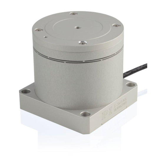
3 Product Description Product View Figure 1: Exemplary product view of an S-340 Platform Flexure Housing, consisting of 3a: Housing tube 3b: Base Protective earth connector D-Sub 25 connector Version: 3.0.1 PZ75E S340 Tip/Tilt Platform... -
Page 13: Product Labeling
3 Product Description Figure 2: S-340: Schematic view of the motion axes with positive direction of motion θ : Tilt axis 1 θ : Tilt axis 2 The arrows indicate the positive direction of motion of the respective axis. Product Labeling... - Page 14 3 Product Description Labeling of the Dsub 25 connector Figure 3: D-sub 25 connector on the connecting cable of the S-340 "Residual Voltage" warning sign: Indicates risk of electric shock (p. 5) Labeling of the S330.DLS adapter cable for S340.xSL Figure 4: S-330.DLS adapter cable: Piezo connectors [1] and sensor connectors [2]...
-
Page 15: Scope Of Delivery
2 flat washers PZ277EK Printed short instructions for S-3xx piezo tip/tilt platforms Additional scope of delivery of the S340.xxL models S-340.xSL models with position sensor: Product number Description S-330.DLS Adapter cable D-sub 25 to LEMO connectors for piezo tip/tilt mirrors / platforms, tilt axes with differential drive, with SGS S-340.x0L models without position sensor:... -
Page 16: Accessories
E-727.x • Digital multi-channel piezo controller E-727.xAP* * With E727B0015 adapter, D-sub 25 (f) to D-sub 37 (m) (included in the scope of delivery if you ordered the S-340 as system with E-727) Suitable electronics for the S340.xxL models Electronics Description E-500 •... - Page 17 1 to USB, and RS-232 modified for S-330, S-331, sensors, 3 channels 3 channels interfaces S-340 tip/tilt mirror systems, with a fixed voltage of +100 V, two variable voltages 2 × E-505.00 E-509.S3 E-500.00 Optional: E-518.I3...
-
Page 18: Control
Piezo actuator 2 of the axis Platform The S-340 is a tip/tilt platform with differential piezo drive. Four piezo actuators are interconnected in pairs to realize tip/tilt motion on two axes. Both pairs of actuators are electrically switched so that when piezo voltage U... -
Page 19: Dynamic Behavior
Most applications are not very sensitive to such deviations as long as the tip/tilt angle does not change. Each of the four piezo actuators of the S-340 is equipped with a strain gauge sensor. Therefore, in addition to the amplifier channel, a servo loop with a sensor channel must be available for each actuator pair. -
Page 20: Calculating Moments Of Inertia For Mirror And Mirror Holder
Axis through the center of gravity of the mirror Axis through the center of gravity of the mirror holder Mirror holder (example of a geometry) Axis through the pivot point of the platform of the S-340 ("rotational axis") Platform Version: 3.0.1 PZ75E S340 Tip/Tilt Platform... - Page 21 3 Product Description Figure 8: Example diagram: Platform with mirror holder and mirror; here with variables required for calculating the moments of inertia Distance from the axis through the center of gravity of the mirror to the rotational axis Distance from the axis through the center of gravity of the mirror holder to the rotational axis H/2 Half the mirror thickness Thickness of the mirror holder...
- Page 22 3 Product Description Calculating the moment of inertia of the mirror Formula for calculating the moment of inertia of a rotationally symmetric mirror: Formula for calculating the moment of inertia of a rectangular mirror: with: = Moment of inertia of the mirror, in relation to the rotational axis [g•mm = Mirror mass [g] R = Mirror radius [mm] = Mirror length perpendicular to the rotational axis [mm]...
-
Page 23: Calculating The Resonant Frequency Of The Tip/Tilt Platform
= Moment of inertia of the mirror holder, in relation to the rotational axis, [g•mm calculation see separate formula (p. 18) Further information on dynamic or static operation can be found in the PI catalog (CAT 130), in the section "Fundamentals of Piezo Technology". The catalog can be downloaded from our website http://www.pi.ws under Service >... -
Page 25: Unpacking
4 Unpacking Unpacking 1. Unpack the S-340 with care. 2. Compare the contents with the scope of delivery according to the contract and the delivery note. 3. Inspect the contents for signs of damage. If any parts are damaged or missing, contact our customer service department (p. -
Page 27: Installation
Install the S-340 so that the application is not impaired by the dissipated heat. Ensure sufficient ventilation at the place of installation. Make sure that the entire bottom of the S-340 is in contact with the surface on which the S-340 is mounted. - Page 28 Distorting the S340 when mounted on uneven surfaces! Fixing the S-340 onto an uneven surface can distort the S-340. Distortion reduces the accuracy. Fix the S-340 onto an even surface. The recommended flatness of the surface is ≤30 µm. For applications with large temperature fluctuations: Only fix the S-340 onto surfaces that have the same or similar thermal expansion properties as the S-340 (e.g., surfaces made of aluminum).
-
Page 29: Mounting The Mirror On The S-340
Despite its massive and robust appearance, the S-340 is a very sensitive and fragile system. The piezo actuators and joints can be damaged if the S-340 is allowed to fall or tip over. Do not allow the S-340 to fall or tip over. - Page 30 Make sure that the mirror and, if necessary, the mirror holder have the same or similar thermal expansion properties as the platform of the S-340. Prevent adhesive from penetrating the housing of the S-340 and running into the holes of the platform (see figure above).
- Page 31 S-340 tip/tilt platform Requirements You have read and understood the general notes on installation (p. 23). The S-340 is not connected to the electronics. Tools and accessories Suitable mirror, see above and "Dynamic Behavior" (p. 15) ...
- Page 32 If you use a template: Remove the template. 3. Fix the mirror to the platform: a) If you use a centering aid: Carefully align the centering aid on the S-340 and fix it appropriately. b) Place the mirror carefully in the appropriate orientation or into the centering aid on the platform of the S-340.
-
Page 33: Mounting The S-340
5 Installation Mounting the S340 Figure 12: Mounting holes in the base of the S-340 (view from above) Requirements You have read and understood the general notes on installation (p. 23). The S-340 is not connected to the electronics. -
Page 34: Connecting The S-340 To The Protective Earth Conductor
INFORMATION Pay attention to the applicable standards for connecting the protective earth conductor. The S-340 has an M4 hole for attaching the protective earth conductor. This hole is marked with the symbol for the protective earth conductor (see "Dimensions" (p. 46)). -
Page 35: Connecting The S-340 To The Electronics
1. If necessary, attach a suitable cable lug to the protective earth conductor. 2. Use the M4 screw (together with the flat and lock washers) to attach the cable lug of the protective earth conductor to the threaded hole in the S-340 as shown in the profile view. - Page 36 5 Installation Connecting the S340.xxD to the electronics 1. Connect the D-sub 25 connector of the S-340.xxD to the D-sub 25 socket of the electronics (refer to the user manual for the electronics). 2. Use the integrated screws to secure the connectors against accidental disconnection.
-
Page 37: Starting And Operating
If a protective earth conductor is not or not properly connected, dangerous touch voltages can occur on the S-340 in the case of malfunction or failure of the system. If there are touch voltages, touching the S-340 can result in minor injuries from electric shock. -
Page 38: Operating The S-340
Signals for Dynamic Operation" (p. 45) for details. INFORMATION Sound and vibration (e.g., footfall, knocks) can be transmitted to the S-340 and can affect its performance with regard to position stability. Avoid sound and vibration while the S-340 is being operated. -
Page 39: Discharging The S-340
The S-340 must be discharged in the following cases: Before Installation When the S-340 is not in use but the electronics remain switched on to ensure temperature stability Before demounting (e.g., before cleaning and transporting the S-340 and for ... -
Page 41: Maintenance
You have discharged the piezo actuators of the S-340 (p. 35). You have disconnected the S-340 from the electronics. Cleaning the S340 Clean the surfaces of the S-340 with a cloth dampened with a mild cleanser or disinfectant (e.g., isopropyl alcohol). S340 Tip/Tilt Platform PZ75E Version: 3.0.1... -
Page 43: Troubleshooting
Flatness of at least 30 μm The thermal expansion properties are similar to those of the S-340 (e.g., surfaces made of aluminum) Adhesive has run into the holes of Contact our customer service the platform or between the department (p. -
Page 45: Customer Service
9 Customer Service Customer Service For inquiries and orders, contact your PI sales engineer or send us an email (service@pi.de). If you have any questions concerning your system, provide the following information: Product and serial numbers of all products in the system −... -
Page 47: Technical Data
10 Technical Data Technical Data In this Chapter Specifications ..........................43 Dimensions ..........................46 Torque for Stainless Steel Screws (A2-70) ................... 48 Pin Assignment ..........................48 10.1 Specifications 10.1.1 Data Table S340.ASD / S340.ISD / S340.A0L S340.I0L Unit Tolerance S340.ASL S340.ISL Active axes θ... -
Page 48: Maximum Ratings
E-727 E-727 E-727 The resolution of the system is limited only by the noise of the amplifier and the measuring technology because PI piezo nanopositioning systems are free of friction. All specifications based on room temperature (22 °C ±3 °C). -
Page 49: Ambient Conditions And Classifications
10.1.4 Recommended Control Signals for Dynamic Operation The maximum permissible operating temperature for the piezo actuators of the S-340 is 80 °C. During dynamic continuous operation of a single axis, this temperature value is achieved at an ambient temperature of approx. 20 °C for the following characteristics of a sinusoidal piezo voltage signal and then remains constant. -
Page 50: Dimensions
10 Technical Data 10.2 Dimensions Figure 14: S-340.xxD, dimensions in mm. Note that the decimal places are separated by a comma in the drawings. Version: 3.0.1 PZ75E S340 Tip/Tilt Platform... - Page 51 10 Technical Data Figure 15: S-340.xxL, dimensions in mm. Note that the decimal places are separated by a comma in the drawings. S340 Tip/Tilt Platform PZ75E Version: 3.0.1...
-
Page 52: Torque For Stainless Steel Screws (A2-70)
10 Technical Data 10.3 Torque for Stainless Steel Screws (A270) Screw size Minimum torque Maximum torque 4 Nm 6 Nm 2.5 Nm 3.5 Nm 1.5 Nm 2.5 Nm 0.8 Nm 1.1 Nm M2.5 0.3 Nm 0.4 Nm 0.15 Nm 0.2 Nm M1.6 0.06 Nm 0.12 Nm... -
Page 53: S-330.Dlx Adapter Cable (Only For S-340.Xxl)
10 Technical Data Signal Function SGS Y- SGS signal axis 2 (negative) SGS GND Y Ground SGS signal axis 2 SGS X- SGS signal axis 1 (negative) SGS GND X Ground SGS signal axis 1 PZT GND Piezo voltage ground PZT GND Piezo voltage ground PZT GND... - Page 54 10 Technical Data Pin* Signal Function S330.DLS adapter cable for S330.DL0 adapter cable for S340.xSL S340.x0L PZT X Piezo voltage axis 1 Piezo voltage axis 1 PZT Y Piezo voltage axis 2 Piezo voltage axis 2 100 V fix 100 V fixed voltage 100 V fixed voltage SGS Y- SGS signal axis 2 (negative)
- Page 55 10 Technical Data Sensor connector (only S330.DLS adapter cable for S340.xSL) Figure 19: Sensor connector (SGS): LEMO FFA.0S.304.CLAC32Y connector, contact side Signal Function SGS Ref SGS reference SGS- SGS signal (negative) SGS+ SGS signal (positive) SGS GND Ground SGS signal S340 Tip/Tilt Platform PZ75E Version: 3.0.1...
-
Page 57: Old Equipment Disposal
Dispose of your old equipment according to international, national, and local rules and regulations. In order to fulfil its responsibility as the product manufacturer, Physik Instrumente (PI) GmbH & Co. KG undertakes environmentally correct disposal of all old PI equipment made available on the market after 13 August 2005 without charge. - Page 59 12 EU Declaration of Conformity EU Declaration of Conformity For the S-340, an EU Declaration of Conformity has been issued in accordance with the following European directives: Low Voltage Directive EMC Directive RoHS Directive The applied standards certifying the conformity are listed below.
Need help?
Do you have a question about the S-340 and is the answer not in the manual?
Questions and answers