Table of Contents
Advertisement
Quick Links
MP112E
U-628 Rotation Stage
User Manual
Version: 1.2.0
Date: 21.08.2015
This document describes the following
product:
U-628.03
PILine® rotation stage, >360° rotation
range, velocity 720°/s, incremental
encoder, 17 µrad resolution, 49 mm
diameter, piezoelectric ultrasonic motor
Physik Instrumente (PI) GmbH & Co. KG, Auf der Roemerstr. 1, 76228 Karlsruhe, Germany
Phone: +49 721 4846-0, Fax: +49 721 4846-1019, E-mail: info@pi.ws
Advertisement
Table of Contents

Related Manuals for PI U-628


Summary of Contents for PI U-628
- Page 1 PILine® rotation stage, >360° rotation range, velocity 720°/s, incremental encoder, 17 µrad resolution, 49 mm diameter, piezoelectric ultrasonic motor Physik Instrumente (PI) GmbH & Co. KG, Auf der Roemerstr. 1, 76228 Karlsruhe, Germany Phone: +49 721 4846-0, Fax: +49 721 4846-1019, E-mail: info@pi.ws...
- Page 2 Physik Instrumente (PI) GmbH & Co. KG is the owner of the following trademarks: PI®, PIC®, PICMA®, PILine®, PIFOC®, PiezoWalk®, NEXACT®, NEXLINE®, NanoCube®, NanoAutomation®, Picoactuator®, PInano®, PIMag® PI owns the following patents or patent applications for the technology field Ultrasonic Piezo Motors (PILine®):...
- Page 3 With regard thereto, Physik Instrumente (PI) GmbH & Co. KG retains all the rights. The use of any text, images and drawings is permitted only in part and only when indicating the source.
-
Page 5: Table Of Contents
ID Chip ....................13 Unpacking Installation General Notes on Installation ................17 Connecting the U-628 to the Protective Earth Conductor ........19 Mounting the U-628 on a Surface ..............21 Affixing the Load to the U-628 ................23 Start-Up and Operation General Notes on Start-Up and Operation ............25... - Page 6 Maintenance General Notes on Maintenance ................31 Performing a Maintenance Run ................31 Cleaning the U-628 .....................32 Troubleshooting Customer Service Technical Data 10.1 Specifications......................37 10.1.1 Data Table ..................37 10.1.2 Reference Point Switch Specifications ..........38 10.1.3 Maximum Ratings ................38 10.2 Ambient Conditions and Classifications .............39 10.3...
-
Page 7: About This Document
Downloading Manuals ....................3 1.1 Objective and Target Audience of this User Manual This manual contains information on the intended use of the U-628. It assumes that the reader has a fundamental understanding of basic servo systems as well as motion control concepts and applicable safety procedures. -
Page 8: Definition
Signals from the sensor are used for axis position feedback. After switching on the controller a reference point definition must be performed before absolute target positions can be commanded and reached. Version: 1.2.0 MP112E U-628 Rotation Stage... -
Page 9: Figures
For products that are supplied with software (CD in the scope of delivery), access to the manuals is protected by a password. Protected manuals are only displayed on the website after entering the password. The password is included on the CD of the product. U-628 Rotation Stage MP112E Version: 1.2.0... - Page 10 4. Find the user name and the password in the section "User login for software download" in the Release News. Downloading Manuals 1. Open the website http://www.pi.ws. 2. Click Info. 3. If you have a user name and password: a) Click Login.
-
Page 11: Safety
The U-628 is built according to state-of-the-art technology and recognized safety standards. Improper use can result in personal injury and/or damage to the U-628. Only use the U-628 for its intended purpose, and only use it if it is in a good working order. - Page 12 If a protective earth conductor is not or not properly connected, dangerous touch voltages can occur on the U-628 in the case of malfunction or failure of the system. If touch voltages exist, touching the U-628 can result in minor injuries from electric shock.
-
Page 13: Organizational Measures
Add all information from the manufacturer to the user manual, for example supplements or Technical Notes. If you give the U-628 on to other users, also include this user manual as well as other relevant information provided by the manufacturer. -
Page 15: Product Description
3.1 Product View Figure 1: U-628 product view Base body 0° mark: After a reference move of the U-628, the red point on the moving platform is above the 0° mark in the base body. Moving platform Cable for connecting to the controller Protective earth connection The arrow in the figure shows the positive direction of motion. -
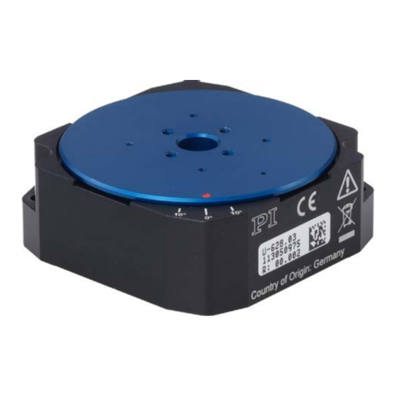
Page 16: Product Labeling
3 Product Description 3.2 Product Labeling Figure 2: U-628: Position of the product labeling (example view) Position Labeling Description Manufacturer's logo CE conformity mark Warning sign "Observe manual!" U-628.03 Product name 113050975 Serial number (example), individual for each U-628 Meaning of the places (counting from left):... -
Page 17: Scope Of Delivery
3 Product Description Figure 3: U-628: "Residual voltage" warning sign on connector Warning sign "Residual voltage": Notice of risk of electric shock (p. 5) 3.3 Scope of Delivery Item ID Components U-628.03 PILine® rotation stage, >360° rotation range, velocity 720°/s, incremental encoder, 17 µrad resolution, 49 mm diameter,... -
Page 18: Suitable Controllers
Extension cable for PILine®, 15-pin Sub-D, 3 m* U-600.A05 Extension cable for PILine®, 15-pin Sub-D, 5 m* * Other cable lengths available on request. To order, contact our customer service department (p. 35). Version: 1.2.0 MP112E U-628 Rotation Stage... -
Page 19: Technical Features
See the controller user manual and/or associated software manuals for the commands which make use of the reference point signal. After a reference move of the U-628, the red dot on the moving platform is above the 0° mark in the base body. -
Page 21: Unpacking
4 Unpacking Unpacking 1. Unpack the U-628 with care. 2. Compare the contents with the items listed in the contract and the packing list. 3. Inspect the contents for signs of damage. If parts are missing or you notice signs of damage, contact PI immediately. -
Page 23: Installation
Temperature changes can also induce charges in piezo actuators. Touching or short-circuiting the contacts in the connector of the U-628 can lead to minor injuries from electric shock. Do not touch the contacts in the connector of the U-628. - Page 24 Unsuitable cables can cause damage to the controller and affect the performance of the U-628. Only use genuine PI parts to connect the U-628 to the controller. If you need longer cables, use extension cables from PI (p. 12).
-
Page 25: Connecting The U-628 To The Protective Earth Conductor
Observe the applicable standards for mounting the protective earth conductor. On the U-628, there is an M4 hole next to the cable exit for connecting the protective earth conductor. In the following figure, this hole is marked with the symbol for the... - Page 26 2. Fasten the cable lug of the protective earth conductor using the M4 screw on the protective earth connection of the U-628 as shown in the profile view. 3. Tighten the M4 screw with a torque of 1.2 Nm to 1.5 Nm.
-
Page 27: Mounting The U-628 On A Surface
U-628 (e.g. surfaces made of aluminum). INFORMATION The positive direction of motion of the U-628 is shown in the product view (p. 9). Figure 6: Mounting holes for mounting the U-628 on a surface U-628 Rotation Stage MP112E Version: 1.2.0... - Page 28 Allen wrench AF 2.0 Mounting the U-628 on a Surface 1. Align the U-628 on the surface so that the corresponding holes in the U-628 (see arrows in the figure) and the surface overlap. 2. Put one flat washer on each screw.
-
Page 29: Affixing The Load To The U-628
NOTICE Screws that are too long! The U-628 can be damaged by screws that are too long. Note the depth of the mounting holes in the moving platform (p. 44). Only use screws of the correct length for the respective mounting holes. - Page 30 Suitable tools for tightening the screws Affixing the Load 1. Align the load on the U-628 so that the mounting holes in the load and the holes in the moving platform overlap. 2. Affix the load with at least three screws.
-
Page 31: Start-Up And Operation
If a protective earth conductor is not or not properly connected, dangerous touch voltages can occur on the U-628 in the case of malfunction or failure of the system. If touch voltages exist, touching the U-628 can result in minor injuries from electric shock. - Page 32 U-628. Only operate the U-628 with controllers/drivers and original accessories from PI. Do not exceed the operating voltage range (p. 38) for which the U-628 is specified. Only operate the U-628 when the operating voltage is properly connected; see "Pin Assignment"...
- Page 33 Observe the information in the "Motor Power" section (p. 40). INFORMATION Although in theory the U-628 operates quietly, noise levels of up to 50 dB (A) are possible during operation. The ultrasonic drive of the U-628 can also generate higher noise levels at frequencies between 100 and 500 kHz.
-
Page 34: Starting Up The U-628
If you use the software which is included in the scope of delivery of the controller (p. 12), the operating parameters of the U-628 can be loaded from a stage database. The PIStages2.dat stage database contains the default parameter values of your rotation stage for performing initial test motions during start-up. - Page 35 (p. 25). You have read and understood the user manual of the controller (p. 3). In the case of start-up with a load: The U-628 has been properly installed (p. 17). The controller (p. 12) and the required software have been installed. All connections on the controller have been set up (see controller manual).
-
Page 37: Maintenance
Depending on the operating conditions and the period of use of the U-628, a maintenance run may be required. The maintenance run is performed to redistribute the existing lubricant in the bearing of the U-628. The stage must rotate by at least one full revolution during the maintenance run. -
Page 38: Cleaning The U-628
7 Maintenance 7.3 Cleaning the U-628 Prerequisites You have disconnected the rotation stage from the controller. Cleaning the rotation stage When necessary, clean the rotation stage surface with a cloth lightly dampened with a mild cleanser or disinfectant. -
Page 39: Troubleshooting
See the controller user manual (p. 3) for details. Mount the U-628 on an even Increased wear Warped base body surface. The recommended Reduced accuracy evenness of the surface is 10 µm. - Page 40 (p. 37). Adjust the operating parameters The default parameter values according to the description in are not suitable for "Starting up the U-628". operating with high loads Adjust the operating parameters The default parameter values according to the description in are not suitable for "Starting up the U-628".
-
Page 41: Customer Service
9 Customer Service Customer Service For inquiries and orders, contact your PI sales engineer or send us an e-mail (info@pi.ws). If you have questions concerning your system, have the following information ready: − Product codes and serial numbers of all products in the system −... -
Page 43: Technical Data
Mechanical Properties Load capacity / axial force max. Holding torque 0.03 max. Torque cw / ccw (θ 0.025 max. Drive Properties Motor type PILine® ultrasonic piezomotor, performance class 1 Reference point switch Optical U-628 Rotation Stage MP112E Version: 1.2.0... -
Page 44: Reference Point Switch Specifications
Type Optical sensor Supply voltage +5 V/GND, supply via the motor connector Signal output TTL level 10.1.3 Maximum Ratings The U-628 rotation stages are designed for the following operating data: Maximum Operating Operating Frequency Maximum Power Voltage Consumption 160 V... -
Page 45: Ambient Conditions And Classifications
10 Technical Data 10.2 Ambient Conditions and Classifications The following ambient conditions and classifications must be observed for the U-628: Area of application For indoor use only Maximum altitude 2000 m Air pressure 1100 hPa to 0.1 hPa (corresponds to roughly 825 torr to 0.075 torr) -
Page 46: Motor Power
INFORMATION The operating voltage is limited by the controller using the Maximum Motor Output (V) (ID 0x7c) parameter. If you load the operating parameters of the U-628 from the PIStages2.dat stage database, the parameter is set to the maximum permissible value. -
Page 47: Velocity And Torque
10 Technical Data 10.3.2 Velocity and Torque The following figure can be used to estimate the velocity and torque of the U-628 with different motor powers. Motion is possible starting at a motor power of approx. 30 %. Figure 8: Relationship between velocity and torque of the U-628 with different motor power levels... -
Page 48: Motor Power And Lifetime
(break). The motor should only sporadically be operated at peak power; the peak power serves as a control reserve. Figure 9: U-628: Recommended duty cycle and motor power depending on the ambient temperature Version: 1.2.0 MP112E... -
Page 49: Influence Of Downtimes On The Torque
10 Technical Data 10.3.4 Influence of Downtimes on the Torque Figure 10: Torque of the U-628 depending on the downtime of the motor U-628 Rotation Stage MP112E Version: 1.2.0... -
Page 50: Dimensions
10 Technical Data 10.4 Dimensions Dimensions in mm. Note that the decimal places are separated by a comma in the drawings. Figure 11: U-628, moving platform in reference position Version: 1.2.0 MP112E U-628 Rotation Stage... -
Page 51: Pin Assignment
Output: Encoder channel B (inverted), RS-422 USM_P1 Input: Piezo 57 VAC (RMS) USM_P3 Input: Piezo 57 VAC (RMS) Not connected REFSWITCH Output: Reference point switch ENCA+ Output: Encoder channel A, RS-422 ENCB+ Output: Encoder channel B, RS-422 U-628 Rotation Stage MP112E Version: 1.2.0... -
Page 53: Old Equipment Disposal
GmbH & Co. KG undertakes environmentally correct disposal of all old PI equipment made available on the market after 13 August 2005 without charge. Any old PI equipment can be sent free of charge to the following address: Physik Instrumente (PI) GmbH & Co. KG Auf der Roemerstr. - Page 55 12 EC Declaration of Conformity 12 EC Declaration of Conformity For the U-628, an EC Declaration of Conformity has been issued in accordance with the following European directives: 2006/95/EC, Low Voltage Directive 2004/108/EC, EMC Directive 2011/65/EU, RoHS Directive The applied standards certifying the conformity are listed below.
Need help?
Do you have a question about the U-628 and is the answer not in the manual?
Questions and answers