Table of Contents
Advertisement
Quick Links
MP150E
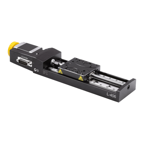
L-406 Compact Linear Stage
User Manual
Version: 1.1.0
Physik Instrumente (PI) GmbH & Co. KG, Auf der Roemerstrasse 1, 76228 Karlsruhe, Germany
Phone +49 721 4846-0, Fax +49 721 4846-1019, Email info@pi.ws, www.pi.ws
Date: 26.06.2020
This document describes the following products:
L-406.x0DG10:
With DC gear motor and rotary encoder
L-406.x0DD10:
With DC motor and rotary encoder
L-406.x0SD00:
with 2-phase stepper motor, without encoder
x stands for travel range:
1 = 26 mm
2 = 52 mm
4 = 102 mm
Advertisement
Table of Contents

Related Manuals for PI L-406 Series


Summary of Contents for PI L-406 Series
- Page 1 1 = 26 mm 2 = 52 mm 4 = 102 mm Physik Instrumente (PI) GmbH & Co. KG, Auf der Roemerstrasse 1, 76228 Karlsruhe, Germany Phone +49 721 4846-0, Fax +49 721 4846-1019, Email info@pi.ws, www.pi.ws...
- Page 2 BiSS is a registered trademark of iC-Haus GmbH. © 2020 Physik Instrumente (PI) GmbH & Co. KG, Karlsruhe, Germany. The text, photographs, and drawings in this manual are protected by copyright. With regard thereto, Physik Instrumente (PI) GmbH & Co. KG retains all the rights.
-
Page 3: Table Of Contents
Contents About this Document Objective and Target Audience of this User Manual..........1 Other Applicable Documents ..................1 Symbols and Typographic Conventions..............1 Figures ........................2 Downloading Manuals ....................3 Safety Intended Use ......................5 General Safety Instructions ..................5 Organizational Measures .................... - Page 4 Startup General Notes on Startup ..................31 Starting and Operating the L-406 ................33 L-406 Entries in the PI Positioner Database ............. 33 6.3.1 Operating Parameters of the Models with DC Motor ......... 33 6.3.2 Operating Parameters of the Models with Stepper Motor ......34 Maintenance General Notes on Maintenance ................
-
Page 5: About This Document
The latest versions of the user manuals are available for download (p. 3) on our website. Other Applicable Documents The devices and software tools from PI mentioned in this documentation are described in separate manuals. Product... -
Page 6: Figures
1 About this Document NOTICE Dangerous situation Failure to comply could cause damage to equipment. Precautionary measures for avoiding the risk. INFORMATION Information for easier handling, tricks, tips, etc. Symbol/ Meaning Label Action consisting of several steps whose sequential order must be observed Action consisting of one or several steps whose ... -
Page 7: Downloading Manuals
If a manual is missing or problems occur with downloading: Contact our customer service department (p. 41). Downloading manuals 1. Open the website www.pi.ws. 2. Search the website for the product number (e.g., P-882) or the product family (e.g., PICMA® bender). -
Page 9: Safety
2 Safety Safety Intended Use The L-406 is a laboratory device as defined by DIN EN 61010. It is intended for indoor use and use in an environment that is free of dirt, oil and lubricants. In accordance with its design, the L-406 is intended for single-axis positioning, adjusting and shifting of loads at different velocities. -
Page 10: Organizational Measures
2 Safety Organizational Measures User manual Always keep this user manual together with the L-406. The latest versions of the user manuals are available for download (p. 3) on our website. Add all information from the manufacturer to the user manual, for example supplements or technical notes. -
Page 11: Product Description
3 Product Description Product Description Model Overview Order number Product name L-406.10DG10 Compact linear stage, 65 mm width, DC gear motor, 26 mm travel range, optical limit switches L-406.10DD10 Compact linear stage, 65 mm width, DC motor, 26 mm travel range, optical limit switches L-406.10SD00 Compact linear stage, 65 mm width, stepper motor, 26 mm travel range,... -
Page 12: Product View
3 Product Description Product View Figure 1: Parts of the L-406 with DC motor / DC gear motor (above), L-406 with stepper motor (below) Motor Drive screw Motion platform Base body Motor connector (HD D-sub 26 panel plug) Vibration absorber Version: 1.1.0 MP150E L-406 Compact Linear Stage... -
Page 13: Direction Of Motion
3 Product Description Direction of Motion Figure 2: Direction of motion of the motion platform (arrow direction:) Direction of motion on positive command Product Labeling Figure 3: Product labeling L-406 Compact Linear Stage MP150E Version: 1.1.0... -
Page 14: Scope Of Delivery
Meaning of each position (from the left): 1 = internal information, 2 and 3 = year of manufacture, 4 to 9 = consecutive number CE conformity mark WWW.PI.WS Manufacturer's address (website) Warning sign "Pay attention to the manual!" 2, 3... -
Page 15: Accessories
Controller for DC motors, 4 / 6 axes, USB, RS-232, Ethernet, SPI, I/O, joystick connection The required PC software is included in the scope of delivery of the controllers from PI. The operation of the controllers is described in the corresponding user manuals. -
Page 16: Technical Features
3 Product Description Technical Features 3.8.1 Rotary Encoder The L-406.x0DG10 and L-406.x0DD10 models are equipped with an incremental rotary encoder. A rotary encoder is implemented at a rotating point in the drivetrain, e.g., the motor shaft. 3.8.2 Limit Switches The L-406 is equipped with optical limit switches. Each limit switch sends its signal to the controller on a dedicated line. -
Page 17: Unpacking
3. Compare the contents with the items listed in the contract and the packing list. 4. Inspect the contents for signs of damage. If there is any sign of damage or missing parts, contact PI immediately. 5. Keep all packaging materials and the ESD protection in case the product needs to be returned. -
Page 19: Installation
5 Installation Installation General Notes on Installation NOTICE Unwanted changes in position when mounted vertically! If the load exceeds the holding force of the L-406 when the drive is mounted vertically, unwanted changes in the position of the platform will occur. Unwanted changes in the position of the platform can damage the drive, the load or the surroundings. -
Page 20: Mounting The L-406 Onto A Surface
5 Installation INFORMATION The use of locating pins during mounting reduces deviations from the ideal alignment of the L- 406. If possible, simulate the positioner motions with a mounted load or make suitable calculations to detect collisions or unfavorable center of gravity constellations. ... - Page 21 5 Installation Position of the holes for alignment and mounting of the L-406 (bottom; dark arrows: Mounting holes, long light arrows respectively: Locating holes 3 mm, short light arrows: Locating holes 4 mm) L-406.1xxxxx models (example L- L-406.2xxxxx and L-406.4xxxxx models 406.10SD00) (example L-406.40SD00) Requirements...
-
Page 22: Connecting The L-406 To The Protective Earth Conductor
5 Installation Tools and accessories Mounting kit, included in the scope of delivery (p. 10) − 4 or 8 socket head screws, ISO 4762 - M4x12 − Optional: 2 dowel pins, ISO 2338 - 4h8x10 or 3h8x6 for use as locating pins Hex key, AF 3 ... - Page 23 5 Installation There is an M4 hole in the base body of the L-406 for the protective earth conductor connection. In the following figure, this hole is marked with an arrow. Figure 4: Position of the hole for attaching the protective earth conductor Figure 5: Connecting the protective earth conductor (profile view) Base body of the L-406 Flat washer...
-
Page 24: Fixing The Load To The L-406
5 Installation Connecting the L-406 to the protective earth conductor 1. If necessary, attach a suitable cable lug to the protective earth conductor. 2. Use the M4 screw (together with the flat and lock washers) to attach the cable lug of the protective earth conductor to the threaded hole in the L-406 as shown in the profile view. - Page 25 5 Installation − If you use locating pins for aligning the load: You have drilled two locating holes with Ø 3 mm into the load to accommodate the locating pins. Tools and accessories At least 2 screws of suitable length. Options: ...
-
Page 26: Building A Multi-Axis System
5 Installation Building a Multi-Axis System The L-406 can be used in multi-axis systems. Typical combinations: XY system (p. 22) Z system (XZ or XYZ combination) (p. 25) Contact our customer service department (p. 41) for possible combinations with other positioners. - Page 27 5 Installation Lower positioner: Forms the basis of the multi-axis system (X axis), is attached to an underlying surface Upper positioner: Forms the Y axis of the multi-axis system, is attached to the lower positioner rotated by 90° Examples of XY systems consisting of two L-406 Requirements ...
- Page 28 5 Installation Building an XY System Figure 6: Moving the motion platform and mounting the screws and locating pins Lower positioner Upper positioner M4x12 screw Locating pin 3h8x6 1. If you use locating pins to align the upper positioner: a) Insert the two locating pins into the locating holes in the platform of the lower L- 406 (see figure above).
-
Page 29: Setting Up A Z System
5 Installation 3. Fix the L-406 to the mounting hole made accessible on the lower L-406: Tighten the screw in the mounting hole completely. 4. Repeat steps 2 and 3 for the other mounting holes required in the base body of the upper positioner. - Page 30 5 Installation Figure 7: Example of an XZ system consisting of two L-406 and an adapter bracket Lower positioner Upper positioner Adapter bracket Requirements You have read and understood the general notes on installation (p. 15). You have read and understood the general notes on setting up a multi-axis system (p. 22).
- Page 31 5 Installation Mounting kit from the scope of delivery of the adapter bracket: − 2 socket head cap screws, ISO 4762 M6x12 Hex key, AF 3 Hex key, AF 5 Building a Z system Figure 8: Mounting the adapter bracket (left) and the upper stage (right) Lower positioner Locating pin 3h8x6 Adapter bracket...
-
Page 32: Connecting The L-406 To The Controller
5 Installation b) Put the short side of the adapter bracket on the platform of the lower positioner so that the locating pins are inserted into the corresponding locating holes in the platform. c) Fix the adapter bracket to the positioner with two M6x12 screws. 2. - Page 33 5 Installation Connecting the L-406 to the controller 1. Remove the ESD protection from the L-406's connector. 2. Connect the L-406, cable, and controller to each other. 3. Use the integrated screws to secure the connections against accidental disconnection. L-406 Compact Linear Stage MP150E Version: 1.1.0...
-
Page 35: Startup
6 Startup Startup General Notes on Startup CAUTION Risk of crushing by moving parts! There is a risk of minor injuries from crushing between the moving parts of the positioner or the load and a fixed part or obstacle. Use protective structures to keep limbs away from areas in which they could be caught by moving parts. - Page 36 INFORMATION The repeatability of the positioning is only ensured when the reference switch is always approached from the same side. Controllers from PI fulfill this requirement due to the automatic direction sensing for reference moves to the reference switch. For L-406.x0DD10 and L-406.x0DG10 models: INFORMATION Improper setting of the servo control parameters can impair the performance of the L-406.
-
Page 37: Starting And Operating The L-406
Configure the controller during startup using the PC software for the L-406 used (see the user manual for the controller, and the PC software): − If you use a PI controller: Select the correct entry from the positioner database that fits (p. 33) the model of the L-406 exactly. −... -
Page 38: Operating Parameters Of The Models With Stepper Motor
6 Startup Parameter L-406.x0DD10 L-406.x0DG10 Unit D term I limit 2000 2000 Maximum acceleration mm/s² Maximum velocity* mm/s Maximum velocity* 81920 182120 counts/s Gear ratio 2401:81 Encoder resolution 1024 15176.69 counts/mm Limit switch polarity Active high Active high * Recommended for continuous operation 6.3.2 Operating Parameters of the Models with Stepper Motor If you use a stepper motor controller from a third-party supplier, it may be necessary to enter... -
Page 39: Maintenance
7 Maintenance Maintenance General Notes on Maintenance NOTICE Damage due to improper maintenance! Improper maintenance can lead to misalignment and failure of the L-406. Only loosen screws according to the instructions in this manual. Performing a Maintenance Run Depending on the operating conditions and the period of use of the L-406, the following maintenance measures are required: Maintenance run The maintenance run serves the purpose of distributing the existing lubricant. -
Page 40: Cleaning The L-406
7 Maintenance Cleaning the L-406 Requirements You have disconnected the positioner from the controller. Cleaning the positioner When necessary, clean the surface of the positioner with a cloth dampened lightly with a mild cleanser or disinfectant. Moving the Motion Platform Manually INFORMATION In the following cases, it can be necessary to manually move the platform: ... - Page 41 7 Maintenance Figure 10: Position of the vibration absorber (L-406.x0SD00 models only) Requirements The L-406 is not connected to the controller. Tools If you want to use the drive screw access: Hex key AF 3 Moving the Platform by Hand If you want to use the drive screw access: 1.
-
Page 43: Troubleshooting
Increased wear due to small Perform a maintenance run over the motion over a long period of entire travel range (p. 35). time Function impairment Controller from PI: Controller was replaced. after system Load the parameters from the positioner ... - Page 44 Software for the affected axis. Refer to the user manual for the controller for details. Platform has triggered the If you use a controller from PI: limit switch. 1. Switch the servo mode on in the PC software for the affected axis again.
-
Page 45: Customer Service
9 Customer Service Customer Service For inquiries and orders, contact your PI sales engineer or send us an email (mailto:service@pi.de). If you have any questions concerning your system, provide the following information: − Product and serial numbers of all products in the system −... -
Page 47: Technical Data
10 Technical Data Technical Data 10.1 Specifications 10.1.1 Data Table L-406.x0DD10 L-406.x0DG10 L-406.x0SD00 Unit Tole- rance Linear stage with DC Linear stage with DC Linear stage with motor and rotary gear motor and stepper motor encoder rotary encoder Active axis Motion and positioning L-406.x0DD10 L-406.x0DG10 L-406.x0SD00... - Page 48 10 Technical Data Mechanical properties L-406.x0DD10 L-406.x0DG10 L-406.x0SD00 Unit Tole- rance Guide type Recirculating ball Recirculating ball Recirculating ball bearing guide bearing guide bearing guide Drive screw type Leadscrew Leadscrew Leadscrew Drive screw pitch Gear ratio – 2401:81 – Load capacity Max.
-
Page 49: Maximum Ratings
10 Technical Data Miscellaneous L-406.x0DD10 L-406.x0DG10 L-406.x0SD00 Unit Tole- rance ACS modular ACS modular 663.12C885 (up to controller controller 20 axes) ACS modular controller 10.1.2 Maximum Ratings The L-406 positioners are designed for the following operating data: Maximum operating Maximum power Product Operating frequency voltage... -
Page 50: Limit Switch Specifications
10 Technical Data 10.1.4 Limit Switch Specifications Type Optical sensor Supply voltage +5 V / ground Signal output TTL level Signal logic The signal level changes when passing the limit switch. The signal logic is active high. That means: Normal motor operation: low (0 V) ... - Page 51 10 Technical Data Figure 11: L-406.x0DG10 and L-406.x0DD10 models Model L-406.10DD10, L-406.10DG10 55.5 73.5 62.5 L-406.20DD10, L-406.20DG10 68.5 73.5 75.5 L-406.40DD10, L-406.40DG10 93.5 73.5 75.5 L-406 Compact Linear Stage MP150E Version: 1.1.0...
-
Page 52: L-406.X0Sd00
10 Technical Data 10.2.2 L-406.x0SD00 Dimensions in mm. Note that a comma is used in the drawings instead of a decimal point. See "Hole Pattern of the Platform of the L-406" (p. 49) for a detailed view of the platform. Figure 12: L-406.x0SD00 models Model L-406.10SD00... -
Page 53: Hole Pattern Of The Moving Platform Of The L-406
10 Technical Data 10.2.3 Hole Pattern of the Moving Platform of the L-406 Dimensions in mm. Note that a comma is used in the drawings instead of a decimal point. Figure 13: Hole Pattern of the Motion Platform L-406 Compact Linear Stage MP150E Version: 1.1.0... -
Page 54: L-500.Av3 Adapter Bracket
10 Technical Data 10.2.4 L-500.AV3 Adapter Bracket Dimensions in mm. Note that a comma is used in the drawings instead of a decimal point. Figure 14: L-500.AV3 adapter bracket Version: 1.1.0 MP150E L-406 Compact Linear Stage... -
Page 55: Tightening Torque For Screws, Iso 4762 - A2
10 Technical Data Figure 15: L-500.AV3 adapter bracket 10.3 Tightening Torque for Screws, ISO 4762 - A2 The following tightening torques for screws according to ISO 4762 (corresponds to DIN 912) - A2 may not be exceeded. Value Maximum tightening torque 1.5 Nm 2 Nm 2.5 Nm... -
Page 56: Pin Assignment
10 Technical Data 10.4 Pin Assignment 10.4.1 HD D-sub 26 (m) Figure 16: HD Sub-D 26 panel plug Pin assignment for L-406.x0SD00 models Signal Direction Motor A+ Input Motor A+ Input Motor A- Input Motor A- Input Motor B+ Input Motor B+ Input Motor B-... - Page 57 10 Technical Data Signal Direction GND (limit) Pin assignment for L-406.x0DG10 and L-406.x0DD10 models Signal Direction Motor + Input Motor + Input Motor - Input Motor - Input Output Limit E1 (neg) Output Limit E2 (pos) Output ID I/O Bidirectional Limit Power (+5 V) Input Encoder A+...
-
Page 59: Old Equipment Disposal
PI miCos equipment made available on the market after 13 August 2005 without charge. Any old PI miCos equipment can be sent free of charge to the following address: PI miCos GmbH Freiburger Strasse 30... - Page 61 12 EU Declaration of Conformity EU Declaration of Conformity For the L-406, an EU Declaration of Conformity has been issued in accordance with the following European directives: EMC Directive RoHS Directive The applied standards certifying the conformity are listed below. EMC: EN 61326-1 Safety: EN 61010-1 RoHS: EN 50581 or EN IEC 63000...
Need help?
Do you have a question about the L-406 Series and is the answer not in the manual?
Questions and answers