Table of Contents
Advertisement
Quick Links
Advertisement
Table of Contents

Related Manuals for Supermicro SuperServer 5019C-WR


Summary of Contents for Supermicro SuperServer 5019C-WR
- Page 1 SuperServer ® 5019C-WR USER’S MANUAL Revision 1.0...
- Page 2 State of California, USA. The State of California, County of Santa Clara shall be the exclusive venue for the resolution of any such disputes. Supermicro's total liability for all claims will not exceed the price paid for the hardware product.
- Page 3 About this Manual This manual is written for professional system integrators and PC technicians. It provides information for the installation and use of the SuperServer 5019C-WR. Installation and maintainance should be performed by experienced technicians only. Please refer to the 5019C-WR server specifications page on our website for updates on supported memory, processors and operating systems (http://www.supermicro.com).
-
Page 4: Table Of Contents
Preface Contents Chapter 1 Introduction 1.1 Overview ..........................8 1.2 Unpacking the System ......................8 1.3 System Features ........................9 1.4 Server Chassis Features ....................10 Control Panel ........................10 Front Features ........................11 Rear Features ........................12 1.5 Motherboard Layout ......................13 Quick Reference Table ......................14 Chapter 2 Server Installation 2.1 Overview ..........................17 2.2 Preparing for Setup ......................17 Choosing a Setup Location ....................17... - Page 5 SuperServer 5019C-WR User's Manual Processor and Heatsink Installation ..................25 Memory Installation ......................29 Memory Support ......................29 General Guidelines for Optimizing Memory Performance ..........29 DIMM Installation ......................30 PCI Expansion Card Installation ..................31 DIMM Removal .........................31 Motherboard Battery ......................32 3.4 Chassis Components ......................33 Front Bezel ........................33...
- Page 6 Preface Chapter 6 BIOS 6.1 Introduction .........................60 6.2 Main Setup .........................61 6.3 Advanced Setup Configurations ..................63 6.4 Event Logs .........................86 6.5 IPMI ........................... 88 6.6 Security ..........................91 6.7 Boot ...........................95 6.8 Save & Exit .........................99 Appendix A BIOS Error Codes Appendix B Standardized Warning Statements for AC Systems Appendix C System Specifications...
- Page 7 Super Micro Computer, Inc. 980 Rock Ave. San Jose, CA 95131 U.S.A. Tel: +1 (408) 503-8000 Fax: +1 (408) 503-8008 Email: marketing@supermicro.com (General Information) support@supermicro.com (Technical Support) Website: www.supermicro.com Europe Address: Super Micro Computer B.V. Het Sterrenbeeld 28, 5215 ML...
-
Page 8: Overview
Rack Rail Mounting Kit MCP-290-00054-0N 1.2 Unpacking the System Inspect the box the SuperServer 5019C-WR was shipped in and note if it was damaged in any way. If any equipment appears damaged, please file a damage claim with the carrier who delivered it. -
Page 9: System Features
Chapter 1: Introduction 1.3 System Features The following table provides you with an overview of the main features of the 5019C-WR. Please refer to Appendix C for additional specifications. System Features Motherboard X11SCW-F Chassis SC815TQC-R504WB2 Intel Xeon E-2100, 8th Generation Core i3, Pentium, and Celeron series processor with six cores and a thermal design power (TDP) of up to 95W Socket Type LGA1151 (H4) -
Page 10: Server Chassis Features
SuperServer 5019C-WR User's Manual 1.4 Server Chassis Features Control Panel The switches and LEDs located on the control panel are described below. See Chapter 4 for details on the control panel connections. Figure 1-1. Control Panel View Control Panel Features... -
Page 11: Front Features
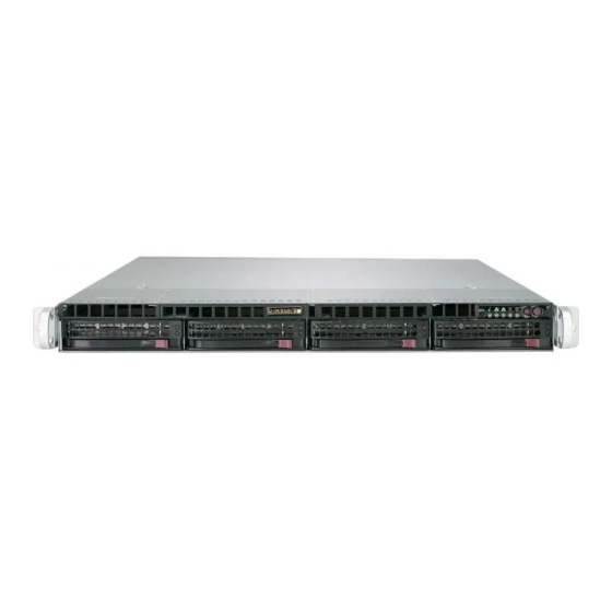
Chapter 1: Introduction Front Features The 5019C-WR is a 1U system. See the illustration below for the features included on the front of the chassis. Figure 1-2. Chassis Front View Front Chassis Features Item Feature Description Hard Drive Carrier Carrier for hot-swap hard drive Slim FDD Bay/USB/COM Slim Fixed Disk Drive/USB/COM port tray (Optional) Port Tray... -
Page 12: Rear Features
SuperServer 5019C-WR User's Manual Rear Features The illustration below shows the features included on the rear of the chassis. Figure 1-3. Chassis Rear View Rear Chassis Features Item Feature Description Power Supply 500W Platinum Level Power Supply (p/n PWS-504P-1R) I/O Back Panel Rear I/O ports (see Section 4.3) -
Page 13: Motherboard Layout
Chapter 1: Introduction 1.5 Motherboard Layout Below is a layout of the X11SCW-F with jumper, connector and LED locations shown. See the table on the following page for descriptions. For detailed descriptions, pinout information and jumper settings, refer to Chapter 4. USB6/7 (3.1) JPG1 COM1... -
Page 14: Quick Reference Table
SuperServer 5019C-WR User's Manual Quick Reference Table Jumper Description Default Setting JBT1 CMOS Clear Open (Normal) JPG1 VGA Enable Pins 1-2 (Enabled) JPL1, JPL2 LAN1, LAN2 Enable Pins 1-2 (Enabled) JPME2 ME Manufacturing Mode Pins 1-2 (Normal) JWD1 Watchdog Timer... - Page 15 Chapter 1: Introduction Connector Description M.2 Slot for PCI-E 3.0 x4 or SATA 3.0 M.2-H_1 (Supports M-Key 2260 / 2280 / 22110 FF and Intel Optane Memory) M.2 Slot for PCI-E 3.0 x4 M.2-P_2 (Supports M-Key 2260 / 2280 / 22110 FF and Intel Optane Memory) JSXB1A, JSXB1B, SMC-Proprietary WIO_L (Left) Add-On Card Slot JSXB1C...
- Page 16 SuperServer 5019C-WR User's Manual IMVP 8 #B-1 6 PHASE for Vcore #B-0 #A-1 #A-0 PCI-E X16 8.0 Gb/S Skt-H4 SXB1 PCIe 3.0 x16 #0-15 LGA1151 DMI3 DMI3 x4 PCI-E X4 8.0 Gb/S PCIe3.0 x4 (in x16) SXB2 #1/2/3/4 PCI-E X1 2.5 Gb/S PCI-E X4 8.0 Gb/S...
-
Page 17: Chapter 2 Server Installation
Chapter 2: Server Installation Chapter 2 Server Installation 2.1 Overview This chapter provides advice and instructions for mounting your system in a server rack. If your system is not already fully integrated with processors, system memory etc., refer to Chapter 4 for details on installing those specific components. Caution: Electrostatic Discharge (ESD) can damage electronic components. -
Page 18: Server Precautions
SuperServer 5019C-WR User's Manual • In single rack installations, stabilizers should be attached to the rack. In multiple rack in- stallations, the racks should be coupled together. • Always make sure the rack is stable before extending a server or other component from the rack. -
Page 19: Circuit Overloading
Chapter 2: Server Installation Circuit Overloading Consideration should be given to the connection of the equipment to the power supply circuitry and the effect that any possible overloading of circuits might have on overcurrent protection and power supply wiring. Appropriate consideration of equipment nameplate ratings should be used when addressing this concern. -
Page 20: Installing The Rails
SuperServer 5019C-WR User's Manual 2.3 Installing the Rails There are a variety of rack units on the market, which may require a slightly different assembly procedure. The following is a basic guideline for installing the system into a rack with the rack mounting hardware provided. -
Page 21: Installing The Outer Rails
Chapter 2: Server Installation Installing the Outer Rails Begin by measuring the distance from the front rail to the rear rail of the rack. Attach a short bracket to the front side of the right outer rail and a long bracket to the rear side of the right outer rail. -
Page 22: Installing The Server Into A Rack
SuperServer 5019C-WR User's Manual 2.4 Installing the Server into a Rack Installing to a Standard Rack You should now have rails attached to both the chassis and the rack. The next step is to install the server into the rack. -
Page 23: Installing To A Telco Rack
Chapter 2: Server Installation Installing to a Telco Rack To install the SuperServer 5019C-WR into a Telco (or “open”) type rack, use two L-shaped brackets on either side of the chassis (four total). 1. First, determine how far the server will extend out from the front of the rack. The chassis should be positioned so that the weight is balanced between front and back. -
Page 24: Chapter 3 Maintenance And Component Installation
SuperServer 5019C-WR User's Manual Chapter 3 Maintenance and Component Installation This chapter provides instructions on installing and replacing main system components. To prevent compatibility issues, only use components that match the specifications and/or part numbers given. Installation or replacement of most components require that power first be removed from the system. -
Page 25: Motherboard Components
CPU socket cap is in place and none of the socket pins are bent; otherwise, contact your retailer immediately. • Refer to the Supermicro website for updates on CPU support. Installing the Processor(s) Begin by removing power from the system as described in Section 3.1. - Page 26 SuperServer 5019C-WR User's Manual Top Edge Bottom Edge Figure 3-2. Placing the Processor into the Socket 3. Use your thumb and your index finger to hold the edges of the processor. Align the CPU key (the semi-circle cutouts) with the socket keys.
- Page 27 Chapter 3: Maintenance and Component Installation Installing a Heatsink A passive type heatsink is used on the X11SCW-F. Note: Do not apply any thermal grease to the heatsink or the CPU die; the required amount has already been applied. 1. Place the heatsink on top of the CPU so that the four mounting holes are aligned with those on the heatsink retention mechanism.
- Page 28 SuperServer 5019C-WR User's Manual Removing a Heatsink We do not recommend removing the heatsink. If necessary, please follow the instructions below to prevent damage to the CPU or the CPU socket. 1. Unscrew and remove the heatsink screws from the motherboard in the sequence as show in the figure above.
-
Page 29: Memory Installation
(2-DIMM per channel) with speeds of up to 2666MHz in four memory slots. Refer to the tables below for the recommended DIMM population order and additional memory information. Note: Check the Supermicro website for possible updates to memory support. Exercise extreme caution when installing or removing memory modules to prevent any possible damage to the DIMMs or slots. -
Page 30: Dimm Installation
SRW2 SRW3 SuperServer 5019C-WR User's Manual Intel 2280 2280 C246 SRW1 SRW4 2260 2260 IPMI CODE MAC CODE JSTBY1 BAR CODE M.2-P_2 M.2-H_1 I-SGPIO2 I-SGPIO1 BIOS LICENSE FAIL LEDPWR FAN2 FAN1 DIMMA1 DIMMA2 DIMMB1 DIMMB2 DIMM Installation 1. Insert the desired number of DIMMs... -
Page 31: Pci Expansion Card Installation
Chapter 3: Maintenance and Component Installation DIMM Removal Press both release tabs on the ends of the DIMM socket to unlock it. Once the DIMM module is loosened, remove it from the memory slot. PCI Expansion Card Installation The system includes two pre-installed riser cards: RSC-R1UW-E8R, for a standard size PCI-E x4 card in a x8 slot, and RSC-W-68, which supports 2x PCI-E x8 or one PCI-E x16 cards (with a jumper, see following page). -
Page 32: Motherboard Battery
SuperServer 5019C-WR User's Manual Motherboard Battery The motherboard uses non-volatile memory to retain system information when system power is removed. This memory is powered by a lithium battery residing on the motherboard. Replacing the Battery Begin by removing power from the system as described in section 3.1. -
Page 33: Chassis Components
Chapter 3: Maintenance and Component Installation 3.4 Chassis Components Front Bezel If your system has an optional bezel attached to the front of the chassis, you will need to remove it to gain access to the drive bays. 1. Unlock the front of the chassis and then press the release knob. 2. -
Page 34: Hard Drive Carrier Indicators
Note: Refer to the following FTP site for RAID setup guidelines: <ftp://ftp.supermicro.com/ driver/SAS/LSI/LSI_SAS_EmbMRAID_SWUG.pdf> and Supermicro’s web site for additional information < http://www.supermicro.com/support/manuals/>. Hard Drive Carrier Indicators Each hard drive carrier has two LED indicators: an activity indicator and a status indicator. In RAID configurations, the status indicator lights to indicate the status of the drive. - Page 35 Chapter 3: Maintenance and Component Installation Figure 3-9. Mounting a Drive in a Carrier Figure 3-10. Removing a Drive Carrier Note: Enterprise level hard disk drives are recommended for use in Supermicro chassis and servers. For information on recommended HDDs, visit the Supermicro website.
-
Page 36: Dvd-Rom Drive Installation
SuperServer 5019C-WR User's Manual DVD-ROM Drive Installation The 5019C-WR can accommodate a slim DVD drive (optional). Side mounting brackets are needed to install the DVD drive in the chassis. Accessing a DVD-ROM Drive Begin by removing power from the system as described in Section 3.1. - Page 37 Chapter 3: Maintenance and Component Installation 5. Place the new fan into the vacant space in the housing while making sure the arrows on the top of the fan (indicating air direction) point in the same direction as the arrows on the other fans.
-
Page 38: Power Supply
SuperServer 5019C-WR User's Manual Power Supply The 5019C-WR chassis comes equipped with two redundant 500 Watt hot-plug power supplies. These power supplies are auto-switching capable and automatically sense and operate at a 100v to 240v input voltage. An amber light will be illuminated on the power supply when the power is off. - Page 39 Chapter 3: Maintenance and Component Installation Release Tab Figure 3-12. Removing/Replacing a Power Supply Note: The figures above is intended to show the power supply locations only. The chassis and serverboard may differ from that found in the 5019C-WR.
-
Page 40: Chapter 4 Motherboard Connections
SuperServer 5019C-WR User's Manual Chapter 4 Motherboard Connections This section describes the connections on the motherboard and provides pinout definitions. Note that depending on how the system is configured, not all connections are required. The LEDs on the motherboard are also described here. A severboard layout indicating component locations may be found in Chapter 1. -
Page 41: Headers And Connectors
Chapter 4: Motherboard Connections 8-Pin Power Connector JPWR2 is an 8-pin 12V DC power input for the CPU that must be connected to the power supply. Refer to the table below for pin definitions. 12V 8-pin Power Pin Definitions Pin# Definition 1 - 4 5 - 8... - Page 42 SuperServer 5019C-WR User's Manual TPM/Port 80 Header A Trusted Platform Module (TPM)/Port 80 header is located at JTPM1 to provide TPM support and Port 80 connection. Use this header to enhance system performance and data security. Refer to the table below for pin definitions. Please go to the following link for more information on the TPM: http://www.supermicro.com/manuals/other/TPM.pdf.
- Page 43 Chapter 4: Motherboard Connections SGPIO Headers There are two Serial Link General Purpose Input/Output (I-SGPIO1, I-SGPIO2) headers located on the motherboard. The SGPIO headers are used to communicate with the enclosure management chip on the back panel. SGPIO Header I-SGPIO 1/2 Pin Definitions Pin# Definition...
- Page 44 SuperServer 5019C-WR User's Manual Onboard Buzzer The Onboard Buzzer (SP1) is used to provide audible indicators for various beep codes. By default, pins 6-7 of JD1 are closed with a cap, which enables the use of this buzzer. Refer to the table below for pin definitions.
- Page 45 These SATA ports support RAID 0, 1, 5, and 10. SATA ports provide serial-link signal connections, which are faster than the connections of Parallel ATA. Note: Supermicro SuperDOMs are yellow SATADOM connectors with power pins built in and do not require separate external power cables. These connectors are backwards compatible with non-Supermicro SATADOMS that require an external power supply.
-
Page 46: Control Panel
JF1 contains header pins for various buttons and indicators that are normally located on a control panel at the front of the chassis. These connectors are designed specifically for use with Supermicro chassis. See the figure below for the descriptions of the front control panel buttons and LED indicators. - Page 47 Chapter 4: Motherboard Connections Reset Button The Reset Button connection is located on pins 3 and 4 of JF1. Attach it to a hardware reset switch on the computer case to reset the system. Refer to the table below for pin definitions. Reset Button Pin Definitions (JF1) Pin#...
- Page 48 SuperServer 5019C-WR User's Manual NIC1/NIC2 (LAN1/LAN2) The Network Interface Controller (NIC) LED connection for LAN port 1 is located on pins 11 and 12 of JF1, and LAN port 2 is on pins 9 and 10. Attach the NIC LED cables here to display network activity.
-
Page 49: Ports
Chapter 4: Motherboard Connections 4.3 Ports Rear I/O Ports See the figure below for the locations and descriptions of the various I/O ports on the rear of the motherboard. Figure 4-2. Rear I/O Ports Rear I/O Ports Description Description COM1 Port USB6 (USB 3.1 Gen 2) Dedicated IPMI LAN LAN1... - Page 50 SuperServer 5019C-WR User's Manual Universal Serial Bus (USB) Ports There are two USB 2.0 ports (USB0/1) and two USB 3.1 Gen 2 ports (USB6/7) located on the back I/O panel. The motherboard also has two front access USB 2.0 headers (USB2/3, USB4/5) and one front access USB 3.1 Gen 2 header (USB9/10).
- Page 51 Chapter 4: Motherboard Connections LAN Ports Two Gigabit Ethernet ports (LAN1, LAN2) are located on the back I/O panel. In addition, a dedicated IPMI LAN is located above USB0/1. All of these ports accept RJ45 cables. Please refer to the LED Indicator section for LAN LED information. LAN Ports IPMI LAN Pin Definition...
-
Page 52: Jumpers
SuperServer 5019C-WR User's Manual 4.4 Jumpers Explanation of Jumpers To modify the operation of the motherboard, jumpers are used to choose between optional settings. Jumpers create shorts between two pins to change the function associated with it. Pin 1 is identified with a square solder pad on the printed circuit board. See the motherboard layout page for jumper locations. - Page 53 Chapter 4: Motherboard Connections ME Manufacturing Mode Close pins 2-3 of jumper JPME2 to bypass SPI flash security and force the system to operate in manufacturing mode, which will allow the user to flash the system firmware from a host server for system setting modifications.
-
Page 54: Led Indicators
SuperServer 5019C-WR User's Manual 4.5 LED Indicators LAN LEDs Two LAN ports (LAN 1, LAN 2) are located on the back I/O panel of the motherboard. Each Ethernet LAN port has two LEDs. The green LED indicates activity, while the other Link LED may be green, amber, or off to indicate the speed of the connection. - Page 55 Chapter 4: Motherboard Connections Onboard Power LED The Onboard Power LED is located at LEDPWR on the motherboard. When this LED is on, the system is on. Be sure to turn off the system and unplug the power cord before removing or installing components.
-
Page 56: Chapter 5 Software
You must first configure RAID settings (if using RAID) before you install the Windows OS and the software drivers. To configure RAID settings, please refer to the RAID Configuration User Guides posted on our website at www.supermicro.com/support/manuals. Installing the Windows OS for a RAID System 1. -
Page 57: Driver Installation
The Supermicro website contains drivers and utilities for your system at https://www. supermicro.com/wftp/driver. Some of these must be installed, such as the chipset driver. After accessing the website, go into the CDR_Images (in the parent directory of the above link) and locate the ISO file for your motherboard. Download this file to create a DVD of the drivers and utilities it contains. -
Page 58: Superdoctor ® 5
5.3 SuperDoctor ® The Supermicro SuperDoctor 5 is a program that functions in a command-line or web-based interface for Windows and Linux operating systems. The program monitors such system health information as CPU temperature, system voltages, system power consumption, fan speed, and provides alerts via email or Simple Network Management Protocol (SNMP). -
Page 59: Ipmi
The X11SCW-F supports the Intelligent Platform Management Interface (IPMI). IPMI is used to provide remote access, monitoring and management. There are several BIOS settings that are related to IPMI. For general documentation and information on IPMI, please visit our website at: http://www.supermicro.com/products/nfo/IPMI.cfm. -
Page 60: Chapter 6 Bios
SuperServer 5019C-WR User's Manual Chapter 6 BIOS 6.1 Introduction This chapter describes the AMIBIOS™ Setup utility for the motherboard. The BIOS is stored on a chip and can be easily upgraded using a flash program. Note: Due to periodic changes to the BIOS, some settings may have been added or deleted and might not yet be recorded in this manual. -
Page 61: Main Setup
Note: The time is in the 24-hour format. For example, 5:30 P.M. appears as 17:30:00. The date's default value is the BIOS build date after RTC reset. Supermicro X11SCW-F BIOS Version This item displays the version of the BIOS ROM used in the system. - Page 62 SuperServer 5019C-WR User's Manual EC Version This item displays the Embedded Controller version. Memory Information Total Memory This item displays the total size of memory available in the system.
-
Page 63: Advanced Setup Configurations
Chapter 6: BIOS 6.3 Advanced Setup Configurations Use the arrow keys to select the Advanced menu and press <Enter> to access the submenu features: Warning: Take caution when changing the Advanced settings. An incorrect value, a very high DRAM frequency, or an incorrect DRAM timing setting may make the system unstable. When this occurs, revert to default manufacturer settings. - Page 64 SuperServer 5019C-WR User's Manual Option ROM Messages Use this feature to set the display mode for the Option ROM. Select Keep Current to display the current AddOn ROM setting. Select Force BIOS to use the Option ROM display set by the system BIOS.
- Page 65 Chapter 6: BIOS CPU Configuration The following CPU information will display: • Type • CPU Signature • Microcode Revision • CPU Speed • L1 Data Cache • L1 Instruction Cache • L2 Cache • L3 Cache • L4 Cache •...
- Page 66 SuperServer 5019C-WR User's Manual Intel (VMX) Virtualization Technology Use this feature to enable the Vanderpool Technology. This technology allows the system to run several operating systems simultaneously. The options are Disabled and Enabled. Active Processor Cores This feature determines how many CPU cores will be activated for each CPU. When All is selected, all cores in the CPU will be activated.
- Page 67 Chapter 6: BIOS Turbo Mode This feature will enable dynamic control of the processor, allowing it to run above stock fre- quency. The options are Disabled and Enabled. Monitor/Mwait Select Enabled to enable the Monitor/Mwait instructions. The Monitor instructions monitor a region of memory for writes, while MWait instructions instruct the CPU to stop until the moni- tored region begins to write.
- Page 68 SuperServer 5019C-WR User's Manual Chipset Configuration Warning: Setting the wrong values in the following features may cause the system to malfunc- tion. System Agent (SA) Configuration The following information is displayed: • SA PCIe Code Version • VT-d ...
- Page 69 Chapter 6: BIOS Fast Boot Use this feature to enable or disable fast path through the memory reference code (MRC). The options are Disabled and Enabled. REFRESH_2X_MODE Use this feature to select the memory controller 2x refresh rate mode. The options are Disabled, 1- Enabled for WARM or HOT, and 2- Enabled HOT only.
- Page 70 SuperServer 5019C-WR User's Manual Power Limit Scale Use this feature to select the scale used for the slot power limit value. The options are 1.0x, 0.1x, 0.01x, and 0.001x. Physical Slot Number Use this feature to set the physical slot number attached to this port. Press "+" or "-" on your keyboard to change the setting to a value between 0-8191.
- Page 71 Chapter 6: BIOS PCH-IO Configuration PCI Express Configuration DMI Link ASPM Control Use this feature to set the Active State Power Management (ASPM) state on the System Agent (SA) side of the DMI Link. The options are Disabled, L0s, L1, L0sL1, and Auto. Peer Memory Write Enable Use this feature to enable or disable peer memory write.
- Page 72 SuperServer 5019C-WR User's Manual Super IO Configuration The following Super IO information will display: • Super IO Chip AST2500 Serial Port 1 Configuration This submenu allows the user to configure the settings of Serial Port 1. Serial Port Select Enabled to enable the selected onboard serial port. The options are Disabled and Enabled.
- Page 73 Chapter 6: BIOS Serial Port 2 Attribute Select SOL to use COM Port 2 as a Serial Over LAN (SOL) port for console redirection. The options are SOL and COM. Serial Port Console Redirection COM1 Console Redirection Select Enabled to enable console redirection support for a serial port specified by the user. The options are Disabled and Enabled.
- Page 74 SuperServer 5019C-WR User's Manual COM1 Stop Bits A stop bit indicates the end of a serial data packet. Select 1 Stop Bit for standard serial data communication. Select 2 Stop Bits if slower devices are used. The options are 1 and 2.
- Page 75 Chapter 6: BIOS COM2/SOL Console Redirection Settings Use this feature to specify how the host computer will exchange data with the client computer, which is the remote computer used by the user. COM2/SOL Terminal Type This feature allows the user to select the target terminal emulation type for Console Redirection.
- Page 76 SuperServer 5019C-WR User's Manual COM2/SOL Recorder Mode Select Enabled to capture the data displayed on a terminal and send it as text messages to a remote server. The options are Disabled and Enabled. COM2/SOL Resolution 100x31 Select Enabled for extended-terminal resolution support. The options are Disabled and Enabled.
- Page 77 Chapter 6: BIOS Serial Port for Out-of-Band Management / Windows Emergency Management Services (EMS) EMS Console Redirection Select Enabled to enable console redirection support for a serial port specified by the user. The options are Disabled and Enabled. *If the feature above is set to Enabled, the following settings will become available for configuration: EMS Console Redirection Settings This feature allows the user to specify how the host computer will exchange data with the...
- Page 78 SuperServer 5019C-WR User's Manual SATA and RSTe Configuration When this submenu is selected, the AMI BIOS automatically detects the presence of the SATA devices that are supported by the Intel PCH chip and displays the following features: SATA Controller(s) This feature enables or disables the onboard SATA controller supported by the Intel PCH chip.
- Page 79 Chapter 6: BIOS Port 0 ~ Port 3 SATA Device Type Use this feature to specify if the SATA port specified by the user should be connected to a Solid State drive or a Hard Disk Drive. The options are Hard Disk Drive and Solid State Drive.
- Page 80 SuperServer 5019C-WR User's Manual Native ASPM Select Enabled for the operating system to control the Active State Power Management (ASPM). Select Disabled for the BIOS to control the ASPM. The options are Auto, Enabled, and Disabled. USB Configuration The following USB items will be displayed: •...
- Page 81 Chapter 6: BIOS Above 4GB MMIO BIOS Assignment Select Enabled to decode a PCI device that supports 64-bit in the space above 4G Address. Disabled. The options are Enable and SR-IOV Support Use this feature to enable or disable Single Root IO Virtualization support. The options are Disabled and Enabled.
- Page 82 SuperServer 5019C-WR User's Manual *iSCSI is only supported on Onboard LAN1. The default setting for Onboard LAN1 is PXE. Network Stack Select Enabled to enable Preboot Execution Environment (PXE) or Unified Extensible Firm- ware Interface (UEFI) for network stack support. The options are Disabled and Enabled.
- Page 83 Chapter 6: BIOS Security Device Support If this feature and the TPM jumper on the motherboard are both set to Enable, onboard security devices will be enabled for TPM (Trusted Platform Module) support to enhance data integrity and network security. Please reboot the system for a change on this setting to take effect.
- Page 84 TPM 2.0 will restrict support for TPM 2.0 devices. Select Auto to enable support for both versions. The options are TPM 1.2, TPM 2.0, and Auto. SMCI BIOS-Based TPM Provision Support Use feature to enable the Supermicro TPM Provision support. The options are Disabled and Enabled. TXT Support Intel Trusted Execution Technology (TXT) helps protect against software-based attacks and ensures protection, confidentiality, and integrity of data stored or created on the system.
- Page 85 Chapter 6: BIOS iSCSI Configuration This submenu is available for configuration when "Network Stack" is enabled under the sub- menu, "PCIe/PCI/PnP Configuration". iSCSI Initiator Name This feature allows the user to enter the unique name of the iSCSI Initiator in IQN format. Once the name of the iSCSI Initiator is entered into the system, configure the proper settings for the following features.
-
Page 86: Event Logs
SuperServer 5019C-WR User's Manual 6.4 Event Logs Use this feature to configure Event Log settings. Change SMBIOS Event Log Settings Enabling/Disabling Options SMBIOS Event Log Change this feature to enable or disable all features of the SMBIOS Event Logging during system boot. - Page 87 Chapter 6: BIOS SMBIOS Event Log Standard Settings Log System Boot Event This feature toggles the System Boot Event logging to enabled or disabled. The options are Enabled and Disabled. MECI The Multiple Event Count Increment (MECI) counter counts the number of occurences that a duplicate event must happen before the MECI counter is incremented.
-
Page 88: Ipmi
SuperServer 5019C-WR User's Manual 6.5 IPMI Use this feature to configure Intelligent Platform Management Interface (IPMI) settings. BMC Firmware Revision This item indicates the IPMI firmware revision used in your system. IPMI Status (Baseboard Management Controller) This item indicates the status of the IPMI firmware installed in your system. - Page 89 Chapter 6: BIOS When SEL is Full This feature allows the user to decide what the BIOS should do when the system event log is full. Select Erase Immediately to erase all events in the log when the system event log is full.
- Page 90 SuperServer 5019C-WR User's Manual Station MAC Address This feature displays the Station MAC address for this computer. Mac addresses are 6 two- digit hexadecimal numbers. Gateway IP Address This feature displays the Gateway IP address for this computer. This should be in decimal and in dotted quad form (i.e., 172.31.0.1).
-
Page 91: Security
Chapter 6: BIOS 6.6 Security This menu allows the user to configure the following security settings for the system. Password Check Select Setup for the system to check for a password at Setup. Select Always for the system to check for a password at bootup or upon entering the BIOS Setup utility. The options are Setup and Always. - Page 92 SuperServer 5019C-WR User's Manual CSM Support Select Enabled to support the EFI Compatibility Support Module (CSM), which provides compatibility support for traditional legacy BIOS for system boot. The options are Disabled and Enabled. Key Management This submenu allows the user to configure the following Key Management settings.
- Page 93 Chapter 6: BIOS Key Exchange Keys Update Select Yes to load the KEK from the manufacturer's defaults. Select No to load the KEK from a file. The options are Yes and No. Append Select Yes to add the KEK from the manufacturer's defaults list to the existing KEK. Select No to load the KEK from a file.
- Page 94 SuperServer 5019C-WR User's Manual OsRecovery Signature This feature uploads and installs an OSRecovery Signature. You may insert a factory default key or load from a file. The file formats accepted are: 1) Public Key Certificate a. EFI Signature List b.
-
Page 95: Boot
Chapter 6: BIOS 6.7 Boot Use this feature to configure Boot settings. Setup Prompt Timeout Use this feature to indicate the length of time (the number of seconds) for the BIOS to wait before rebooting the system when the setup activation key is pressed. Enter the value of 65535 (0xFFFF) for the BIOS to wait indefinitely. - Page 96 SuperServer 5019C-WR User's Manual • Legacy/UEFI/Dual Boot Option #5 • Legacy/UEFI/Dual Boot Option #6 • Legacy/UEFI/Dual Boot Option #7 • Legacy/UEFI/Dual Boot Option #8 • UEFI/Dual Boot Option #9 • Dual Boot Option #10 • Dual Boot Option #11 •...
- Page 97 Chapter 6: BIOS Path for Boot Option Use this feature to enter the path for the new boot option in the format fsx:\path\filename.efi. Boot Option File Path Use this feature to specify the file path for the new boot option. Create Use this feature to set the name and the file path of the new boot option.
- Page 98 SuperServer 5019C-WR User's Manual UEFI Hard Disk Drive BBS Priorities This feature sets the system boot order of detected devices. • Boot Option #1 Hard Disk Drive BBS Priorities This feature sets the system boot order of detected devices.
-
Page 99: Save & Exit
Chapter 6: BIOS 6.8 Save & Exit Select the Save & Exit tab from the BIOS setup screen to configure the settings below: Save Options Discard Changes and Exit Select this feature to quit the BIOS Setup without making any permanent changes to the system configuration and reboot the computer. - Page 100 SuperServer 5019C-WR User's Manual Default Options Restore Defaults To set this feature, select Restore Defaults from the Save & Exit menu and press <Enter>. These are factory settings designed for maximum system stability, but not for maximum performance. Save As User Defaults To set this feature, select Save as User Defaults from the Save &...
-
Page 101: Appendix A Bios Error Codes
When the BIOS performs the Power On Self Test, it writes checkpoint codes to I/O port 0080h. If the computer cannot complete the boot process, a diagnostic card can be attached to the computer to read I/O port 0080h (Supermicro p/n AOM-SPI80-V). For information on AMI updates, please refer to http://www.ami.com/products/. -
Page 102: Appendix B Standardized Warning Statements For Ac Systems
Supermicro's Technical Support department for assistance. Only certified technicians should attempt to install or configure components. Read this appendix in its entirety before installing or configuring components in the Supermicro chassis. These warnings may also be found on our website at http://www.supermicro.com/about/... - Page 103 Appendix B: Standardized Warning Statements Warnung WICHTIGE SICHERHEITSHINWEISE Dieses Warnsymbol bedeutet Gefahr. Sie befinden sich in einer Situation, die zu Verletzungen führen kann. Machen Sie sich vor der Arbeit mit Geräten mit den Gefahren elektrischer Schaltungen und den üblichen Verfahren zur Vorbeugung vor Unfällen vertraut. Suchen Sie mit der am Ende jeder Warnung angegebenen Anweisungsnummer nach der jeweiligen Übersetzung in den übersetzten Sicherheitshinweisen, die zusammen mit diesem Gerät ausgeliefert wurden.
- Page 104 SuperServer 5019C-WR User's Manual جسذٌة اصابة ًتتسبب ف حالة ٌوكي أى ًاًك ف خطز ًٌٌع هذا الزهز !تحذٌز الذوائز بالوخاطز الٌاجوة عي ي على علن ، ك هعذات تعول على أي قبل أى الكهزبائٍة حىادث أي وقىع وٌع ل الىقائٍة...
- Page 105 Appendix B: Standardized Warning Statements Warnung Vor dem Anschließen des Systems an die Stromquelle die Installationsanweisungen lesen. ¡Advertencia! Lea las instrucciones de instalación antes de conectar el sistema a la red de alimentación. Attention Avant de brancher le système sur la source d'alimentation, consulter les directives d'installation. מתח...
- Page 106 SuperServer 5019C-WR User's Manual Warnung Dieses Produkt ist darauf angewiesen, dass im Gebäude ein Kurzschluss- bzw. Überstromschutz installiert ist. Stellen Sie sicher, dass der Nennwert der Schutzvorrichtung nicht mehr als: 250 V, 20 A beträgt. ¡Advertencia! Este equipo utiliza el sistema de protección contra cortocircuitos (o sobrecorrientes) del edificio.
- Page 107 Appendix B: Standardized Warning Statements Power Disconnection Warning Warning! The system must be disconnected from all sources of power and the power cord removed from the power supply module(s) before accessing the chassis interior to install or remove system components. 電源切断の警告...
- Page 108 SuperServer 5019C-WR User's Manual امداد وحدة من سهك انكهرباء وإزانت انطاقت مصادر من جميع اننظاو يجب فصم قبم انطاقت الجهاز مكىناث نتثبيج أو إزانت ههيكم ن انمناطق انداخهيت انىصىل إنى 경고! 시스템에 부품들을 장착하거나 제거하기 위해서는 섀시 내부에 접근하기 전에 반드시 전원...
- Page 109 Appendix B: Standardized Warning Statements Attention Il est vivement recommandé de confier l'installation, le remplacement et la maintenance de ces équipements à des personnels qualifiés et expérimentés. !אזהרה .הציוד או לתת שירות עבור הציוד אי להתקין, להחליף את צוות מוסמך בלבד רש هذا...
- Page 110 SuperServer 5019C-WR User's Manual Warnung Diese Einheit ist zur Installation in Bereichen mit beschränktem Zutritt vorgesehen. Der Zutritt zu derartigen Bereichen ist nur mit einem Spezialwerkzeug, Schloss und Schlüssel oder einer sonstigen Sicherheitsvorkehrung möglich. ¡Advertencia! Esta unidad ha sido diseñada para instalación en áreas de acceso restringido. Sólo puede obtenerse acceso a una de estas áreas mediante la utilización de una herramienta especial,...
- Page 111 Appendix B: Standardized Warning Statements Battery Handling Warning! There is the danger of explosion if the battery is replaced incorrectly. Replace the battery only with the same or equivalent type recommended by the manufacturer. Dispose of used batteries according to the manufacturer's instructions 電池の取り扱い...
- Page 112 SuperServer 5019C-WR User's Manual فعليل بطريقة غير صحيحة البطارية انفجار في حالة اسحبذال من هناك خطر اسحبذال البطارية به الشرمة المصنعة أوصث مما أو ما يعادلها بنفس النىع فقط حعليمات الشرمة الصانعة المسحعملة وفقا ل جخلص من البطاريات 경고! 배터리가 올바르게 교체되지 않으면 폭발의 위험이 있습니다. 기존 배터리와 동일하거나 제...
- Page 113 Appendix B: Standardized Warning Statements ¡Advertencia! Puede que esta unidad tenga más de una conexión para fuentes de alimentación. Para cortar por completo el suministro de energía, deben desconectarse todas las conexiones. Attention Cette unité peut avoir plus d'une connexion d'alimentation. Pour supprimer toute tension et tout courant électrique de l'unité, toutes les connexions d'alimentation doivent être débranchées.
- Page 114 SuperServer 5019C-WR User's Manual Backplane Voltage Warning! Hazardous voltage or energy is present on the backplane when the system is operating. Use caution when servicing. バックプレーンの電圧 システムの稼働中は危険な電圧または電力が、 バックプレーン上にかかっています。 修理する際には注意く ださい。 警告 当系统正在进行时,背板上有很危险的电压或能量,进行维修时务必小心。 警告 當系統正在進行時,背板上有危險的電壓或能量,進行維修時務必小心。 Warnung Wenn das System in Betrieb ist, treten auf der Rückwandplatine gefährliche Spannungen oder Energien auf.
- Page 115 Appendix B: Standardized Warning Statements اللىحة أوالطاقة المىجىدة على التيار الكهزبائي مه خطز هناك هذا الجهاس خدمة كه حذرا عند يعمل النظام عندما يكىن 경고! 시스템이 동작 중일 때 후면판 (Backplane)에는 위험한 전압이나 에너지가 발생 합니다. 서비스 작업 시 주의하십시오. Waarschuwing Een gevaarlijke spanning of energie is aanwezig op de backplane wanneer het systeem in gebruik is.
- Page 116 SuperServer 5019C-WR User's Manual תיאום חוקי החשמל הארצי !אזהרה הציוד חייבת להיות תואמת לחוקי החשמל המקומיים והארציים התקנת المتعلقة المحلية والىطىية قىاويه يجب أن يمتثل لل الكهربائية تركيب المعدات بالكهرباء 경고! 현 지역 및 국가의 전기 규정에 따라 장비를 설치해야 합니다.
- Page 117 Appendix B: Standardized Warning Statements Attention La mise au rebut ou le recyclage de ce produit sont généralement soumis à des lois et/ou directives de respect de l'environnement. Renseignez-vous auprès de l'organisme compétent. סילוק המוצר !אזהרה .חוקי המדינה סילוק סופי של מוצר זה חייב להיות בהתאם להנחיות ו القىانين...
- Page 118 SuperServer 5019C-WR User's Manual Warnung Die Lüfter drehen sich u. U. noch, wenn die Lüfterbaugruppe aus dem Chassis genommen wird. Halten Sie Finger, Schraubendreher und andere Gegenstände von den Öffnungen des Lüftergehäuses entfernt. ¡Advertencia! Los ventiladores podran dar vuelta cuando usted quite ell montaje del ventilador del chasis.
- Page 119 Brand entstehen. Elektrische Geräte und Material Safety Law verbietet die Verwendung von UL-oder CSA-zertifizierte Kabel, UL oder CSA auf der Code für alle anderen elektrischen Geräte als Produkte von Supermicro nur bezeichnet gezeigt haben. ¡Advertencia! Al instalar el producto, utilice los cables de conexión previstos o designados, los cables y adaptadores de CA.
- Page 120 Het gebruik van andere kabels en adapters kan leiden tot een storing of een brand. Elektrisch apparaat en veiligheidsinformatiebladen wet verbiedt het gebruik van UL of CSA gecertificeerde kabels die UL of CSA die op de code voor andere elektrische apparaten dan de producten die door Supermicro alleen.
-
Page 121: Appendix C System Specifications
Appendix C: System Specifications Appendix C System Specifications Processors Single Intel Xeon E-2100, 8th Generation Core i3, Pentium, and Celeron in an LGA1151 (H4) type socket Note: Please refer to the motherboard specifications pages on our website for updates to supported processors. Chipset Intel C246 chipset BIOS... - Page 122 SuperServer 5019C-WR User's Manual Regulatory Compliance Electromagnetic Emissions: FCC Class A, EN 55032 Class A, EN 61000-3-2/3-3, CISPR 32 Class A Electromagnetic Immunity: EN 55024/CISPR 24, (EN 61000-4-2, EN 61000-4-3, EN 61000-4-4, EN 61000-4-5, EN 61000-4-6, EN 61000-4-8, EN 61000-4-11)
Need help?
Do you have a question about the SuperServer 5019C-WR and is the answer not in the manual?
Questions and answers