Table of Contents
Advertisement
Quick Links
Advertisement
Table of Contents

Related Manuals for Supermicro AS -5019D-FTN4


Summary of Contents for Supermicro AS -5019D-FTN4
- Page 1 A+ Server AS -5019D-FTN4 USER’S MANUAL Revision 1.0...
- Page 2 State of California, USA. The State of California, County of Santa Clara shall be the exclusive venue for the resolution of any such disputes. Supermicro's total liability for all claims will not exceed the price paid for the hardware product.
- Page 3 Installation and maintenance should be performed by experienced technicians only. Please refer to the AS -5019D-FTN4 server specifications page on our website for updates on supported memory, processors and operating systems (http://www.supermicro.com).
-
Page 4: Table Of Contents
A+ Server AS -5019D-FTN4 User's Manual Contents Chapter 1 Introduction 1.1 Overview ..........................8 1.2 Unpacking the System ......................8 1.3 System Features ........................9 1.4 Chassis Features .......................10 Control Panel ........................10 Front Features ........................11 Chassis Rear ........................12 1.5 Motherboard Layout ......................13 Quick Reference .......................14 Chipset Block Diagram......................15... - Page 5 Preface Memory ..........................24 Memory Support ......................24 General Guidelines for Optimizing Memory Performance ..........24 DIMM Module Population Sequence ................25 DIMM Installation ......................26 Motherboard Battery ......................27 3.4 Chassis Components ......................28 Storage Drives ........................28 PCI Expansion Cards .......................30 System Fans ........................31 Power Supply ........................33 Chapter 4 Motherboard Connections 4.1 Power Connections ......................34 4.2 Headers and Connectors ....................35...
- Page 6 A+ Server AS -5019D-FTN4 User's Manual 6.7 Boot Settings ........................81 6.8 Save & Exit .........................84 Appendix A BIOS Error Codes Appendix B Standardized Warning Statements for AC Systems Appendix C System Specifications Appendix D UEFI BIOS Recovery...
- Page 7 Super Micro Computer, Inc. 980 Rock Ave. San Jose, CA 95131 U.S.A. Tel: +1 (408) 503-8000 Fax: +1 (408) 503-8008 Email: marketing@supermicro.com (General Information) support@supermicro.com (Technical Support) Website: www.supermicro.com Europe Address: Super Micro Computer B.V. Het Sterrenbeeld 28, 5215 ML...
-
Page 8: Overview
Introduction 1.1 Overview This chapter provides a brief outline of the functions and features of the AS -5019D-FTN4 server, based on the M11SDV-8C-LN4F motherboard and the SC505-203B chassis. The AS -5019D-FTN4 server has input/output ports in the rear and in the front. -
Page 9: System Features
Chapter 1: Introduction 1.3 System Features The following table is an overview of the main features of the AS -5019D-FTN4 server. System Features Motherboard M11SDV-8C-LN4F Chassis SC505-203B AMD EPYC 3251 SoC Memory Up to 512GB of Registered ECC DDR4 wth speeds up to 2666MHz in four DIMMs 4-channel memory bus. -
Page 10: Chassis Features
A+ Server AS -5019D-FTN4 User's Manual 1.4 Chassis Features Control Panel Power switches and status LEDs are located on the control panel on the front of the chassis. Figure 1-1. Control Panel Control Panel Features Item Features Description Information LED... -
Page 11: Front Features
Chapter 1: Introduction Front Features The illustration below shows the features included on the front of the chassis. Control Panel PCI Slot I/O Ports Figure 1-2. SC505-203B Chassis Front View Front Chassis Features Item Feature Description Control Panel Front control panel with LEDs and buttons (see preceding page) I/O Ports Input/Output ports (see next page and Section 4.3 for details) PCI Slot... -
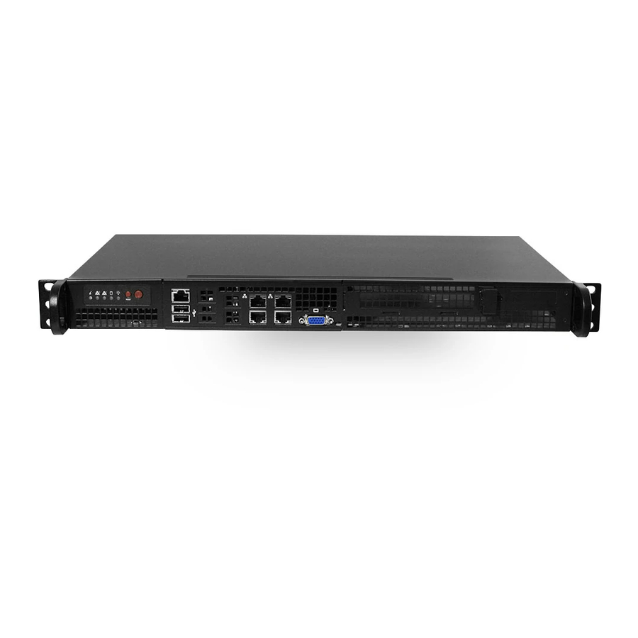
Page 12: Chassis Rear
A+ Server AS -5019D-FTN4 User's Manual Chassis Rear The illustration below shows the features included on the rear of the chassis. Power supply modules display status lights. Figure 1-4. SC505-203B Rear View Chassis Rear Features Item Features Description Power Supply... -
Page 13: Motherboard Layout
Chapter 1: Introduction 1.5 Motherboard Layout Below is a layout of the M11SDV-8C-LN4F motherboard with jumper, connector and LED locations shown. See the table on the following page for descriptions. For detailed descriptions, pinout information and jumper settings, refer to Chapter 4. IPMI_LAN LED1 LEDM1... -
Page 14: Quick Reference
Trusted Platform Module (TPM)/Port 80 Connector LAN1 - LAN4 1 GbE LAN (RJ45) Ports Header for ATX Power Signal 5VSTBY/Power ON/Power GOOD/Ground; 24pin ATX to 4pin power cable for PJ1 (Supermicro P/N: CBL-PWEX-1063) SATA0 - SATA3 SATA 3.0 Ports Unit Identifier Switch USB0-5 USB 2.0 Header... -
Page 15: Chipset Block Diagram
Chapter 1: Introduction Chipset Block Diagram MEM_DIMMA MEM_DIMMC MEM_DIMMB MEM_DIMMD 2666MHz 2666MHz SVID CPU1 SVI2 3 Phase VR PCIe3.0_x16 Slot 1 PCIe x16 ( or 2 x 8 ) 8.0GT/s Group B 0~15 PCIe3.0_x4 RJ45 x4 I350 PCIe x4 8.0GT/s Group A 12~15 PCIe3.0_x4 / SATA x 1 M.2_M PCIe x4... -
Page 16: Where To Get Replacement Components
(http://www.supermicro.com/ support/rma/). Whenever possible, repack the chassis in the original Supermicro carton, using the original packaging material. If these are no longer available, be sure to pack the chassis securely, using packaging material to surround the chassis so that it does not shift within the carton and become damaged during shipping. -
Page 17: Chapter 2 Server Installation
A+ Server AS -5019D-FTN4 User's Manual Chapter 2 Server Installation 2.1 Overview This chapter provides advice and instructions for mounting your system in a server rack. Caution: Electrostatic Discharge (ESD) can damage electronic components. To prevent such damage to PCBs (printed circuit boards), it is important to use a grounded wrist strap, handle all PCBs by their edges and keep them in anti-static bags when not in use. -
Page 18: Server Precautions
Chapter 2: Server Installation Server Precautions • Review the electrical and general safety precautions in Appendix B. • Determine the placement of each component in the rack before you install the rails. • Install the heaviest server components at the bottom of the rack first and then work your way up. -
Page 19: Reliable Ground
A+ Server AS -5019D-FTN4 User's Manual Reliable Ground A reliable ground must be maintained at all times. To ensure this, the rack itself should be grounded. Particular attention should be given to power supply connections other than the direct connections to the branch circuit (i.e. the use of power strips, etc.). -
Page 20: Installing The System Into A Rack
Chapter 2: Server Installation 2.3 Installing the System Into a Rack This section provides information on installing the AS -5019D-FTN4 system into a rack. The chassis has two rack mounting "ear" brackets, which are located on each side of the front of the chassis. -
Page 21: Installing The Server Into A Telco Rack
A+ Server AS -5019D-FTN4 User's Manual Installing the Server into a Telco Rack If you are installing the system into a two post (Telco) rack, follow the directions given on the previous pages for rack installation. The only difference in the installation procedure will be the positioning of the rack brackets to the rack. -
Page 22: Chapter 3 Maintenance And Component Installation
A+ Server AS -5019D-FTN4 User's Manual Chapter 3 Maintenance and Component Installation This chapter provides instructions on installing and replacing main system components. To prevent compatibility issues, only use components that match the specifications and/or part numbers given. Installation or replacement of most components require that power first be removed from the system. -
Page 23: Accessing The System
Chapter 3: Maintenance and Component Installation 3.2 Accessing the System The SC505 chassis features a removable top cover to allow access to components inside. Removing the Top Cover 1. Remove the five screws that hold the chassis cover in place. There are two screws on each side of the chassis, and one screw on the back. -
Page 24: Memory
A+ Server AS -5019D-FTN4 User's Manual Memory Note: Check the Supermicro website for recommended memory modules. Memory Support The M11SDV-8C-LN4F supports up to 512GB of Registered ECC DDR4 wth speeds up to 2666MHz in four DIMMs 4-channel memory bus. Populating these DIMM slots with memory modules of the same type and size will result in interleaved memory, which will improve memory performance. -
Page 25: Dimm Module Population Sequence
Chapter 3: Maintenance and Component Installation DIMM Module Population Sequence When installing memory modules, the DIMM slots should be populated in the following order: DIMMA2, then DIMMB2, DIMMA1, and then DIMMB1. • Always use DDR4 DIMM modules of the same type and speed. •... -
Page 26: Dimm Installation
A+ Server AS -5019D-FTN4 User's Manual DIMM Installation Insert the desired number of DIMMs into the memory slots based on the recommended population table on the previous page. Installing Memory Begin by removing power from the system as described in Section 3.1. -
Page 27: Motherboard Battery
Chapter 3: Maintenance and Component Installation Motherboard Battery The motherboard uses non-volatile memory to retain system information when system power is removed. This memory is powered by a lithium battery residing on the motherboard. Replacing the Battery Begin by removing power from the system as described in section 3.1. 1. -
Page 28: Chassis Components
The number of drives you choose to install may affect the number of expansion cards possible. Note: Enterprise level drives are recommended for use in Supermicro chassis and servers. For information on recommended HDDs, visit the Supermicro website product pages at https:// www.supermicro.com/products/nfo. - Page 29 Chapter 3: Maintenance and Component Installation Figure 3-3. Four 2.5" HDDs in Two Brackets, No Expansion Card Figure 3-4. One 3.5" Hard Drive and One Low Profile Expansion Card Figure 3-5. Two 2.5" Hard Drives and One Full- Height, Half-Length Expansion Card Figure 3-6.
-
Page 30: Pci Expansion Cards
A+ Server AS -5019D-FTN4 User's Manual PCI Expansion Cards The chassis includes a slot at the rear for an expansion card. The card is connected to the motherboard by means of a pre-installed riser card. Only certain storage drive configurations allow an expansion card: one 3.5"... -
Page 31: System Fans
Chapter 3: Maintenance and Component Installation System Fans The system employs two fans in the default configuration. A third can be added using an optional kit. Note: A third fan is recommended if the system includes an M.2 card or other add-on card. - Page 32 A+ Server AS -5019D-FTN4 User's Manual Single Fan Dual Fans Figure 3-8. Installing System Fans...
-
Page 33: Power Supply
Power Supply This power supply can operate at an input voltage from 100 to 240 volts. If replacing it, use the exact same model. New units can be ordered directly from Supermicro or authorized distributors. Changing the Power Supply Module: 1. -
Page 34: Chapter 4 Motherboard Connections
A+ Server AS -5019D-FTN4 User's Manual Chapter 4 Motherboard Connections This section describes the connections on the motherboard and provides pinout definitions. Note that depending on how the system is configured, not all connections are required. The LEDs on the motherboard are also described here. A motherboard layout indicating component locations may be found in Chapter 1. -
Page 35: Headers And Connectors
Chapter 4: Motherboard Connections 4.2 Headers and Connectors General Purpose I/O Header The JGP1 (General Purpose Input/Output) header is a general purpose I/O expander on a pin header via the SMBus. Refer to the table below for pin definitions. JGP1 Header Pin Definitions Pin# Definition... - Page 36 A+ Server AS -5019D-FTN4 User's Manual Speaker Header On the JD1 header, pins 4-7 are for the external speaker. Speaker Connector Pin Definitions Pin# Definition 3.3V PWR_LED_IN PWR_LED_IN SPK_IN SATA Ports Four SATA 3.0 connectors (SATA0-4), supported by the AMD EPYC™ 3000 chipset, are located on the M11SDV-8C-LN4F motherboard.
- Page 37 Chapter 4: Motherboard Connections Power SMB (I C) Header The Power System Management Bus (I C) connector (JPI C1) monitors the power supply, fan, and system temperatures. Refer to the table below for pin definitions. Power SMB Header Pin Definitions Pin# Definition Clock...
-
Page 38: Front Control Panel
JF1 contains header pins for various buttons and indicators that are normally located on a control panel at the front of the chassis. These connectors are designed specifically for use with Supermicro chassis. See the figure below for the descriptions of the front control panel buttons and LED indicators. - Page 39 Chapter 4: Motherboard Connections Power Fail LED Connect an LED cable to Power Fail connections on pins 5 and 6 of JF1 to provide warnings for a power failure. Refer to the table below for pin definitions. OH/Fan Fail Indicator Status Pin # Definition 3.3V...
- Page 40 A+ Server AS -5019D-FTN4 User's Manual HDD LED The HDD LED connection is located on pins 13 and 14 of JF1. Attach a cable to show the hard drive activity status. Refer to the table below for pin definitions. HDD LED...
-
Page 41: Ports
Note: UID can also be triggered via IPMI on the motherboard. For more information on IPMI, refer to the IPMI User's Guide posted on our website: http://www.supermicro.com. Universal Serial Bus (USB) Ports There are two (2) USB 3.0 ports (USB6/7) on the I/O back panel. -
Page 42: Jumpers
A+ Server AS -5019D-FTN4 User's Manual 4.4 Jumpers Explanation of Jumpers To modify the operation of the motherboard, jumpers are used to choose between optional settings. Jumpers create shorts between two pins to change the function associated with it. Pin 1 is identified with a square solder pad on the printed circuit board. See the motherboard layout page for jumper locations. - Page 43 Chapter 4: Motherboard Connections SMBus to PCI-E Slots Jumpers JI2C1 and JI2C2 allow you to connect the System Management Bus (I2C) to the PCI-E slots. Both jumpers must be set to the same setting (JI2C1 controls the clock and JI2C2 controls the data). The default setting is Disabled. Refer to the table below for more information.
-
Page 44: Led Indicators
A+ Server AS -5019D-FTN4 User's Manual C Bus for VRM Jumpers JVRM1 and JVRM2 allow the BMC or the PCH to access CPU and memory VRM controllers. Refer to the table below for jumper settings. Jumper Settings Jumper Setting Definition... - Page 45 Chapter 4: Motherboard Connections Power LED LED3 is an Onboard Power LED. When this LED is lit, it means power is present on the motherboard. In suspend mode, this LED will blink on and off. Be sure to turn off the system and unplug the power cord(s) before removing or installing components.
-
Page 46: Chapter 5 Software
USB/SATA DVD drive, or a USB flash drive, or the IPMI K VM console. 2. Retrieve the proper RST/RSTe driver. Go to the Supermicro web page for your motherboard and click on "Download the Latest Drivers and Utilities", select the proper driver, and copy it to a USB flash drive. - Page 47 Chapter 5: Software 4. During Windows Setup, continue to the dialog where you select the drives on which to install Windows. If the disk you want to use is not listed, click on “Load driver” link at the bottom left corner. Figure 5-2.
-
Page 48: Driver Installation
The Supermicro website contains drivers and utilities for your system at https://www. supermicro.com/wftp/driver. Some of these must be installed, such as the chipset driver. After accessing the website, go into the CDR_Images (in the parent directory of the above link) and locate the ISO file for your motherboard. Download this file to to a USB flash drive or a DVD. -
Page 49: Superdoctor ® 5
5.3 SuperDoctor ® The Supermicro SuperDoctor 5 is a program that functions in a command-line or web-based interface for Windows and Linux operating systems. The program monitors such system health information as CPU temperature, system voltages, system power consumption, fan speed, and provides alerts via email or Simple Network Management Protocol (SNMP). -
Page 50: Chapter 6 Bios
A+ Server AS -5019D-FTN4 User's Manual Chapter 6 BIOS 6.1 Introduction This chapter describes the AMI BIOS setup utility for the M11SDV-8C-LN4F and provides the instructions on navigating the setup screens. The BIOS is stored in a Flash EEPROM and can be updated. - Page 51 Note: The time is in the 24-hour format. For example, 5:30 P.M. appears as 17:30:00. The date's default value is 01/01/2016 after RTC reset. Supermicro M11SDV-8C-LN4F BIOS Version This feature displays the version of the BIOS ROM used in the system.
-
Page 52: Advanced Settings Menu
A+ Server AS -5019D-FTN4 User's Manual 6.3 Advanced Settings Menu Use the arrow keys to select the Advanced submenu and press <Enter> to access the submenu items: Warning: Take Caution when changing the Advanced settings. An incorrect value, an incorrect DRAM frequency, or an incorrect BIOS timing setting may cause the system to malfunction. - Page 53 Chapter 6: BIOS Bootup NumLock State Use this feature to set the Power-on state for the <Numlock> key. The options are On and Off. Option ROM Messages Use this feature to set the display mode for the Option ROM. Select Keep Current to display the current AddOn ROM setting.
- Page 54 A+ Server AS -5019D-FTN4 User's Manual CPU Configuration The following CPU information will display: • Type • CPU Signature • Microcode Revision • CPU Speed • L1 Data Cache • L1 Instruction Cache • L2 Cache • L3 Cache •...
- Page 55 Chapter 6: BIOS Intel (VMX) Virtualization Technology Use this feature to enable the Vanderpool Technology. This technology allows the system to run several operating systems simultaneously. The options are Disabled and Enabled. Active Processor Cores This feature determines how many CPU cores will be activated for each CPU. When All is selected, all cores in the CPU will be activated.
- Page 56 A+ Server AS -5019D-FTN4 User's Manual Monitor/Mwait Select Enabled to enable the Monitor/Mwait instructions. The Monitor instructions monitor a region of memory for writes, while MWait instructions instruct the CPU to stop until the moni- tored region begins to write. The options are Disabled and Enabled.
- Page 57 Chapter 6: BIOS System Agent (SA) Configuration The following information is displayed: • SA PCIe Code Version • VT-d Memory Configuration • Memory RC Version • Memory Frequency • Memory Timings (tCL-tRCD-tRP-tRAS) • DIMMA1 ~ DIMMB1 information Maximum Memory Frequency Use this feature to set the maximum memory frequency for onboard memory modules.
- Page 58 A+ Server AS -5019D-FTN4 User's Manual DMI/OPI Configuration The following DMI information will display: • DMI Link ASPM Control Use this feature to set the Active State Power Management (ASPM) state on the System Agent (SA) side of the DMI Link. The options are Disabled, L0s, L1, and L0sL1 DMI Extended Sync Control Use this feature to enable or disable the DMI extended synchronization.
- Page 59 Chapter 6: BIOS Max Payload Size Select Auto for the system BIOS to automatically set the maximum payload value for a PCI-E device to enhance system performance. The options are Auto, 128, and 256 TLP. Program PCIe ASPM After OPROM PCIe ASPM, the Active State Power Management for PCI-Express slots, is a power management protocol used to manage power consumption of serial-link devices installed on PCI-E slots during a prolonged off-peak time.
- Page 60 A+ Server AS -5019D-FTN4 User's Manual Peer Memory Write Enable Use this feature to enable or disable peer memory write. The options are Disabled or Enabled. M.2-H M.2-F ASPM Support This feature controls the Active State Power Management (ASPM) setting. The op- tions are Disabled, L0s, L1, L0sL1, and Auto.
- Page 61 Chapter 6: BIOS Change Settings This feature specifies the base I/O port address and the Interrupt Request address of a serial port specified by the user. Select Auto to allow the BIOS to automatically assign the base I/O and IRQ address. The options for Serial Port 1 are Auto, (IO=3F8h;...
- Page 62 A+ Server AS -5019D-FTN4 User's Manual VT-UTF8 to use UTF8 encoding to map Unicode characters into one or more bytes. The options are VT100, VT100+, VT-UTF8, and ANSI. Bits Per Second Use this feature to set the transmission speed for a serial port used in Console Redirection.
- Page 63 Chapter 6: BIOS Legacy OS Redirection Resolution Use this feature to select the number of rows and columns used in Console Redirection for legacy OS support. The options are 80x24 and 80x25. Putty KeyPad This feature selects the settings for Function Keys and KeyPad used for Putty, which is a terminal emulator designed for the Windows OS.
- Page 64 A+ Server AS -5019D-FTN4 User's Manual Parity A parity bit can be sent along with regular data bits to detect data transmission errors. Select Even if the parity bit is set to 0, and the number of 1's in data bits is even. Select Odd if the parity bit is set to 0, and the number of 1's in data bits is odd.
- Page 65 Chapter 6: BIOS Legacy Console Redirection Legacy Console Redirection Settings Legacy Redirection COM Port Use this feature to select a COM port to display redirection of Legacy OS and Legacy OPROM messages. The options are COM1 and SOL. Legacy OS Redirection Resolution Use this feature to select the number of rows and columns used in Console Redirection for legacy OS support.
- Page 66 A+ Server AS -5019D-FTN4 User's Manual EMS Bits Per Second This feature sets the transmission speed for a serial port used in Console Redirection. Make sure that the same speed is used in the host computer and the client computer. A lower transmission speed may be required for long and busy lines.
- Page 67 Chapter 6: BIOS Serial ATA Port 0 ~ Port 3 This feature displays the information detected on the installed SATA drive on the particular SATA port. • Model number of drive and capacity • Software Preserve Support Port 0 ~ Port 3 Hot Plug Set this feature to Enabled for hot plug support, which will allow the user to replace a SATA drive without shutting down the system.
- Page 68 A+ Server AS -5019D-FTN4 User's Manual High Precision Event Timer Select Enabled to activate the High Precision Event Timer (HPET) that produces periodic interrupts at a much higher frequency than a Real-time Clock (RTC) does in synchronizing multimedia streams, providing smooth playback and reducing the dependency on other timestamp calculation devices, such as an x86 RDTSC Instruction embedded in the CPU.
- Page 69 Chapter 6: BIOS PCIe/PCI/PnP Configuration Option ROM Execution PCI PERR/SERR Support Select Enabled to allow a PCI device to generate a PERR/SERR number for a PCI Bus Signal Error Event. The options are Disabled and Enabled. Above 4GB MMIO BIOS Assignment Select Enabled to decode a PCI device that supports 64-bit in the space above 4G Address.
- Page 70 A+ Server AS -5019D-FTN4 User's Manual Onboard LAN1 ~ LAN2 Option ROM Use this feature to select which firmware function to be loaded for the specified onboard LAN port at system boot. The options are Disabled, PXE, and iSCSI*. *iSCSI is only supported on Onboard LAN1. The default setting for Onboard LAN1 is PXE.
- Page 71 Chapter 6: BIOS Security Device Support If this feature and the TPM jumper on the motherboard are both set to Enable, onboard security devices will be enabled for TPM (Trusted Platform Module) support to enhance data integrity and network security. Please reboot the system for a change on this setting to take effect.
- Page 72 TPM 2.0 will restrict support for TPM 2.0 devices. Select Auto to enable support for both versions. The options are TPM 1.2, TPM 2.0, and Auto. SMCI BIOS-Based TPM Provision Support Use feature to enable the Supermicro TPM Provision support. The options are Disabled and Enabled. TXT Support Intel Trusted Execution Technology (TXT) helps protect against software-based attacks and ensures protection, confidentiality, and integrity of data stored or created on the system.
- Page 73 Chapter 6: BIOS Add an Attempt Delete Attempts Change Attempt Order TLS Authentication Configuration This submenu allows the user to configure Transport Layer Security (TLS) settings. Server CA Configuration Enroll Certification Enroll Certification Using File Use this feature to enroll certification from a file. Certification GUID Use this feature to input the certification GUID.
-
Page 74: Event Logs
A+ Server AS -5019D-FTN4 User's Manual 6.4 Event Logs Use this tab page to configure Event Log settings. Change SMBIOS Event Log Settings Enabling/Disabling Options SMBIOS Event Log Change this feature to enable or disable all features of the SMBIOS Event Logging during system boot. -
Page 75: Ipmi
Chapter 6: BIOS MECI The Multiple Event Count Increment (MECI) counter counts the number of occurences that a duplicate event must happen before the MECI counter is incremented. This is a numeric value. The default value is 1. METW The Multiple Event Time Window (METW) defines the number of minutes that must pass between duplicate log events before MECI is incremented. - Page 76 A+ Server AS -5019D-FTN4 User's Manual Configure IPV4 Support This section displays configuration features for IPV4 support. IPMI LAN Selection This feature displays the IPMI LAN setting. The default setting is Failover. IPMI Network Link Status This feature displays the IPMI Network Link status. The default setting is Shared LAN.
-
Page 77: Security Settings
Chapter 6: BIOS IPV6 Address Status This feature displays the IPV6 Address status. The default setting is Disabled. IPV6 Support Use this feature to enable IPV6 support. The options are Enabled and Disabled. *If the feature above is set to Enabled, the following settings will become available for configuration: Configuration Address Source This feature allows the user to select the source of the IP address for this computer. - Page 78 A+ Server AS -5019D-FTN4 User's Manual Password Check Select Setup for the system to check for a password at Setup. Select Always for the system to check for a password at bootup or upon entering the BIOS Setup utility. The options are Setup and Always.
- Page 79 Chapter 6: BIOS Enroll EFI Image This feature allows the image to run in Secure Boot Mode. Enroll SHA256 Hash Cer- ticate of the image into the Authorized Signature Database. Device Guard Ready Remove 'UEFI CA' from DB Use this feature to remove the Microsoft UEFI CA certificate from the database.
- Page 80 A+ Server AS -5019D-FTN4 User's Manual Forbidden Signatures Update Select Yes to load the DBX from the manufacturer's defaults. Select No to load the DBX from a file. The options are Yes and No. Append Select Yes to add the DBX from the manufacturer's defaults to the existing DBX. Select No to load the DBX from a file.
- Page 81 Chapter 6: BIOS 6.7 Boot Settings Use this tab page to configure Boot Settings. Setup Prompt Timeout Use this feature to indicate the length of time (the number of seconds) for the BIOS to wait before rebooting the system when the setup activation key is pressed. Enter the value of 65535 (0xFFFF) for the BIOS to wait indefinitely.
- Page 82 A+ Server AS -5019D-FTN4 User's Manual • Legacy/UEFI/Dual Boot Option #6 • Legacy/UEFI/Dual Boot Option #7 • Legacy/UEFI/Dual Boot Option #8 • UEFI/Dual Boot Option #9 • Dual Boot Option #10 • Dual Boot Option #11 • Dual Boot Option #12 •...
- Page 83 Chapter 6: BIOS Add New Driver Option This feature allows the user to add a new EFI driver option to the driver order for your system. Add Driver Option Use this feature to specify the name for the new driver option. Path for Boot Option Use this feature to enter the path for the new driver option in the format fsx:\path\filename.
- Page 84 A+ Server AS -5019D-FTN4 User's Manual 6.8 Save & Exit Use this tab page to configure Save & Exit settings. Save Options Discard Changes and Exit Select this feature to quit the BIOS Setup without making any permanent changes to the system configuration and reboot the computer.
- Page 85 Chapter 6: BIOS Default Options Restore Defaults To set this feature, select Restore Defaults from the Save & Exit menu and press <Enter>. These are factory settings designed for maximum system stability, but not for maximum performance. Save As User Defaults To set this feature, select Save as User Defaults from the Save &...
- Page 86 When BIOS performs the Power On Self Test, it writes checkpoint codes to I/O port 0080h. If the computer cannot complete the boot process, a diagnostic card can be attached to the computer to read I/O port 0080h (Supermicro p/n AOC-LPC80-20). For information on AMI updates, please refer to http://www.ami.com/products/.
- Page 87 Supermicro's Technical Support department for assistance. Only certified technicians should attempt to install or configure components. Read this appendix in its entirety before installing or configuring components in the Supermicro chassis. These warnings may also be found on our website at http://www.supermicro.com/about/...
- Page 88 Appendix B: Standardized Warning Statements Warnung WICHTIGE SICHERHEITSHINWEISE Dieses Warnsymbol bedeutet Gefahr. Sie befinden sich in einer Situation, die zu Verletzungen führen kann. Machen Sie sich vor der Arbeit mit Geräten mit den Gefahren elektrischer Schaltungen und den üblichen Verfahren zur Vorbeugung vor Unfällen vertraut. Suchen Sie mit der am Ende jeder Warnung angegebenen Anweisungsnummer nach der jeweiligen Übersetzung in den übersetzten Sicherheitshinweisen, die zusammen mit diesem Gerät ausgeliefert wurden.
- Page 89 A+ Server AS -5019D-FTN4 User's Manual . ٌ ا ك ً ف حالة و ٌ يك أى تتسبب ف اصابة جسذ ة ٌ هذا الزهز ع ٌ خطز !تحذ ز قبل أى تعول عىل أي هعذات،يك عىل علن بالوخاطز ال ا ٌجوة عي الذوائز...
- Page 90 Appendix B: Standardized Warning Statements Warnung Vor dem Anschließen des Systems an die Stromquelle die Installationsanweisungen lesen. ¡Advertencia! Lea las instrucciones de instalación antes de conectar el sistema a la red de alimentación. Attention Avant de brancher le système sur la source d'alimentation, consulter les directives d'installation. .יש...
- Page 91 A+ Server AS -5019D-FTN4 User's Manual Warnung Dieses Produkt ist darauf angewiesen, dass im Gebäude ein Kurzschluss- bzw. Überstromschutz installiert ist. Stellen Sie sicher, dass der Nennwert der Schutzvorrichtung nicht mehr als: 250 V, 20 A beträgt. ¡Advertencia! Este equipo utiliza el sistema de protección contra cortocircuitos (o sobrecorrientes) del edificio.
- Page 92 Appendix B: Standardized Warning Statements Power Disconnection Warning Warning! The system must be disconnected from all sources of power and the power cord removed from the power supply module(s) before accessing the chassis interior to install or remove system components. 電源切断の警告...
- Page 93 A+ Server AS -5019D-FTN4 User's Manual يجب فصم اننظاو من جميع مصادر انطاقت وإ ز انت سهك انكهرباء من وحدة امداد انطاقت قبم انىصىل إىن امنناطق انداخهيت نههيكم نتثبيج أو إ ز انت مكىناث الجهاز 경고! 시스템에 부품들을 장착하거나 제거하기 위해서는 섀시 내부에 접근하기 전에 반드시 전원...
- Page 94 Appendix B: Standardized Warning Statements Attention Il est vivement recommandé de confier l'installation, le remplacement et la maintenance de ces équipements à des personnels qualifiés et expérimentés. !אזהרה .צוות מוסמך בלבד רשאי להתקין, להחליף את הציוד או לתת שירות עבור הציוד واملدربيه...
- Page 95 A+ Server AS -5019D-FTN4 User's Manual Warnung Diese Einheit ist zur Installation in Bereichen mit beschränktem Zutritt vorgesehen. Der Zutritt zu derartigen Bereichen ist nur mit einem Spezialwerkzeug, Schloss und Schlüssel oder einer sonstigen Sicherheitsvorkehrung möglich. ¡Advertencia! Esta unidad ha sido diseñada para instalación en áreas de acceso restringido. Sólo puede obtenerse acceso a una de estas áreas mediante la utilización de una herramienta especial,...
- Page 96 Appendix B: Standardized Warning Statements Battery Handling Warning! There is the danger of explosion if the battery is replaced incorrectly. Replace the battery only with the same or equivalent type recommended by the manufacturer. Dispose of used batteries according to the manufacturer's instructions 電池の取り扱い...
- Page 97 A+ Server AS -5019D-FTN4 User's Manual هناك خطر من انفجار يف حالة اسحبذال البطارية بطريقة غري صحيحة فعليل اسحبذال البطارية فقط بنفس النىع أو ما يعادلها مام أوصث به الرشمة املصنعة جخلص من البطاريات املسحعملة وفقا لحعليامت الرشمة الصانعة 경고! 배터리가...
- Page 98 Appendix B: Standardized Warning Statements ¡Advertencia! Puede que esta unidad tenga más de una conexión para fuentes de alimentación. Para cortar por completo el suministro de energía, deben desconectarse todas las conexiones. Attention Cette unité peut avoir plus d'une connexion d'alimentation. Pour supprimer toute tension et tout courant électrique de l'unité, toutes les connexions d'alimentation doivent être débranchées.
- Page 99 A+ Server AS -5019D-FTN4 User's Manual Backplane Voltage Warning! Hazardous voltage or energy is present on the backplane when the system is operating. Use caution when servicing. バックプレーンの電圧 システムの稼働中は危険な電圧または電力が、 バックプレーン上にかかっています。 修理する際には注意く ださい。 警告 当系统正在进行时,背板上有很危险的电压或能量,进行维修时务必小心。 警告 當系統正在進行時,背板上有危險的電壓或能量,進行維修時務必小心。 Warnung Wenn das System in Betrieb ist, treten auf der Rückwandplatine gefährliche Spannungen oder Energien auf.
- Page 100 Appendix B: Standardized Warning Statements هناك خطز مه التيار الكهزبايئ أوالطاقة املىجىدة عىل اللىحة عندما يكىن النظام يعمل كه حذ ر ا عند خدمة هذا الجهاس 경고! 시스템이 동작 중일 때 후면판 (Backplane)에는 위험한 전압이나 에너지가 발생 합니다. 서비스 작업 시 주의하십시오. Waarschuwing Een gevaarlijke spanning of energie is aanwezig op de backplane wanneer het systeem in gebruik is.
- Page 101 A+ Server AS -5019D-FTN4 User's Manual תיאום חוקי החשמל הארצי !אזהרה .התקנת הציוד חייבת להיות תואמת לחוקי החשמל המקומיים והארציים تركيب املعدات الكهربائية يجب أن ميتثل للقىاويه املحلية والىطىية املتعلقة بالكهرباء 경고! 현 지역 및 국가의 전기 규정에 따라 장비를 설치해야 합니다.
- Page 102 Appendix B: Standardized Warning Statements Attention La mise au rebut ou le recyclage de ce produit sont généralement soumis à des lois et/ou directives de respect de l'environnement. Renseignez-vous auprès de l'organisme compétent. סילוק המוצר !אזהרה .סילוק סופי של מוצר זה חייב להיות בהתאם להנחיות וחוקי המדינה التخلص...
- Page 103 A+ Server AS -5019D-FTN4 User's Manual Warnung Gefährlich Bewegende Teile. Von den bewegenden Lüfterblätter fern halten. Die Lüfter drehen sich u. U. noch, wenn die Lüfterbaugruppe aus dem Chassis genommen wird. Halten Sie Finger, Schraubendreher und andere Gegenstände von den Öffnungen des Lüftergehäuses entfernt.
- Page 104 Verbindungskabeln, Stromkabeln und/oder Adapater, die Ihre örtlichen Sicherheitsstandards einhalten. Der Gebrauch von anderen Kabeln und Adapter können Fehlfunktionen oder Feuer verursachen. Die Richtlinien untersagen das Nutzen von UL oder CAS zertifizierten Kabeln (mit UL/CSA gekennzeichnet), an Geräten oder Produkten die nicht mit Supermicro gekennzeichnet sind.
- Page 105 .قيرح وأ لطع يف ببستي دق ىرخأ تالوحمو تالباك يأ مادختسا .ميلسلا سباقلاو لصوملا مجح لبق نم ةدمتعملا تالباكلا مادختسا تادعملاو ةيئابرهكلا ةزهجألل ةمالسلا نوناق رظحيUL وأCSA ( ةمالع لمحت يتلاوUL/CSA) لبق نم ةددحملاو ةينعملا تاجتنملا ريغ ىرخأ تادعم يأ عمSupermicro.
- Page 106 사항을 준수하여 제공되거나 지정된 연결 혹은 구매 케이블, 전원 케이블 및 AC 어댑터를 사용하십시오. 다른 케이블이나 어댑터를 사용하면 오작동이나 화재가 발생할 수 있습니다. 전기 용품 안전법은 UL 또는 CSA 인증 케이블 (코드에 UL / CSA가 표시된 케이블)을 Supermicro 가 지정한 제품 이외의 전기 장치에 사용하는 것을 금지합니다. Stroomkabel en AC-Adapter...
- Page 107 Appendix C: System Specifications Appendix C System Specifications Processors Supports an AMD EPYC 3251 SoC processor Chipset System on Chip BIOS 128 Mb AMI BIOS SPI Flash BIOS UEFI 2.6, ACPI 6.1, PCI FAV 3.0, SMBIOS 3.1, SPI dual/quad speed support, Real Time Clock (RTC) wakeup Memory Up to 512GB of Registered ECC DDR4 with speeds of up to 2666MHz in four DIMMs 4-channel memory bus.
- Page 108 A+ Server AS -5019D-FTN4 User's Manual Electromagnetic Emissions: FCC Class A, EN 55032 Class A, EN 61000-3-2/3-3, CISPR 32 Class A Electromagnetic Immunity: EN 55024/CISPR 24, (EN 61000-4-2, EN 61000-4-3, EN 61000-4-4, EN 61000-4-5, EN 61000-4-6, EN 61000-4-8, EN 61000-4-11)
- Page 109 Warning: Do not upgrade the BIOS unless your system has a BIOS-related issue. Flashing the wrong BIOS can cause irreparable damage to the system. In no event shall Supermicro be liable for direct, indirect, special, incidental, or consequential damages arising from a BIOS update.
- Page 110 A+ Server AS -5019D-FTN4 User Manual The file system supported by the recovery block is FAT (including FAT12, FAT16, and FAT32) which is installed on a bootable or non-bootable USB-attached device. However, the BIOS might need several minutes to locate the SUPER.ROM file if the media size becomes too large due to the huge volumes of folders and files stored in the device.
- Page 111 Appendix D: UEFI BIOS Recovery 3. After locating the healthy BIOS binary image, the system will enter the BIOS Recovery menu as shown below. Note: At this point, you may decide if you want to start the BIOS recovery. If you decide to proceed with BIOS recovery, follow the procedures below.
- Page 112 A+ Server AS -5019D-FTN4 User Manual 5. After the BIOS recovery process is complete, press any key to reboot the system. 6. Using a different system, extract the BIOS package into a USB flash drive. 7. Press <Del> continuously during system boot to enter the BIOS Setup utility. From the top of the tool bar, select Boot to enter the submenu.
- Page 113 Appendix D: UEFI BIOS Recovery 8. When the UEFI Shell prompt appears, type fs# to change the device directory path. Go to the directory that contains the BIOS package you extracted earlier from Step 6. Enter flash.nsh BIOSname.### at the prompt to start the BIOS update process. Note: Do not interrupt this process until the BIOS flashing is complete.
Need help?
Do you have a question about the AS -5019D-FTN4 and is the answer not in the manual?
Questions and answers