Table of Contents
Advertisement
Quick Links
Advertisement
Table of Contents

Related Manuals for Supermicro SuperServer 5019A-FN5T


Summary of Contents for Supermicro SuperServer 5019A-FN5T
- Page 1 SuperServer ® 5019A-FN5T USER’S MANUAL Revision 1.0...
- Page 2 State of California, USA. The State of California, County of Santa Clara shall be the exclusive venue for the resolution of any such disputes. Supermicro's total liability for all claims will not exceed the price paid for the hardware product.
- Page 3 If you have any questions, please contact our support team at: support@supermicro.com This manual may be periodically updated without notice. Please check the Supermicro website for possible updates to the manual revision level. Secure Data Deletion A secure data deletion tool designed to fully erase all data from storage devices can be found on our website: https://www.supermicro.com/about/policies/disclaimer.cfm?url=/wftp/utility/...
-
Page 4: Table Of Contents
SuperServer 5019A-FN5T User's Manual Contents Chapter 1 Introduction 1.1 Overview ..........................8 1.2 System Features ........................9 1.3 Chassis Features .......................10 Control Panel ........................10 Front Features ........................11 Rear Features ........................12 1.4 Motherboard Layout ......................13 Quick Reference Table ......................14 1.5 Server Installation and Setup .....................17 Unpacking the System ......................17... - Page 5 Preface Memory Support ......................25 ESD Precautions ......................25 DIMM Module Population Configuration ................26 DIMM Module Population Sequence ................27 DIMM Installation ......................28 DIMM Removal ......................28 M.2 Card Installation ......................29 Motherboard Battery ......................31 3.4 Chassis Components ......................32 PCI Expansion Cards .......................32 Storage Drives ........................34 Installing Fixed Internal Drives ..................34 System Fans ........................35 Checking the Server Air Flow ..................37...
- Page 6 SuperServer 5019A-FN5T User's Manual BMC ADMIN User Password ....................59 Chapter 6 BIOS 6.1 Introduction .........................60 Starting the Setup Utility ....................60 6.2 Main Setup .........................61 6.3 Advanced ..........................63 6.4 Event Logs .........................85 6.5 IPMI ............................87 6.6 Security ..........................90 6.7 Boot ............................94 6.8 Save &...
- Page 7 Super Micro Computer, Inc. 980 Rock Ave. San Jose, CA 95131 U.S.A. Tel: +1 (408) 503-8000 Fax: +1 (408) 503-8008 Email: marketing@supermicro.com (General Information) support@supermicro.com (Technical Support) Website: www.supermicro.com Europe Address: Super Micro Computer B.V. Het Sterrenbeeld 28, 5215 ML...
-
Page 8: Overview
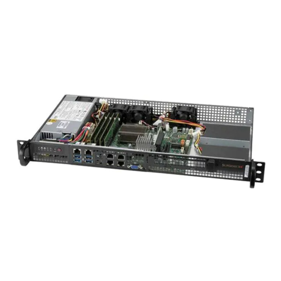
SuperServer 5019A-FN5T User's Manual Chapter 1 Introduction 1.1 Overview This chapter provides a brief outline of the functions and features of the SuperServer 5019A-FN5T. This server is based on the A2SDV-16C-TLN5F motherboard and the CSE-505-203B chassis. In addition to the motherboard and chassis, several important parts that are included with the system are listed below. -
Page 9: System Features
Chapter 1: Introduction 1.2 System Features The table below is an overview of the main features of the SuperServer 5019A-FN5T. System Features Processor Intel® Atom Processor C3958 in a FCBGA1310 type socket Motherboards A2SDV-16C-TLN5F Chassis CSE-505-203B Memory Supports up to 256GB Registered ECC RDIMM and DDR4-2400MHz or up to 64GB Unbuffered ECC/non-ECC... -
Page 10: Chassis Features
SuperServer 5019A-FN5T User's Manual 1.3 Chassis Features Control Panel The switches and LEDs located on the control panel are described below. See Chapter 4 for details on the control panel connections. The main power switch is used to apply or remove power from the power supply to the server. -
Page 11: Front Features
Chapter 1: Introduction Front Features The CSE-505-203B is a 1U short-depth chassis. See the illustration below for the features included on the front of the chassis. Figure 1-2. Server Front View Server Front Features Item Feature Description Bracket Ear Secures the chassis into the rack Control Panel Front control panel with LEDs and buttons (see the previous page) I/O Ports... -
Page 12: Rear Features
SuperServer 5019A-FN5T User's Manual Rear Features The illustrations below show the features included on the rear of the chassis. Figure 1-3. Server Rear View Server Rear Features Item Feature Description Internal fans Power Supply 200W AC Gold power supply... -
Page 13: Motherboard Layout
Chapter 1: Introduction 1.4 Motherboard Layout Below is a layout of the A2SDV-16C-TLN5F motherboard with jumper, connector, and LED locations shown. See the table on the following page for descriptions. For detailed descriptions, pinout information, and jumper settings, refer to Chapter 4. LAN1 JNCSI1 IPMI... -
Page 14: Quick Reference Table
SuperServer 5019A-FN5T User's Manual Quick Reference Table Jumper Description Default Setting JBR1 BIOS Recovery Pins 1-2 (Normal) JBT1 CMOS Clear Open (Normal) C1/JI SMB to PCIe Slots Enable/Disable Pins 1-2 (Enabled) JNCSI1 IPMI Shared LAN Port Selection ON (short): LAN1, OFF (open): LAN2... - Page 15 Chapter 1: Introduction Connector Description JSD1 SATA Disk On Module (DOM) Power Connector JSMB1 External BMC I C Header JTGLED1 LAN4 - LAN5 Activity LED Header JTPM1 Trusted Platform Module (TPM)/Port 80 Connector JUIDB1 Unit ID Button LAN1 - LAN5 LAN1: Gigabit Ethernet (RJ45) Port LAN2 - LAN5: 10Gigabit Ethernet (RJ45) Ports SLOT6, SLOT7...
- Page 16 SuperServer 5019A-FN5T User's Manual Figure 1-5. Chipset System Block Diagram Note: This is a general block diagram and may not exactly represent the features on your motherboard. See the System Specifications appendix for the actual specifications of your motherboard.
-
Page 17: Server Installation And Setup
Chapter 1: Introduction 1.5 Server Installation and Setup The server is shipped with the processor and the motherboard installed in the chassis. Several steps are necessary to begin using your server. You must add memory, install the hard drives, and mount the system in place. Unpacking the System Inspect the box in which the system was shipped and note if it was damaged. -
Page 18: Chapter 2 Server Installation
SuperServer 5019A-FN5T User's Manual Chapter 2 Server Installation 2.1 Overview This chapter provides advice and instructions for mounting your system in a server rack. If your system is not already fully integrated with system memory etc., refer to Chapter 3 for details on installing those specific components. -
Page 19: Server Precautions
Chapter 2: Server Installation • Always make sure the rack is stable before extending a server or other component from the rack. • You should extend only one server or component at a time - extending two or more simul- taneously may cause the rack to become unstable. -
Page 20: Circuit Overloading
SuperServer 5019A-FN5T User's Manual Circuit Overloading Consideration should be given to the connection of the equipment to the power supply circuitry and the effect that any possible overloading of circuits might have on overcurrent protection and power supply wiring. Appropriate consideration of equipment nameplate ratings should be used when addressing this concern. -
Page 21: Installing The Chassis Into The Rack
Chapter 2: Server Installation 2.3 Installing the Chassis into the Rack This section provides information on installing the CSE-505-203B chassis into a rack unit. Due to the variety of rack units on the market, the assembly procedure might differ slightly. Also refer to the installation instructions that came with the rack unit you are using. -
Page 22: Installing To A Telco Rack
SuperServer 5019A-FN5T User's Manual Installing to a Telco Rack The 5019A-FN5T supports Telco Rack installation. The compact design allows it to be installed into a Telco rack without the use of rails. Figure 2-2. Installing the Server into a Rack Note: Figures are for illustrative purposes only. -
Page 23: Chapter 3 Maintenance And Component Installation
Chapter 3: Maintenance and Component Installation Chapter 3 Maintenance and Component Installation This chapter provides instructions on installing and replacing main system components. To prevent compatibility issues, only use components that match the specifications and/or part numbers given. Installation or replacement of most components require that power first be removed from the system. -
Page 24: Accessing The System
SuperServer 5019A-FN5T User's Manual 3.2 Accessing the System Removing the Chassis Cover 1. Power down the system as described in Section 3.1. 2. Remove one screw from the chassis rear and two screws from each chassis side. 3. Lift the cover up and off the chassis. -
Page 25: Motherboard Components
Use a grounded wrist strap designed to prevent static discharge. • Handle the memory module by its edges only. • Put the memory modules into the antistatic bags when not in use. • Check the Supermicro website for recommended memory modules. -
Page 26: Dimm Module Population Configuration
SuperServer 5019A-FN5T User's Manual DIMM Module Population Configuration For optimal memory performance, follow the table below when populating memory. Memory Population (Balanced) Total System DIMMA1 DIMMB1 DIMMA2 DIMMB2 Memory 16GB 16GB 32GB 16GB 16GB 32GB 16GB 16GB 16GB 16GB 64GB... -
Page 27: Dimm Module Population Sequence
Chapter 3: Maintenance and Component Installation DIMM Module Population Sequence When installing memory modules, the DIMM slots should be populated in the following order: DIMMA1, DIMMB1, DIMMA2, DIMMB2. • Always use DDR4 DIMM modules of the same type, size and speed. •... -
Page 28: Dimm Installation
SuperServer 5019A-FN5T User's Manual DIMM Installation Caution: Exercise extreme caution when installing or removing memory modules to prevent any possible damage to the DIMMs or slots. Begin by removing power from the system as described in Section 3.1. 1. Decide on the number of DIMMs to install and follow the DIMM population sequence table shown previously. -
Page 29: Card Installation
Chapter 3: Maintenance and Component Installation M.2 Card Installation The A2SDV-16C-TLN5F supports two M.2 connectors: one M.2 M-Key 2242/2280 PCIe 3.0 x2 SATA connector and one B-Key 3042/2280 PCIe 3.0 x2 SATA/USB3 connector. To install an M.2 card, first locate the connector and the standoff on the motherboard. 1. - Page 30 SuperServer 5019A-FN5T User's Manual JPL1 SRW1 M-Key JPG1 Standoff BMC AST2400 LEDBMC COM1 LAN1(IPMI_LAN) USB2/3(3.0) USB0/1(3.0) LAN4/ LAN2/ LAN5 LAN3 JSMB1 JPTG1 COM2 SRW2 M-Key JNCSI1 JBT1 Standoff JIPMB1 JMD2 M-Key KEY-M PCIE3/SATA3 Connector JSEL1 JSD1 SATA DOM POWER A2SDV-16C-TLN5F REV:1.1...
-
Page 31: Motherboard Battery
Chapter 3: Maintenance and Component Installation Motherboard Battery Caution: There is a danger of explosion if the onboard battery is installed in the wrong orientation with reversed polarities. This battery must be replaced only with the same or an equivalent type recommended by the manufacturer (CR2032). Dispose of used batteries according to the manufacturer's instructions. -
Page 32: Chassis Components
SuperServer 5019A-FN5T User's Manual 3.4 Chassis Components This section provides instructions on installing and replacing system components. To assure compatibility, only use components that match the specifications or part numbers given. PCI Expansion Cards The system supports an optional riser card to allow a full-height, half-length expansion card to fit inside the chassis. - Page 33 Chapter 3: Maintenance and Component Installation Installing the Expansion Card Assembly 1. Insert the expansion card into the riser card. 2. Insert the riser card and PCI card assembly into the motherboard. 3. Secure the PCI slot bracket to the chassis with the clip. Riser Card Riser Card Bracket...
-
Page 34: Storage Drives
SuperServer 5019A-FN5T User's Manual Storage Drives The system supports two internal 2.5" SSD drives. Note: Enterprise level drives are recommended for use in Supermicro servers. For information on recommended HDDs, visit the Supermicro website product pages at https://www. supermicro.com/products/nfo. Installing Fixed Internal Drives Installing 2.5"... -
Page 35: System Fans
Chapter 3: Maintenance and Component Installation System Fans The SuperServer 5019A-FN5T comes with three fans. The fans can adjust their speed according to the heat level sensed in the system, which results in more efficient and quieter fan operation. Fan speed is controlled by IPMI. Each fan has its own separate tachometer. - Page 36 SuperServer 5019A-FN5T User's Manual 6. Install a new fan into the drive tray. 7. Connect the fan to the motherboard. 8. Reinstall the chassis cover. 9. Reconnect the power cord and power up the system. 10. Check that the overheat/fan fail LED on the control panel is off.
-
Page 37: Checking The Server Air Flow
Chapter 3: Maintenance and Component Installation Checking the Server Air Flow • Make sure there are no objects to obstruct airflow in and out of the server. • Use only recommended server parts. • Make sure no wires or foreign objects obstruct air flow through the chassis. Pull all excess cabling out of the airflow path or use shorter cables. -
Page 38: Power Supply
The 5019A-FN5T supports one 200 W AC Gold power supply. The power supply is auto- switching capable. The 200 W AC power supply can operate at a 100V to 240V input range. New units can be ordered directly from Supermicro or authorized distributors. Replacing Power Supply 1. -
Page 39: Connecting Cables
Chapter 3: Maintenance and Component Installation Connecting Cables The 5019A-FN5T system comes with cables to connect chassis components such as SATA cables, fans, and expansion cards to the motherboard and the power supply. The cables are pre-installed in the system and are routed to optimize cooling in the chassis. If disconnecting a cable, reconnect it in the same configuration. -
Page 40: Chapter 4 Motherboard Connections
SuperServer 5019A-FN5T User's Manual Chapter 4 Motherboard Connections This section describes the connections on the motherboard and provides pinout definitions. Note that depending on how the system is configured, not all connections are required. Please review the Safety Precautions in Appendix B before installing or removing components. -
Page 41: Headers And Connectors
Chapter 4: Motherboard Connections HDD Power Connector JPH1 is a 4-pin power connector for HDD use. It provides power from the motherboard to the onboard HDD. 4-pin HDD Power Pin Definitions Pin# Definition 4.2 Headers and Connectors Fan Headers The A2SDV-16C-TLN5F has six 4-pin fan headers (FAN1 ~ FAN4, FANA, FANB). These headers are backwards-compatible with the traditional 3-pin fans. - Page 42 JPW1 SuperServer 5019A-FN5T User's Manual General Purpose I/O Header JGP1 is a 10-pin general purpose I/O header. Each pin can be configured to be an input or output pin. The GPIO is controlled via the PCA9554 8-bit GPIO expansion. The base address is 0xF040(D31:F4).
- Page 43 The JTPM1 header is used to connect a Trusted Platform Module (TPM)/Port 80, which is available from Supermicro. A TPM/Port 80 connector is a security device that supports encryption and authentication in hard drives. It allows the motherboard to deny access if the TPM associated with the storage drive is not installed in the system.
- Page 44 SuperServer 5019A-FN5T User's Manual External BMC I C Header A System Management Bus header for additional slave devices or sensors is located at JSMB1. See the table below for pin definitions. External I C Header Pin Definitions Pin# Definition Data...
-
Page 45: Front Control Panel
JF1 contains header pins for various buttons and indicators that are normally located on a control panel at the front of the chassis. These connectors are designed specifically for use with Supermicro chassis. See the figure below for the descriptions of the front control panel buttons and LED indicators. - Page 46 SuperServer 5019A-FN5T User's Manual Reset Button The Reset Button connection is located on pins 3 and 4 of JF1. Attach it to a hardware reset switch on the computer case. Refer the table below for pin definitions. Reset Button Pin Definitions (JF1)
- Page 47 Chapter 4: Motherboard Connections HDD LED The HDD LED connection is located on pins 13 and 14 of JF1. Attach a cable to to show hard drive activity status. Refer to the table below for pin definitions. HDD LED Pin Definitions (JF1) Pin# Definition 3.3V Stdby...
-
Page 48: Ports
SuperServer 5019A-FN5T User's Manual 4.4 Ports Front I/O Ports See Figure 4-1 below for the locations and descriptions of the various I/O ports on the front of the motherboard. Figure 4-1. Rear I/O Port Locations and Definitions Rear I/O Ports... - Page 49 UID Indicator provides easy identification of a system unit that may be in need of service. Note: UID can also be triggered via IPMI on the motherboard. For more information on IPMI, please refer to the IPMI User's Guide posted on our website at https://www.supermicro.com/ support/manuals/. UID Switch...
-
Page 50: Jumpers
SuperServer 5019A-FN5T User's Manual 4.5 Jumpers Explanation of Jumpers To modify the operation of the motherboard, jumpers are used to choose between optional settings. Jumpers create shorts between two pins to change the function associated with it. Pin 1 is identified with a square solder pad on the printed circuit board. See the motherboard layout page for jumper locations. - Page 51 Chapter 4: Motherboard Connections LAN1 Port Enable/Disable Use jumper JPL1 to enable or disable LAN1. Refer to the table below for jumper settings. LAN Enable/Disable Jumper Settings Jumper Setting Definition Pins 1-2 Enabled (Deafult) Pins 2-3 Disabled Manufacturing Mode Select Close pins 2-3 of jumper JPME2 to bypass SPI flash security and force the system to operate in the manufacturing mode, which will allow the user to flash the system firmware from a host server for system setting modifications.
- Page 52 SuperServer 5019A-FN5T User's Manual 10Gb LAN Enable/Disable Use jumper JPTG1 to enable or disable 10G LAN2/3/4/5. Refer to the table below for jumper settings. 10Gb LAN Enable/Disable Jumper Settings Jumper Setting Definition Pins 1-2 Enabled (Default) Pins 2-3 Disabled SMBus to PCI Slots...
- Page 53 Chapter 4: Motherboard Connections Watch Dog JWD1 controls the Watch Dog function. Watch Dog is a monitor that can reboot the system when a software application hangs. Jumping pins 1-2 will cause Watch Dog to reset the system if an application hangs. Jumping pins 2-3 will generate a non-maskable interrupt signal for the application that hangs.
-
Page 54: Led Indicators
SuperServer 5019A-FN5T User's Manual 4.6 LED Indicators LAN LEDs Five LAN ports (LAN1 - LAN5) are located on the I/O back panel. Each Ethernet LAN port has two LEDs. One LED indicates activity, while the other Link LED may be green, amber, or off to indicate the speed of the connection. -
Page 55: Chapter 5 Software
USB/SATA DVD drive, or a USB flash drive, or the IPMI KVM console. 2. Go to the Supermicro web page for your motherboard and click on "Download the Latest Drivers and Utilities", select the proper driver, and copy it to a USB flash drive. - Page 56 SuperServer 5019A-FN5T User's Manual 4. During Windows Setup, continue to the dialog where you select the drives on which to install Windows. If the disk you want to use is not listed, click on “Load driver” link at the bottom left corner.
-
Page 57: Driver Installation
The Supermicro website contains drivers and utilities for your system at https://www. supermicro.com/wftp/driver. Some of these must be installed, such as the chipset driver. After accessing the website, go into the CDR_Images (in the parent directory of the above link) and locate the ISO file for your motherboard. Download this file to a USB flash drive or a DVD. -
Page 58: Superdoctor ® 5
5.3 SuperDoctor ® The Supermicro SuperDoctor 5 is a program that functions in a command-line or web-based interface for Windows and Linux operating systems. The program monitors such system health information as CPU temperature, system voltages, system power consumption, fan speed, and provides alerts via email or Simple Network Management Protocol (SNMP). -
Page 59: Ipmi
There are several BIOS settings that are related to IPMI. For general documentation and information on IPMI, please visit our website at: http://www.supermicro.com/products/nfo/IPMI.cfm. BMC ADMIN User Password For security, each system is assigned a unique default BMC password for the ADMIN user. -
Page 60: Chapter 6 Bios
SuperServer 5019A-FN5T User's Manual Chapter 6 BIOS 6.1 Introduction This chapter describes the AMIBIOS™ Setup utility for the A2SDV-TLN5F series motherboard. The BIOS is stored on a chip and can be easily upgraded using a flash program. Note: Due to periodic changes to the BIOS, some settings may have been added or deleted and might not yet be recorded in this manual. -
Page 61: Main Setup
Note: The time is in the 24-hour format. For example, 5:30 P.M. appears as 17:30:00. The date's default value is the BIOS build date after RTC reset. Supermicro A2SDV-16C-TLN5F BIOS Version This item displays the version of the BIOS ROM used in the system. - Page 62 SuperServer 5019A-FN5T User's Manual Memory Information Total Memory This item displays the total size of memory available in the system. Memory Speed This item displays the default speed of the memory modules installed in the system.
-
Page 63: Advanced
Chapter 6: BIOS 6.3 Advanced Use this menu to configure Advanced settings. Warning: Take caution when changing the Advanced settings. An incorrect value, a very high DRAM frequency or an incorrect BIOS timing setting may cause the system to malfunction. When this occurs, restore to default manufacturer settings. - Page 64 SuperServer 5019A-FN5T User's Manual Power Configuration Watch Dog Function If enabled, the Watch Dog timer will allow the system to reboot when it is inactive for more than 5 minutes. The options are Disabled and Enabled. Power Button Function This feature controls how the system shuts down when the power button is pressed. Select 4 Seconds Override for the user to power off the system after pressing and holding the power button for 4 seconds or longer.
- Page 65 Chapter 6: BIOS Select Enable to activate TM1 support for system thermal monitoring. TM1 allows the CPU to regulate its power consumption based upon the modulation of the CPU Internal clock when the CPU temperature reaches a pre-defined overheating threshold. The options are Disable and Enable.
- Page 66 SuperServer 5019A-FN5T User's Manual L1 Prefetcher If enabled, the hardware prefetcher will prefetch streams of data and instructions from the main memory to the L1 cache to improve CPU performance. The options are Enable and Disable. L2 Prefetcher If enabled, the hardware prefetcher will prefetch streams of data and instructions from the main memory to the L2 cache to improve CPU performance.
- Page 67 Chapter 6: BIOS AES-NI Select Enable to use the Intel Advanced Encryption Standard (AES) New Instructions (NI) to ensure data security. The options are Disable and Enable. Lock PACKAGE_RAPL_LIMIT Use this feature to lock the MSR 0x610 bit. The options are Disable and Enable. *If the feature above is set to Disable, the next three features will be available for configuration: PL1 Time Window...
- Page 68 SuperServer 5019A-FN5T User's Manual VT-d Select Enabled to enable Intel Virtualization Technology support for Direct I/O VT-d by reporting the I/O device assignments to VMM through the DMAR ACPI Tables. This feature offers fully-protected I/O resource-sharing across the Intel platforms, providing the user with greater reliability, security and availability in networking and data-sharing.
- Page 69 Chapter 6: BIOS Patrol Scrub Period Use this feature to select the Patrol Scrub period. The options are 24 hours, 10 hours, 4 hours, and 1 hour. Demand Scrub Enable Demand Scrubbing is a process that allows the CPU to correct correctable memory errors found in a memory module.
- Page 70 SuperServer 5019A-FN5T User's Manual South Bridge Configuration South Bridge Configuration • USB Module Version • USB Controllers • USB Devices Legacy USB Support Select Enabled to support onboard legacy USB devices. Select Auto to disable legacy support if there are no legacy USB devices present. Select Disable to have all USB devices available for EFI applications only.
- Page 71 Chapter 6: BIOS SATA Configuration SATA1 SATA 1 Enable controller This item enables or disables the onboard SATA controller supported by the processor. The options are Enabled and Disabled. SATA 1 LPM (Link Power Management) When this item is set to Enabled, the SATA AHCI controller manages the power usage of the SATA link.
- Page 72 SuperServer 5019A-FN5T User's Manual I-SATA (M.2 - B Key) ~ I-SATA (M.2 M Key) This following information is displayed for each M.2 drive entry: • Device Information • Device Size Enable/disable port Use this feature to disable or enable the SATA port number. The options are Enabled and Disabled.
- Page 73 Chapter 6: BIOS PCIe/PCI/PnP Configuration The following PCI information will be displayed: • PCI Bus Driver Version • PCI Devices Common Settings: Above 4G Decoding (Available if the system supports 64-bit PCI decoding) Select Enabled to decode a PCI device that supports 64-bit in the space above 4G Address. The options are Disabled and Enabled.
- Page 74 SuperServer 5019A-FN5T User's Manual KEY-B SATA3/USB3 OPROM Use this item to select the firmware type for the add-on card for this slot. The options are Disabled, Legacy, and EFI. KEY-M PCIE3/SATA3 OPROM Use this item to select the firmware type for the add-on card for this slot. The options are Disabled, Legacy, and EFI.
- Page 75 Chapter 6: BIOS Super IO Configuration Super IO Chip AST2400 Serial Port 1 Configuration COM1 Serial Port 1 Select Enabled to enable the onboard serial port specified by the user. The options are Disabled and Enabled. Device Settings This feature displays the base I/O port address and the Interrupt Request address of a serial port specified by the user.
- Page 76 SuperServer 5019A-FN5T User's Manual Serial Port 2 Attribute Use this feature to select the mode for serial port 2. The options are SOL and COM. Serial Port Console Redirection COM 1 Console Redirection Select Enabled to enable COM Port 1 for Console Redirection, which will allow a client machine to be connected to a host machine at a remote site for networking.
- Page 77 Chapter 6: BIOS COM1 Stop Bits A stop bit indicates the end of a serial data packet. Select 1 Stop Bit for standard serial data communication. Select 2 Stop Bits if slower devices are used. The options are 1 and 2. COM1 Flow Control Use this item to set the flow control for Console Redirection to prevent data loss caused by buffer overflow.
- Page 78 SuperServer 5019A-FN5T User's Manual SOL/COM2 Terminal Type Use this feature to select the target terminal emulation type for Console Redirection. Select VT100 to use the ASCII Character set. Select VT100+ to add color and function key support. Select ANSI to use the Extended ASCII Character Set. Select VT-UTF8 to use UTF8 encoding to map Unicode characters into one or more bytes.
- Page 79 Chapter 6: BIOS SOL/COM2 Resolution 100x31 Select Enabled for extended-terminal resolution support. The options are Disabled and Enabled. SOL/COM2 Putty KeyPad This feature selects Function Keys and KeyPad settings for Putty, which is a terminal emulator designed for the Windows OS. The options are VT100, LINUX, XTERMR6, SCO, ESCN, and VT400.
- Page 80 SuperServer 5019A-FN5T User's Manual Flow Control Use this feature to set the flow control for Console Redirection to prevent data loss caused by buffer overflow. Send a "Stop" signal to stop sending data when the receiving buffer is full. Send a "Start" signal to start sending data when the receiving buffer is empty. The options are None, Hardware RTS/CTS, and Software Xon/Xoff.
- Page 81 Chapter 6: BIOS Pending operation Use this item to schedule a TPM-related operation to be performed by a security device for system data integrity. Your system will reboot to carry out a pending TPM operation. The options are None and TPM Clear. Note: Your system will reboot to carry out a pending TPM operation.
- Page 82 SuperServer 5019A-FN5T User's Manual SHA256 PCR Bank Use this item to disable or enable the SHA256 Platform Configuration Register (PCR) bank for the installed TPM device. The options are Disabled and Enabled. Pending operation Use this item to schedule a TPM-related operation to be performed by a security device for system data integrity.
- Page 83 Chapter 6: BIOS iSCSI Configuration iSCSI Initiator Name This feature allows the user to enter the unique name of the iSCSI Initiator in IQN format. Once the name of the iSCSI Initiator is entered into the system, configure the proper settings for the following items.
- Page 84 SuperServer 5019A-FN5T User's Manual Device Name This item displays the adapter device name. Chip Type This item displays the network adapter chipset name. PCI Device ID This item displays the device ID number. PCI Address This item displays the PCI address for this computer. PCI addresses are three two-digit hexadecimal numbers.
-
Page 85: Event Logs
Chapter 6: BIOS 6.4 Event Logs Use this menu to configure Event Log settings. Change SMBIOS Event Log Settings Enabling/Disabling Options PCIe ELog Support Use this feature to enable or disable PCIe error logging suport. The options are Disabled and Enabled. Memory ELog Support Use this feature to enable or disable memory error logging suport. - Page 86 SuperServer 5019A-FN5T User's Manual Erasing Settings Erase Event Log Select Enabled to erase all error events in the SMBIOS (System Management BIOS) log before an event logging is initialized at bootup. The options are No, Yes, Next reset, and Yes, Every reset.
-
Page 87: Ipmi
Chapter 6: BIOS 6.5 IPMI Use this menu to configure Intelligent Platform Management Interface (IPMI) settings. BMC Firmware Revision This feature indicates the IPMI firmware revision used in your system. IPMI Status This feature indicates the status of the IPMI firmware installed in your system. System Event Log Enabling/Disabling Options SEL Components... - Page 88 SuperServer 5019A-FN5T User's Manual When SEL is Full This feature allows the user to determine what the BIOS should do when the system event log is full. Select Erase Immediately to erase all events in the log when the system event log is full.
- Page 89 IPMI features. The Disable option is for applications that require faster power on time wthout using Supermicro Update Manager (SUM) or extended IPMI features. The BMC network configuration in the BIOS setup is also invalid when IPMI Function Support is disabled.
-
Page 90: Security
SuperServer 5019A-FN5T User's Manual 6.6 Security Use this menu to configure Security settings. Password Check Select Setup for the system to check for a password at Setup. Select Always for the system to check for a password at bootup or upon entering the BIOS Setup utility. The options are Setup and Always. - Page 91 Chapter 6: BIOS Enable Secure Boot Select Enable for secure boot support to ensure system security at bootup. The options are Disabled and Enabled. Secure Boot Mode This feature allows the user to select the desired secure boot mode for the system. The options are Standard and Custom.
- Page 92 SuperServer 5019A-FN5T User's Manual Key Exchange Key (KEK) Set New Select Yes to load the KEK from the manufacturer's defaults. Select No to load the KEK from a file. The options are Yes and No. Append Select Yes to add the KEK from the manufacturer's defaults list to the existing KEK. Select No to load the KEK from a file.
- Page 93 Chapter 6: BIOS OsRecovery Signature This item uploads and installs an OSRecovery Signature. You may insert a factory default key or load from a file. The file formats accepted are: 1) Public Key Certificate a. EFI Signature List b. EFI CERT X509 (DER Encoded) c.
-
Page 94: Boot
SuperServer 5019A-FN5T User's Manual 6.7 Boot Use this menu to configure Boot settings: Boot mode select Use this feature to select the boot mode for bootable devices in the system. The options are LEGACY, UEFI, and DUAL. Fixed Boot Order Priorities This option prioritizes the order of bootable devices that the system boots from. - Page 95 Chapter 6: BIOS • UEFI Boot Option #8 • UEFI Boot Option #9 UEFI Application Boot Priorities • Boot Option # - This feature sets the system boot order of detected devices. The options are [the list of detected boot device(s)] and Disable. ...
-
Page 96: Save & Exit
SuperServer 5019A-FN5T User's Manual 6.8 Save & Exit Use this menu to save settings and exit the BIOS. Save Options Save Changes and Reset When you have completed the system configuration changes, select this option to save all changes made and reset the system. - Page 97 Chapter 6: BIOS Default Options Restore Optimized Defaults To set this feature, select Restore Optimized Defaults and press <Enter>. These are factory settings designed for maximum system performance but not for maximum stability. Save as User Defaults To set this feature, select Save as User Defaults from the Exit menu and press <Enter>. This enables the user to save any changes to the BIOS setup for future use.
-
Page 98: Appendix A Bios Codes
X11SDV-16C-12C-8C-TP8F User Manual Appendix A BIOS Codes During the POST (Power-On Self-Test) routines, which are performed upon each system boot, errors may occur. Non-fatal errors are those which, in most cases, allow the system to continue to boot. These error messages normally appear on the screen. Fatal errors will not allow the system to continue with bootup. -
Page 99: Appendix B Standardized Warning Statements For Ac Systems
Supermicro's Technical Support department for assistance. Only certified technicians should attempt to install or configure components. Read this appendix in its entirety before installing or configuring components in the Supermicro chassis. These warnings may also be found on our website at http://www.supermicro.com/about/... - Page 100 SuperServer 5019A-FN5T User's Manual Warnung WICHTIGE SICHERHEITSHINWEISE Dieses Warnsymbol bedeutet Gefahr. Sie befinden sich in einer Situation, die zu Verletzungen führen kann. Machen Sie sich vor der Arbeit mit Geräten mit den Gefahren elektrischer Schaltungen und den üblichen Verfahren zur Vorbeugung vor Unfällen vertraut. Suchen Sie mit der am Ende jeder Warnung angegebenen Anweisungsnummer nach der jeweiligen Übersetzung in den übersetzten Sicherheitshinweisen, die zusammen mit diesem Gerät...
- Page 101 Appendix B: Standardized Warning Statements . ٌ ا ك ً ف حالة و ٌ يك أى تتسبب ف اصابة جسذ ة ٌ هذا الزهز ع ٌ خطز !تحذ ز قبل أى تعول عىل أي هعذات،يك عىل علن بالوخاطز ال ا ٌجوة عي الذوائز ٍ...
- Page 102 SuperServer 5019A-FN5T User's Manual Warnung Vor dem Anschließen des Systems an die Stromquelle die Installationsanweisungen lesen. ¡Advertencia! Lea las instrucciones de instalación antes de conectar el sistema a la red de alimentación. Attention Avant de brancher le système sur la source d'alimentation, consulter les directives d'installation.
- Page 103 Appendix B: Standardized Warning Statements Warnung Dieses Produkt ist darauf angewiesen, dass im Gebäude ein Kurzschluss- bzw. Überstromschutz installiert ist. Stellen Sie sicher, dass der Nennwert der Schutzvorrichtung nicht mehr als: 250 V, 20 A beträgt. ¡Advertencia! Este equipo utiliza el sistema de protección contra cortocircuitos (o sobrecorrientes) del edificio.
- Page 104 SuperServer 5019A-FN5T User's Manual Power Disconnection Warning Warning! The system must be disconnected from all sources of power and the power cord removed from the power supply module(s) before accessing the chassis interior to install or remove system components. 電源切断の警告...
- Page 105 Appendix B: Standardized Warning Statements يجب فصم اننظاو من جميع مصادر انطاقت وإ ز انت سهك انكهرباء من وحدة امداد انطاقت قبم انىصىل إىن امنناطق انداخهيت نههيكم نتثبيج أو إ ز انت مكىناث الجهاز 경고! 시스템에 부품들을 장착하거나 제거하기 위해서는 섀시 내부에 접근하기 전에 반드시 전원 공급장치로부터...
- Page 106 SuperServer 5019A-FN5T User's Manual Attention Il est vivement recommandé de confier l'installation, le remplacement et la maintenance de ces équipements à des personnels qualifiés et expérimentés. !אזהרה .צוות מוסמך בלבד רשאי להתקין, להחליף את הציוד או לתת שירות עבור הציוד...
- Page 107 Appendix B: Standardized Warning Statements Warnung Diese Einheit ist zur Installation in Bereichen mit beschränktem Zutritt vorgesehen. Der Zutritt zu derartigen Bereichen ist nur mit einem Spezialwerkzeug, Schloss und Schlüssel oder einer sonstigen Sicherheitsvorkehrung möglich. ¡Advertencia! Esta unidad ha sido diseñada para instalación en áreas de acceso restringido. Sólo puede obtenerse acceso a una de estas áreas mediante la utilización de una herramienta especial, cerradura con llave u otro medio de seguridad.
- Page 108 SuperServer 5019A-FN5T User's Manual Battery Handling Warning! There is the danger of explosion if the battery is replaced incorrectly. Replace the battery only with the same or equivalent type recommended by the manufacturer. Dispose of used batteries according to the manufacturer's instructions 電池の取り扱い...
- Page 109 Appendix B: Standardized Warning Statements هناك خطر من انفجار يف حالة اسحبذال البطارية بطريقة غري صحيحة فعليل اسحبذال البطارية فقط بنفس النىع أو ما يعادلها مام أوصث به الرشمة املصنعة جخلص من البطاريات املسحعملة وفقا لحعليامت الرشمة الصانعة 경고! 배터리가 올바르게 교체되지 않으면 폭발의 위험이 있습니다. 기존 배터리와 동일하거나 제 조사에서...
- Page 110 SuperServer 5019A-FN5T User's Manual ¡Advertencia! Puede que esta unidad tenga más de una conexión para fuentes de alimentación. Para cortar por completo el suministro de energía, deben desconectarse todas las conexiones. Attention Cette unité peut avoir plus d'une connexion d'alimentation. Pour supprimer toute tension et tout courant électrique de l'unité, toutes les connexions d'alimentation doivent être débranchées.
- Page 111 Appendix B: Standardized Warning Statements Backplane Voltage Warning! Hazardous voltage or energy is present on the backplane when the system is operating. Use caution when servicing. バックプレーンの電圧 システムの稼働中は危険な電圧または電力が、 バックプレーン上にかかっています。 修理する際には注意ください。 警告 当系统正在进行时,背板上有很危险的电压或能量,进行维修时务必小心。 警告 當系統正在進行時,背板上有危險的電壓或能量,進行維修時務必小心 。 Warnung Wenn das System in Betrieb ist, treten auf der Rückwandplatine gefährliche Spannungen oder Energien auf.
- Page 112 SuperServer 5019A-FN5T User's Manual هناك خطز مه التيار الكهزبايئ أوالطاقة املىجىدة عىل اللىحة عندما يكىن النظام يعمل كه حذ ر ا عند خدمة هذا الجهاس 경고! 시스템이 동작 중일 때 후면판 (Backplane)에는 위험한 전압이나 에너지가 발생 합니다. 서비스 작업 시 주의하십시오.
- Page 113 Appendix B: Standardized Warning Statements תיאום חוקי החשמל הארצי !אזהרה .התקנת הציוד חייבת להיות תואמת לחוקי החשמל המקומיים והארציים تركيب املعدات الكهربائية يجب أن ميتثل للقىاويه املحلية والىطىية املتعلقة بالكهرباء 경고! 현 지역 및 국가의 전기 규정에 따라 장비를 설치해야 합니다. Waarschuwing Bij installatie van de apparatuur moet worden voldaan aan de lokale en nationale elektriciteitsvoorschriften.
- Page 114 SuperServer 5019A-FN5T User's Manual Attention La mise au rebut ou le recyclage de ce produit sont généralement soumis à des lois et/ou directives de respect de l'environnement. Renseignez-vous auprès de l'organisme compétent. סילוק המוצר !אזהרה .סילוק סופי של מוצר זה חייב להיות בהתאם להנחיות וחוקי המדינה...
- Page 115 Appendix B: Standardized Warning Statements Warnung Gefährlich Bewegende Teile. Von den bewegenden Lüfterblätter fern halten. Die Lüfter drehen sich u. U. noch, wenn die Lüfterbaugruppe aus dem Chassis genommen wird. Halten Sie Finger, Schraubendreher und andere Gegenstände von den Öffnungen des Lüftergehäuses entfernt.
- Page 116 Verbindungskabeln, Stromkabeln und/oder Adapater, die Ihre örtlichen Sicherheitsstandards einhalten. Der Gebrauch von anderen Kabeln und Adapter können Fehlfunktionen oder Feuer verursachen. Die Richtlinien untersagen das Nutzen von UL oder CAS zertifizierten Kabeln (mit UL/CSA gekennzeichnet), an Geräten oder Produkten die nicht mit Supermicro gekennzeichnet sind.
- Page 117 حجم املوصل والقابس السليم. استخدام أي كابالت ومحوالت أخرى قد يتسبب يف عطل أو حريق. يحظر قانون السالمة لألجهزة الكهربائية واملعدات استخدام الكابالت املعتمدة من قبلUL أوCSA ( والتي تحمل عالمةUL/CSA) مع أي معدات أخرى غري املنتجات املعنية واملحددة من قبلSupermicro.
- Page 118 사항을 준수하여 제공되거나 지정된 연결 혹은 구매 케이블, 전원 케이블 및 AC 어댑터를 사용하십시오. 다른 케이블이나 어댑터를 사용하면 오작동이나 화재가 발생할 수 있습니다. 전기 용품 안전법은 UL 또는 CSA 인증 케이블 (코드에 UL / CSA가 표시된 케이블)을 Supermicro 가 지정한 제품 이외의 전기 장치에 사용하는 것을 금지합니다. Stroomkabel en AC-Adapter...
-
Page 119: Appendix C System Specifications
Appendix C: System Specifications Appendix C System Specifications Processors Intel® Atom Processor C3958 BIOS UEFI BIOS ® Memory Supports up to 256GB Registered ECC RDIMM and DDR4-2400MHz or up to 64GB Unbuffered ECC/non-ECC UDIMM, DDR4-2400MHz in four DIMM slots Drive Bays Up to two internal SATA3 2.5"... - Page 120 SuperServer 5019A-FN5T User's Manual Operating Environment Operating Temperature: 0 ºC to 40 ºC (32 ºF to 104 ºF) Non-operating Temperature: -40 ºC to 70 ºC (-104 ºF to 158 ºF) Operating Relative Humidity: 8% to 90% (non-condensing) Non-operating Relative Humidity: 5% to 95% (non-condensing)
-
Page 121: Appendix D Ipmi Crash Dump
In the event of a processor internal error (IERR) that crashes your system, you may want to provide information to support staff. You can download a crash dump of status information using IPMI. The IPMI manual is available at https://www.supermicro.com/solutions/IPMI.cfm. Check IPMI Error Log 1. - Page 122 SuperServer 5019A-FN5T User's Manual Downloading the Crash Dump File 1. In the IPMI interface, click the Miscellaneous tab, then the Trouble Shooting option. 2. Click the Dump button and wait five minutes for the file to be created. (No confirm ation message will appear.)
-
Page 123: Appendix E Dual Boot Block
Appendix E: Dual Boot Block Appendix E Dual Boot Block E.1 Introduction The motherboard in this system supports the Dual Boot Block feature, which is the last-ditch mechanism to recover the BIOS boot block. This section provides an introduction to the feature. - Page 124 SuperServer 5019A-FN5T User's Manual E.2 Steps to Reboot the System by Using Jumper JBR1 1. Power down the system. 2. Close pins 2-3 on jumper JBR1 and power on the system. 3. Follow the BIOS recovery SOP listed in the previous chapter (Appendix D).
Need help?
Do you have a question about the SuperServer 5019A-FN5T and is the answer not in the manual?
Questions and answers