Table of Contents
Advertisement
Quick Links
Advertisement
Table of Contents

Related Manuals for Supermicro SuperServer SYS-1029U-TN12RV


Summary of Contents for Supermicro SuperServer SYS-1029U-TN12RV
- Page 1 SuperServer ® SYS-1029U-TN12RV USER’S MANUAL Revision 1.0c...
- Page 2 State of California, USA. The State of California, County of Santa Clara shall be the exclusive venue for the resolution of any such disputes. Supermicro's total liability for all claims will not exceed the price paid for the hardware product.
- Page 3 If you have any questions, please contact our support team at: support@supermicro.com This manual may be periodically updated without notice. Please check the Supermicro website for possible updates to the manual revision level. Secure Data Deletion A secure data deletion tool designed to fully erase all data from storage devices can be found on our website: https://www.supermicro.com/about/policies/disclaimer.cfm?url=/wdl/utility/...
-
Page 4: Table Of Contents
Preface Contents Chapter 1 Introduction 1.1 Overview ..........................8 1.2 Unpacking the System ......................8 1.3 System Features ........................9 1.4 Server Chassis Features ....................11 Control Panel ........................11 Front Features ........................12 Rear Features ........................13 1.5 Motherboard Layout ......................14 Quick Reference Table ......................15 Chapter 2 Server Installation 2.1 Overview ..........................18 2.2 Preparing for Setup ......................18 Choosing a Setup Location ....................18... - Page 5 SuperServer SYS-1029U-TN12RV User's Manual Processor and Heatsink Installation ..................28 Intel Xeon Scalable-SP and 2nd Gen Intel Xeon Scalable-SP Processors ....29 Overview of the Processor Socket Assembly ..............30 Overview of the Processor Heatsink Module (PHM) .............31 Attaching the Processor to the Narrow Processor Clip to Create the Processor Package Assembly ......................32...
- Page 6 Preface Chapter 4 Motherboard Connections 4.1 Power Connections ......................54 4.2 Headers and Connectors ....................55 4.3 Rear I/O Ports ........................58 4.4 Front Control Panel ......................61 4.5 Jumpers ..........................64 Explanation of Jumpers.....................64 4.6 LED Indicators ........................65 Chapter 5 Software 5.1 Microsoft Windows OS Installation ..................67 5.2 Driver Installation ........................69 5.3 SuperDoctor 5 ........................70...
- Page 7 SuperServer SYS-1029U-TN12RV User's Manual Contacting Supermicro Headquarters Address: Super Micro Computer, Inc. 980 Rock Ave. San Jose, CA 95131 U.S.A. Tel: +1 (408) 503-8000 Fax: +1 (408) 503-8008 Email: marketing@supermicro.com (General Information) support@supermicro.com (Technical Support) Website: www.supermicro.com Europe Address: Super Micro Computer B.V.
-
Page 8: Overview
1 set 1.2 Unpacking the System Inspect the box the SuperServer SYS-1029U-TN12RV was shipped in and note if it was damaged in any way. If any equipment appears damaged, please file a damage claim with the carrier who delivered it. -
Page 9: System Features
Motherboard X11DPU-V Chassis SC119UHTS-R1K22HP-T Dual Intel Xeon 81xx/61xx/51xx/41xx/31xx series or 82xx/62xx/52xx/42xx/32xx series processors Note: For the latest CPU/memory updates, please refer to our website at http://www.supermicro.com/products/ motherboard. Socket Type Socket P (LGA 3647) Memory Twenty-four slots for up to 6 TB of 3DS Load Reduced DIMM (3DS LRDIMM), 3DS Registered DIMM (3DS RDIMM), or up to 3 TB of Load Reduced DIMM (LRDIMM) with speeds of up to 2933 MHz;... - Page 10 Note 2: The CPU maximum thermal design power (TDP) is subject to chassis and heatsink cooling restrictions. For proper thermal management, please check the chas- sis and heatsink specifications for proper CPU TDP sizing. Note 3: For IPMI configuration instructions, please refer to the Embedded IPMI Con- figuration User's Guide available at http://www.supermicro.com/support/manuals/.
-
Page 11: Server Chassis Features
Chapter 1: Introduction 1.4 Server Chassis Features Control Panel The switches and LEDs located on the control panel are described below. See Chapter 4 for details on the control panel connections. Figure 1-1. Control Panel View Control Panel Features Item Feature Description Information... -
Page 12: Front Features
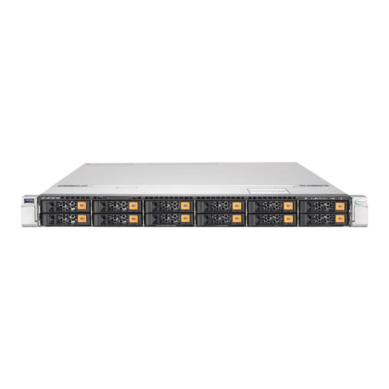
SuperServer SYS-1029U-TN12RV User's Manual Front Features The SC119UHTS-R1K22HP-T is a 1U chassis See the illustration below for the features included on the front of the chassis. Figure 1-2. Chassis Front View Front Chassis Features Item Feature Description Hot-swap 2.5" NVMe/SAS/SATA hard disk drive*... -
Page 13: Rear Features
Chapter 1: Introduction Rear Features The illustration below shows the features included on the rear of the chassis. Figure 1-4. Chassis Rear View Rear Chassis Features Item Feature Description Power Supply 1200W redundant power supply (p/n PWS-1K22A-1R) I/O Back Panel Rear I/O ports (see Section 4.3) Expansion Card Slot for expansion card (requires pre-installed riser cards) -
Page 14: Motherboard Layout
SuperServer SYS-1029U-TN12RV User's Manual 1.5 Motherboard Layout Below is a layout of the X11DPU-V with jumper, connector and LED locations shown. See the table on the following page for descriptions. For detailed descriptions, pinout information and jumper settings, refer to Chapter 4. -
Page 15: Quick Reference Table
NVMe SMBus (I2C) headers used for NVMe hot-plug SMBus clock & data connections JNVI2C1, JNVI2C2 (an SMCI-proprietary NVMe add-on card and cable are required; available for a Supermicro complete system only) JRK1 Intel® RAID Key Header for NVMe SSD JSD1, JSD2... - Page 16 SuperServer SYS-1029U-TN12RV User's Manual Description Status LED1 UID (Unit Identifier) LED Solid Blue: Unit Identified LEDM1 BMC Heartbeat LED Blinking Green: BMC Normal LEDPWR Onboard Power LED Solid Green: Power On Memory LED Description Status Memory Fault LEDs for Memory Module P1_A1/...
- Page 17 Chapter 1: Introduction NVMe drive bay 0 SATA drive Ultra Riser Card bays 0 - 11 Dual 25GbE ports NVMe (AOC-URN4 -M2TS) Ultra Riser drive bay 1 PCI-E x8 Slot Dual 10GbE ports ( AOC - URN4 - B2XT) NVMe drive bay 10 PCI-E x16 Slot (Internal) NVMe drive bay 11...
-
Page 18: Chapter 2 Server Installation
SuperServer 1029U-TN12RV User's Manual Chapter 2 Server Installation 2.1 Overview This chapter provides advice and instructions for mounting your system in a server rack. If your system is not already fully integrated with processors, system memory etc., refer to Chapter 4 for details on installing those specific components. Caution: Electrostatic Discharge (ESD) can damage electronic components. -
Page 19: Server Precautions
Chapter 2: Server Installation • In single rack installations, stabilizers should be attached to the rack. In multiple rack in- stallations, the racks should be coupled together. • Always make sure the rack is stable before extending a server or other component from the rack. -
Page 20: Circuit Overloading
SuperServer 1029U-TN12RV User's Manual Circuit Overloading Consideration should be given to the connection of the equipment to the power supply circuitry and the effect that any possible overloading of circuits might have on overcurrent protection and power supply wiring. Appropriate consideration of equipment nameplate ratings should be used when addressing this concern. -
Page 21: Installing The Server Into A Rack
Chapter 2: Server Installation 2.3 Installing the Server into a Rack This section provides information on installing the chassis into a rack unit with the rails provided. There are a variety of rack units on the market, which may mean that the assembly procedure differs slightly. -
Page 22: Installing The Optional Inner Rail Extensions
SuperServer 1029U-TN12RV User's Manual Installing the Optional Inner Rail Extensions Attaching the optional inner rail extensions allows you to pull the server farther out of the rack. Do not put downward force on the chassis when it is fully extended. Installing the Inner Rail Extensions 1. -
Page 23: Assembling The Outer Rails
Chapter 2: Server Installation Assembling the Outer Rails Each outer rail comes in two sections that must be assembled before mounting onto the rack. Assembling the Outer Rails 1. Identify the left and right outer rails by examining the ends, which bend outward. Match the left front outer rail with the left rear outer rail and the same for the right rails. -
Page 24: Installing The Outer Rails Onto The Rack
SuperServer 1029U-TN12RV User's Manual Installing the Outer Rails onto the Rack Each end of the assembled outer rail includes a bracket with square pegs to fit into your rack holes. If you have an older rack with round holes, these brackets must be removed, and you must use screws to secure the rail to the rack. -
Page 25: Installing The Chassis Into The Rack
Chapter 2: Server Installation Installing the Chassis into the Rack Installing the Chassis into the Rack 1. Slide the inner rail extensions into the front of the outer rails. 2. Push the chassis backward into the rack until it clicks into the locked position. Removing the Chassis from the Rack 1. -
Page 26: Installing The Server Into A Telco Rack
Chapter 2: Server Installation Installing the Server into a Telco Rack Two optional L-shaped brackets are needed to install the server to a telco (open type) rack. Installing the Server into a Telco Rack 1. Determine how far follow the server will extend out the front of the rack. Larger chassis should be positioned to balance the weight between front and back. -
Page 27: Chapter 3 Maintenance And Component Installation
Chapter 3: Maintenance and Component Installation Chapter 3 Maintenance and Component Installation This chapter provides instructions on installing and replacing main system components. To prevent compatibility issues, only use components that match the specifications and/or part numbers given. Installation or replacement of most components require that power first be removed from the system. -
Page 28: Motherboard Components
CPU socket cap is in place and that none of the socket pins are bent; otherwise, contact your retailer immediately. • Refer to the Supermicro website for updates on CPU support. • Please follow the instructions given in the ESD Warning section on the first page of this... -
Page 29: Intel Xeon Scalable-Sp And 2Nd Gen Intel Xeon Scalable-Sp Processors
Chapter 3: Maintenance and Component Installation Intel Xeon Scalable-SP and 2nd Gen Intel Xeon Scalable-SP Processors Intel Xeon Scalable-SP and 2nd Gen Intel Xeon Scalable-SP Processor Note: All graphics, drawings, and pictures shown in this manual are for illustration only. The components that came with your machine may or may not look exactly the same as those shown in this manual. -
Page 30: Overview Of The Processor Socket Assembly
SuperServer 1029U-TN12RV User's Manual Overview of the Processor Socket Assembly The processor socket assembly contains 1) Intel® Xeon® Scalable-SP or 2nd Generation Intel® Xeon® Scalable-SP processor, 2) the narrow processor clip, 3) the dust cover, and 4) the CPU socket. 1. -
Page 31: Overview Of The Processor Heatsink Module (Phm)
Chapter 3: Maintenance and Component Installation Overview of the Processor Heatsink Module (PHM) The Processor Heatsink Module (PHM) contains 1) a heatsink, 2) a narrow processor clip, and 3) Intel® Xeon® Scalable-SP or 2nd Generation Intel® Xeon® Scalable-SP processor. 1. Heatsink 2. -
Page 32: Attaching The Processor To The Narrow Processor Clip To Create The Processor Package Assembly
SuperServer 1029U-TN12RV User's Manual Attaching the Processor to the Narrow Processor Clip to Create the Processor Package Assembly To properly install the CPU into the narrow processor clip, please follow the steps below. 1. Locate pin 1 (notch A), which is the triangle located on the top of the narrow processor clip. -
Page 33: Attaching The Processor Package Assembly To The Heatsink To Form The Processor Heatsink Module (Phm)
Chapter 3: Maintenance and Component Installation Attaching the Processor Package Assembly to the Heatsink to Form the Processor Heatsink Module (PHM) After you have made a processor package assembly by following the instructions on the previous page, please follow the steps below to mount the processor package assembly onto the heatsink to create the Processor Heatsink Module (PHM). -
Page 34: Preparing The Cpu Socket For Installation
SuperServer 1029U-TN12RV User's Manual Preparing the CPU Socket for Installation This motherboard comes with the CPU socket pre-assembled in the factory. The CPU socket contains 1) a dust cover, 2) a socket bracket, 3) the CPU socket, and 4) a back plate. These components are pre-installed on the motherboard before shipping. -
Page 35: Installing The Processor Heatsink Module (Phm)
Chapter 3: Maintenance and Component Installation Installing the Processor Heatsink Module (PHM) 1. Once you have assembled the processor heatsink module (PHM) by following the instructions listed on page 29 or page 30, you are ready to install the processor heatsink module (PHM) into the CPU socket on the motherboard. -
Page 36: Removing The Processor Heatsink Module (Phm) From The Motherboard
SuperServer 1029U-TN12RV User's Manual Removing the Processor Heatsink Module (PHM) from the Motherboard Before removing the processor heatsink module (PHM), unplug power cord from the power outlet. 1. Using a T30 Torx-bit screwdriver, turn the screws on the PHM counterclockwise to loosen them from the socket, starting with screw marked #4 (in the sequence of 4, 3, 2, 2. -
Page 37: Memory Support And Installation
Chapter 3: Maintenance and Component Installation Memory Support and Installation Note: Check the Supermicro website for recommended memory modules. Exercise extreme care when installing or removing DIMM modules to prevent any damage. Memory Support The X11DPU-V supports up to 6 TB of 3DS Load Reduced DIMM (3DS LRDIMM), 3DS Registered DIMM (3DS RDIMM), or up to 3 TB of Load Registered DIMM (LRDIMM), with speeds up to 2933 MHz modules in 24 memory slots (*Notes below). -
Page 38: Ddr4 Memory Support For Intel Xeon Scalable-Sp Processors
8Rx4 4H-128GB 4H-256GB 2933 2933 2933 Notes: 1. 2933 MHz memory support in two-DIMMs per-channel (2DPC) configuration can be achieved by using memory purchased from Supermicro. 2. 2933 MHz memory is supported by 2nd Generation Intel Xeon Scalable-SP processors only. -
Page 39: Dimm Population Guidelines For Optimal Performance
Chapter 3: Maintenance and Component Installation DIMM Population Guidelines for Optimal Performance For optimal memory performance, follow the instructions listed in the tables below when populating memory modules. Key Parameters for DIMM Configuration Key Parameters for DIMM Configurations Parameters Possible Values Number of Channels 1, 2, 3, 4, 5, or 6 Number of DIMMs per Channel... -
Page 40: Dimm Population Table
SuperServer 1029U-TN12RV User's Manual DIMM Population Table Note: Unbalanced memory configuration decreases memory performance and is not recommended for Supermicro motherboards. Memory Population Table for the Motherboard Using Intel Xeon Scalable-SP and 2nd Gen Intel Xeon Scalable-SP Processors Memory Population Table for the X11DP Motherboard w/24 DIMM Slots... - Page 41 Chapter 3: Maintenance and Component Installation DCPMM Memory Population Tables for 2nd Gen Intel Xeon Scalable-SP Processors Note: Only 2nd Gen Intel Xeon Scalable-SP (82xx/62xx/52xx/42xx series) processors support DCPMM memory. Symmetric Population within 1 CPU Socket Channel P1-DIMMF1 P1-DIMMF2 P1-DIMME1 P1-DIMME2 Modes DIMMD1...
- Page 42 SuperServer 1029U-TN12RV User's Manual Validation Matrix (DDR4 DIMMs Validated w/DCPMM) DIMM Capacity (GB) Ranks Per DIMM DIMM Type & Data Width DRAM Density (Stack) 1Rx4 16GB 2Rx8 16GB RDIMM 2Rx4 16GB 32GB LRDIMM 4Rx4 64GB LRDIMM 3DS 8Rx4 (4H) 128GB...
-
Page 43: Dimm Installation
Chapter 3: Maintenance and Component Installation DIMM Installation 1. Insert the desired number of DIMMs into the memory slots, starting with P1-DIMM A1. For the system to work properly, please use memory modules of the same type and speed on the motherboard. BIOS X11DPU-V DESIGNED IN USA... -
Page 44: Pci Expansion Card Installation
SuperServer 1029U-TN12RV User's Manual PCI Expansion Card Installation The system includes two pre-installed riser cards (p/n RSC-R1UW-E8R and RSC-R1UW-2E16). Riser cards on chassis brackets allow you to add PCI expansion cards. • RSC-R1UW-E8R supports one standard size PCI-E x8 expansion card. •... -
Page 45: Internal Expansion Card
Chapter 3: Maintenance and Component Installation Internal Expansion Card The Ultra riser card that holds your LAN ports also offers another internal low profile card slot for Supermicro SAS only. Supermicro SAS Cards Part Number Description AOC-S3008L-L8e Std LP, 8 internal ports, 12 Gb/s per port, Gen 3,... -
Page 46: Removing The Ultra Riser Card
SuperServer 1029U-TN12RV User's Manual Removing the Ultra Riser Card To remove the Ultra riser card, use two hands. One hand lifts the mylar release tab and the other hand lifts at the PCI-E slot at the same time. Caution: Lifting at only one of these points may cause damage to connectors on the motherboard. -
Page 47: Motherboard Battery
Chapter 3: Maintenance and Component Installation Motherboard Battery The motherboard uses non-volatile memory to retain system information when system power is removed. This memory is powered by a lithium battery residing on the motherboard. Replacing the Battery Begin by removing power from the system as described in Section 3.1. 1. -
Page 48: Chassis Components
SuperServer 1029U-TN12RV User's Manual 3.4 Chassis Components Hard Drives The 1029U-TN12RV supports 12 hot-swappable 2.5" hard drives. The hard drives are mounted in drive carriers to simplify their installation and removal from the chassis. System power may remain on when removing carriers with drives installed. These carriers also help promote proper airflow for the drive bays. -
Page 49: Hot-Swap For Nvme Drives
Chapter 3: Maintenance and Component Installation Figure 3-15. Removing a Dummy Drive from the Carrier Note: Enterprise level hard disk drives are recommended for use in Supermicro chassis and servers. For information on recommended HDDs, visit the Supermicro website at https://www. -
Page 50: Checking The Temperature Of An Nvme Drive
SuperServer 1029U-TN12RV User's Manual Figure 3-16. IPMI Screenshot Replacing the Drive 1. Insert the replacement drive. 2. IPMI > Server Health > NVMe SSD 3. Select Device, Group and slot and click Insert. The drive Status LED indicator flashes red, then turns off. The Activity LED turns blue. Checking the Temperature of an NVMe Drive There are two ways to check using IPMI. -
Page 51: System Cooling
4. Unplug the fan cable from the motherboard and remove the failed fan from the chassis. 5. Replace the failed fan with an identical 4cm fan, available from Supermicro. 6. Push the new fan into the vacant space in the housing while making sure the arrows on the top of the fan (indicating air direction) point in the same direction as the arrows on the other fans. -
Page 52: Installing The Air Shroud
SuperServer 1029U-TN12RV User's Manual Installing the Air Shroud Air shrouds concentrate airflow to maximize fan efficiency. The motherboard air shroud does not require screws to install. Position the air shroud in the chassis as illustrated below. Figure 3-18. Installing the Air Shroud... -
Page 53: Power Supply
The Power Fail LED will illuminate and remain on until the failed unit has been replaced. Replacement units can be ordered directly from Supermicro. Replacing the Power Supply Begin by removing power from the failed power supply. -
Page 54: Chapter 4 Motherboard Connections
SuperServer 1029U-TN12RV User's Manual Chapter 4 Motherboard Connections This section describes the connections on the motherboard and provides pinout definitions. Note that depending on how the system is configured, not all connections are required. The LEDs on the motherboard are also described here. A motherboard layout indicating component locations may be found in Chapter 1. -
Page 55: Headers And Connectors
C2), used for PCI-E SMBus clock and data connections, provide hot-plug support via a dedicated SMBus interface. This feature is only available for a Supermicro complete system with an SMCI-proprietary NVMe add-on card and cable installed. See the table below for pin definitions. - Page 56 SuperServer 1029U-TN12RV User's Manual T-SGPIO3 Header A Serial General Purpose Input/Output header (T-SGPIO3) is located on the motherboard. This header is used to communicate with the enclosure management chip on the backplane. See the table below for pin definitions. SGPIO Header Pin Definitions Pin# Definition...
- Page 57 Intel® C621 chipset. In addition, it also has six S-SATA 3.0 ports (S-SATA0-3, S-SATA4/ S-SATA5) that are supported by the Intel® SCU. S-SATA4/S-SATA5 can be used with Supermicro SuperDOMs which are yellow SATA DOM connectors with power pins built in, and do not require external power cables. Supermicro SuperDOMs are backward-compatible with regular SATA HDDs or SATA DOMs that need external power cables.
-
Page 58: Rear I/O Ports
SuperServer 1029U-TN12RV User's Manual 4.3 Rear I/O Ports See the figure below for the locations and descriptions of the various I/O ports on the rear of the motherboard. BIOS DESIGNED IN USA X11DPU-V LICENSE REV:1.10 BAR CODE IPMI CODE CPU1 CPU2 Figure 4-1. - Page 59 Chapter 4: Motherboard Connections VGA Port One VGA port is located next to COM Port 1 on the I/O back panel. Use this connection for VGA display. Serial Port There is one COM port (COM1) on the I/O back panel on the motherboard. This COM port provides serial communication support.
- Page 60 Note: UID can also be triggered via IPMI on the motherboard. For more information on IPMI, please refer to the IPMI User's Guide posted on our website at http://www.supermicro.com. UID Switch...
-
Page 61: Front Control Panel
These connectors are designed specifically for use IPMI_LAN USB0/1 (3.0) COM1 JUIDB2 with Supermicro chassis. See the figure below for the descriptions of the front control panel LED1 LEDM1 buttons and LED indicators. - Page 62 SuperServer 1029U-TN12RV User's Manual NMI Button The non-maskable interrupt button header is located on pins 19 and 20 of JF1. Refer to the table below for pin definitions. NMI Button Pin Definitions (JF1) Pin# Definition Ground Power LED The Power LED connection is located on pins 15 and 16 of JF1. Refer to the table below for pin definitions.
- Page 63 Chapter 4: Motherboard Connections Power Fail LED The Power Fail LED connection is located on pins 5 and 6 of JF1. Refer to the table below for pin definitions. Power Fail LED Pin Definitions (JF1) Pin# Definition 3.3V PWR Supply Fail UID/OH/Fan Fail/PWR Fail LED Connect an LED cable to pins 7 and 8 of the Front Control Panel (JF1) to use UID/Overheat/ Fan Fail/Power Fail LED connections.
-
Page 64: Jumpers
SuperServer 1029U-TN12RV User's Manual 4.5 Jumpers Explanation of Jumpers To modify the operation of the motherboard, jumpers are used to choose between optional settings. Jumpers create shorts between two pins to change the function associated with it. Pin 1 is identified with a square solder pad on the printed circuit board. See the motherboard layout page for jumper locations. -
Page 65: Led Indicators
Chapter 4: Motherboard Connections Watch Dog JWD1 controls the Watch Dog function. Watch Dog is a monitor that can reboot the system when a software application hangs. Jumping pins 1-2 will cause Watch Dog to reset the system if an application hangs. Jumping pins 2-3 will generate a non-maskable interrupt signal for the application that hangs. - Page 66 SuperServer 1029U-TN12RV User's Manual Onboard Power LED LEDPWR is an Onboard Power LED. When this LED is lit, it means that power is present on the motherboard. Be sure to turn off the system and unplug the power cord(s) before removing or installing components.
-
Page 67: Chapter 5 Software
1. Create a method to access the MS Windows installation ISO file. That can be a USB flash or media drive. 2. Retrieve the proper RST/RSTe driver. Go to the Supermicro web page for your motherboard and click on "Download the Latest Drivers and Utilities", select the proper driver, and copy it to a USB flash drive. - Page 68 SuperServer 1029U-TN12RV User's Manual 4. During Windows Setup, continue to the dialog where you select the drives on which to install Windows. If the disk you want to use is not listed, click on “Load driver” link at the bottom left corner. Figure 5-2.
-
Page 69: Driver Installation
The Supermicro website contains drivers and utilities for your system at https://www. supermicro.com/wdl/driver. Some of these must be installed, such as the chipset driver. After accessing the website, go into the CDR_Images (in the parent directory of the above link) and locate the ISO file for your motherboard. Download this file to to a USB flash or media drive. -
Page 70: Superdoctor ® 5
5.3 SuperDoctor ® The Supermicro SuperDoctor 5 is a program that functions in a command-line or web-based interface for Windows and Linux operating systems. The program monitors such system health information as CPU temperature, system voltages, system power consumption, fan speed, and provides alerts via email or Simple Network Management Protocol (SNMP). -
Page 71: Bmc
This can be found on a sticker on the chassis and a sticker on the motherboard. The sticker also displays the BMC MAC address. If necessary, the password can be reset using the Supermicro IPMICFG tool. Figure 5-5. BMC Password Label... -
Page 72: Chapter 6 Uefi Bios
SuperServer 1029U-TN12RV User's Manual Chapter 6 UEFI BIOS 6.1 Introduction This chapter describes the AMIBIOS™ Setup utility for the X11DPU-V motherboard. The BIOS is stored on a chip and can be easily upgraded using a flash program. Note: Due to periodic changes to the BIOS, some settings may have been added or deleted and might not yet be recorded in this manual. -
Page 73: Main Setup
Note: The time is in the 24-hour format. For example, 5:30 P.M. appears as 17:30:00. The date's default value is the BIOS build after RTC reset. Supermicro X11DPU BIOS Version This feature displays the version of the BIOS ROM used in the system. -
Page 74: Advanced Setup Configurations
SuperServer 1029U-TN12RV User's Manual Memory Information Total Memory This feature displays the total size of memory available in the system. 6.3 Advanced Setup Configurations Use the arrow keys to select Boot Setup and press <Enter> to access the submenu items. Warning: Take caution when changing the Advanced settings. - Page 75 Chapter 6: UEFI BIOS Bootup NumLock State Use this feature to set the Power-on state for the <Numlock> key. The options are On and Off. Wait For "F1" If Error Use this feature to force the system to wait until the 'F1' key is pressed if an error occurs. The options are Disabled and Enabled.
- Page 76 SuperServer 1029U-TN12RV User's Manual Power Button Function This feature controls how the system shuts down when the power button is pressed. Select 4 Seconds Override for the user to power off the system after pressing and holding the power button for 4 seconds or longer. Select Instant Off to instantly power off the system as soon as the user presses the power button.
- Page 77 Chapter 6: UEFI BIOS Execute Disable Bit (Available if supported by the OS & the CPU) Select Enable to enable the Execute-Disable Bit which will allow the processor to designate areas in the system memory where an application code can execute and where it cannot, thus preventing a worm or a virus from flooding illegal codes to overwhelm the processor or damage the system during an attack.
- Page 78 SuperServer 1029U-TN12RV User's Manual Extended APIC (Extended Advanced Programmable Interrupt Controller) Select Enable to use the extended APIC (Advanced Programmable Interrupt Control) support to enhance power management. The options are Disable and Enable. AES-NI Select Enable to use the Intel® Advanced Encryption Standard (AES) New Instructions (NI) to ensure data security.
- Page 79 Chapter 6: UEFI BIOS Hardware PM State Control Hardware P-States This feature enables the hardware P-States support. The options are Disable, Native Mode, Out of Band Mode, and Native Mode with No Legacy Support. CPU C State Control Autonomous Core C-State Use this feature to enable the autonomous core C-State control.
- Page 80 SuperServer 1029U-TN12RV User's Manual Chipset Configuration Warning: Setting the wrong values in the following features may cause the system to malfunc- tion. North Bridge This feature allows the user to configure the following North Bridge settings. UPI Configuration UPI Configuration The following information will be displayed: •...
- Page 81 Chapter 6: UEFI BIOS Isoc Mode Select Enable to enable Isochronous support to meet QoS (Quality of Service) require- ments. This feature is especially important for Virtualization Technology. The options are Disable, Enable, and Auto. Memory Configuration Integrated Memory Controller (iMC) Enforce POR Select Enable to enforce POR restrictions on DDR4 frequency and voltage programming.
- Page 82 SuperServer 1029U-TN12RV User's Manual Memory Topology The following information will be displayed: P1 DIMMA1/P1 DIMMB1/P1 DIMMC1/P1 DIMMD1/P1 DIMME1/P1 DIMMF1 Memory RAS (Reliability_Availability_Serviceability) Configuration Memory RAS Configuration Setup Use this submenu to configure the following Memory RAS settings. Static Virtual Lockstep Mode Select Enable to support the static virtual lockstep mode.
- Page 83 Chapter 6: UEFI BIOS ADDDC Sparing Adaptive Double Device Data Correction (ADDDC) Sparing detects the predetermined threshold for correctable errors, copying the contents of the failing DIMM to spare memory. The failing DIMM or memory rank will then be disabled. The options are Dis- able and Enable.
- Page 84 SuperServer 1029U-TN12RV User's Manual MCP0 (IIO PCIe Br4) This feature configures the PCI-E port Bifurcation setting for a PCI-E port specified by the user. The options are x16 and Auto. MCP1 (IIO PCIe Br5) This feature configures the PCI-E port Bifurcation setting for a PCI-E port specified by the user.
- Page 85 Chapter 6: UEFI BIOS AOC-URN4-m2TS NVME0 (Available when the device is detected by the system) Link Speed This feature allows the user to select PCI-E support for the device installed in the system. The options are Auto, Gen 1 (2.5 GT/s), Gen 2 (5 GT/s), and Gen 3 (8 GT/s). PCI-E Port Link Status PCI-E Port Link Max PCI-E Port Link Speed...
- Page 86 SuperServer 1029U-TN12RV User's Manual PCI-E Port Link Status PCI-E Port Link Max PCI-E Port Link Speed PCI-E Port Max Payload Size Select Auto for the system BIOS to automatically set the maximum payload value for a PCI-E device to enhance system performance. The options are 128B, 256B, and Auto.
- Page 87 Chapter 6: UEFI BIOS CPU2 Configuration IOU0 (IIO PCIe Br1) This feature configures the PCI-E port Bifurcation setting for a PCI-E port specified by the user. The options are x4x4x4x4, x4x4x8, x8x4x4, x8x8, x16, and Auto. IOU1 (IIO PCIe Br2) This feature configures the PCI-E port Bifurcation setting for a PCI-E port specified by the user.
- Page 88 SuperServer 1029U-TN12RV User's Manual P2_NVMe0 Link Speed This feature allows the user to select PCI-E support for the device installed in the system. The options are Auto, Gen 1 (2.5 GT/s), Gen 2 (5 GT/s), and Gen 3 (8 GT/s).. PCI-E Port Link Status PCI-E Port Link Max PCI-E Port Link Speed...
- Page 89 Chapter 6: UEFI BIOS PCI-E Port Max Payload Size - Select Auto for the system BIOS to automatically set the maximum payload value for a PCI-E device to enhance system performance. The options are 128B, 256B, and Auto. RSC-R1UW-2E16 SLOT2 ...
- Page 90 SuperServer 1029U-TN12RV User's Manual Intel® VT for Directed I/O (VT-d) Intel VT for Directed I/O (VT-d) ® Select Enable to use Intel® Virtualization Technology support for Direct I/O VT-d support by reporting the I/O device assignments to the VMM (Virtual Machine Monitor) through the DMAR ACPI Tables.
- Page 91 Chapter 6: UEFI BIOS Intel® VMD for Volume Management Device on CPU1 VMD Config for PStack0 Intel® VMD for Volume Management Device Select Enable to use the Intel® Volume Management Device Technology for this stack. The options are Disable and Enable. *If the feature, Intel®...
- Page 92 SuperServer 1029U-TN12RV User's Manual AOC-URN4-m2TS NVME2 VMD (Available when the device is detected by the system) Select Enable to use the Intel® Volume Management Device Technology for this device. The options are Disable and Enable. AOC-URN4-m2TS NVME3 VMD (Available when the device is detected by the system) Select Enable to use the Intel®...
- Page 93 Chapter 6: UEFI BIOS RSC-R1UW-E8R SLOT1 VMD (Available when the device is detected by the system) Select Enable to use the Intel® Volume Management Device Technology for this device. The options are Disable and Enable. P2_NVMe0 VMD (Available when the device is detected by the system) Select Enable to use the Intel®...
- Page 94 SuperServer 1029U-TN12RV User's Manual RSC-R1UW-2E16 SLOT2 VMD (Available when the device is detected by the system) Select Enable to use the Intel® Volume Management Device Technology for this device. The options are Disable and Enable. Hot Plug Capable (Available when the device is detected by the system) Use this feature to enable the hot plug support for PCIe root ports 3A~3D.
- Page 95 Chapter 6: UEFI BIOS Server ME Configuration This feature displays the following system ME configuration settings. • Operational Firmware Version • Backup Firmware Version • Recovery Firmware Version • ME Firmware Status #1 • ME Firmware Status #2 • Current State •...
- Page 96 SuperServer 1029U-TN12RV User's Manual Hot Plug (SATA Port 0~ Port 7) Select Enabled to enable a SATA port specified by the user. The options are Disable and Enable. Spin Up Device (SATA Port 0~ Port 7) On an edge detect from 0 to 1, set this feature to allow the PCH to initialize the device. The options are Disable and Enable.
- Page 97 Chapter 6: UEFI BIOS SATA Device Type (SATA Port 0~ Port 7) Use this feature to specify if the SATA port specified by the user should be connected to a Solid State drive or a Hard Disk Drive. The options are Hard Disk Drive and Solid State Drive.
- Page 98 SuperServer 1029U-TN12RV User's Manual sSATA Device Type (sSATA Port 0~ Port 5) Use this feature to specify if the SATA port specified by the user should be connected to a Solid State drive or a Hard Disk Drive. The options are Hard Disk Drive and Solid State Drive.
- Page 99 Chapter 6: UEFI BIOS Above 4G Decoding (Available if the system supports 64-bit PCI decoding) Select Enabled to decode a PCI device that supports 64-bit in the space above 4G Address. The options are Disabled and Enabled. SR-IOV Support Use this feature to enable or disable Single Root IO Virtualization support. The options are Disabled and Enabled.
- Page 100 SuperServer 1029U-TN12RV User's Manual Select Disabled to deactivate the selected slot, Legacy to activate the slot in legacy mode, and EFI to activate the slot in EFI mode. The options are Disabled, Legacy, and EFI. Onboard LAN Option ROM Type Select an option to enable Option ROM support to boot the computer using a device specified by the user.
- Page 101 Chapter 6: UEFI BIOS Ipv4 HTTP Support Select Enabled to enable Ipv4 HTTP boot support. The options are Disabled and Enabled. Ipv6 PXE Support Select Enabled to enable Ipv6 PXE boot support. The options are Disabled and Enabled. Ipv6 HTTP Support Select Enabled to enable Ipv6 HTTP boot support.
- Page 102 SuperServer 1029U-TN12RV User's Manual Serial Port 2 Configuration Serial Port 2 Configuration This submenu allows the user the configure settings of Serial Port 2. Serial Port 2 Select Enabled to enable the selected onboard serial port. The options are Disabled and Enabled.
- Page 103 Chapter 6: UEFI BIOS Terminal Type This feature allows the user to select the target terminal emulation type for Console Redirection. Select VT100 to use the ASCII Character set. Select VT100+ to add color and function key support. Select ANSI to use the Extended ASCII Character Set. Select VT-UTF8 to use UTF8 encoding to map Unicode characters into one or more bytes.
- Page 104 SuperServer 1029U-TN12RV User's Manual Resolution 100x31 Select Enabled for extended-terminal resolution support. The options are Disabled and Enabled. Legacy OS Redirection Resolution Use this feature to select the number of rows and columns used in Console Redirection for legacy OS support. The options are 80x24 and 80x25. Putty KeyPad This feature selects the settings for the function keys and the key pad used for Putty, which is a terminal emulator designed for the Windows OS.
- Page 105 Chapter 6: UEFI BIOS Bits Per second Use this feature to set the transmission speed for a serial port used in Console Redirection. Make sure that the same speed is used in the host computer and the client computer. A lower transmission speed may be required for long and busy lines.
- Page 106 SuperServer 1029U-TN12RV User's Manual Putty KeyPad This feature selects the settings for the function keys and the key pad used for Putty, which is a terminal emulator designed for the Windows OS. The options are VT100, LINUX, XTERMR6, SC0, ESCN, and VT400. Redirection After BIOS POST Use this feature to enable or disable legacy console redirection after BIOS POST.
- Page 107 Chapter 6: UEFI BIOS Bits Per second This feature sets the transmission speed for a serial port used in Console Redirection. Make sure that the same speed is used in both host computer and the client computer. A lower transmission speed may be required for long and busy lines. The options are 9600, 19200, 57600, and 115200 (bits per second).
- Page 108 SuperServer 1029U-TN12RV User's Manual *If the feature above is set to Enable, the following features will become available for user's configuration: The following Platform Configuration Register information will be displayed: • Active PCR banks • Available PCR banks SHA-1 PCR Bank Use this feature to disable or enable the SHA-1 Platform Configuration Register (PCR) bank for the installed TPM device.
- Page 109 Chapter 6: UEFI BIOS HTTP Boot Configuration Use this feature to configure HTTP Boot settings for your system. HTTP Boot One Time If this feature is set to Enabled, the system will automatically boot into the HttpBoot setting that has been previously configured when it is powered up the first time. The options are Disabled and Enabled.
- Page 110 SuperServer 1029U-TN12RV User's Manual Delete Certification If this feature is set to Enable, the certificate enrolled in the system will be deleted. The options are Enable and Disable. iSCSi Configuration iSCSI Initiator Name This feature allows the user to enter the unique name of the iSCSI Initiator in IQN format. Once the name of the iSCSI Initiator is entered into the system, configure the proper settings for the following features.
- Page 111 Chapter 6: UEFI BIOS DIMM ID 0x0001 Press <Enter> and the following information regarding this DIMM will be displayed. View settings or select an action below. DIMM UID 8089-A2-1837-0000115D DIMM handle 0x0001 DIMM physical ID 0x0019 Manageability state [Manageable] Health state [Healthy] Health state reason None...
- Page 112 SuperServer 1029U-TN12RV User's Manual Device locator P1-DIMMA2 Subsystem revision ID 0x18 Interface format code 0x0301 (Non-Energy Backed Byte Addressable) Manufacturing info valid Manufacturing date 18-37 Manufacturing location 0xA2 Memory type Logical Non-Volatile Device Memory bank label P0_Node0_Channel0_Dimm1 Data width label [b] Total width [b] Speed [MHz] 2666...
- Page 113 Chapter 6: UEFI BIOS Package spares available 1 Configuration status [Valid] SKU violation ARS status [Completed] Overwrite DIMM status [Not started] Last shutdown time Fri Dec 21 17:29:23 UTC 2018 First fast refresh Viral policy enable Viral state Latched Last shutdown status PM ADR Command Received, DDRT Power Fail Command Received, PMIC 12V/DDRT 1.2V Power Loss (PLI), Controller's FW State Flush Complete, Write Data Flush Complete, PM Idle Received (Note: All DCPMM items and strings displayed on the BIOS screen are provided by...
- Page 114 SuperServer 1029U-TN12RV User's Manual DIMM ID 0x0101 Press <Enter> and the following information regarding this DIMM will be displayed. View settings or select an action below. DIMM UID 8089-A2-1837-00000B35 DIMM handle 0x0101 DIMM physical ID 0x0021 Manageability state [Manageable] Health state [Healthy] Health state reason None...
- Page 115 Chapter 6: UEFI BIOS Device locator P1-DIMMD2 Subsystem revision ID 0x18 Interface format code 0x0301 (Non-Energy Backed Byte Addressable) Manufacturing info valid 1 Manufacturing date 18-37 Manufacturing location 0xA2 Memory type Logical Non-Volatile Device Memory bank label P0_Node1_Channel0_Dimm1 Data width label [b] Total width [b] Speed [MHz] 2666...
- Page 116 SuperServer 1029U-TN12RV User's Manual Package spares available 1 Configuration status [Valid] SKU violation ARS status [Completed] Overwrite DIMM status [Not started] Last shutdown time Fri Dec 21 17:29:23 UTC 2018 First fast refresh Viral policy enable Viral state Latched Last shutdown status PM S5 Received, PMIC 12V/DDRT 1.2V Power Loss (PLI), Controller's FW State Flush Complete, Write Data Flush Complete, PM Idle Received (Note: All DCPMM items and strings displayed on the BIOS screen are provided by...
- Page 117 Chapter 6: UEFI BIOS DIMM ID 0x0011 Press <Enter> and the following information regarding this DIMM will be displayed. View settings or select an action below. DIMM UID 8089-A2-1837-00000B34 DIMM handle 0x0011 DIMM physical ID 0x001B Manageability state [Manageable] Health state [Healthy] Health state reason None...
- Page 118 SuperServer 1029U-TN12RV User's Manual Device locator P1-DIMMB2 Subsystem revision ID 0x18 Interface format code 0x0301 (Non-Energy Backed Byte Addressable) Manufacturing info valid 1 Manufacturing date 18-37 Manufacturing location 0xA2 Memory type Logical Non-Volatile Device Memory bank label P0_Node0_Channel1_Dimm1 Data width label [b] Total width [b] Speed [MHz] 2666...
- Page 119 Chapter 6: UEFI BIOS Package spares available 1 Configuration status [Valid] SKU violation ARS status [Completed] Overwrite DIMM status [Not started] Last shutdown time Fri Dec 21 17:29:23 UTC 2018 First fast refresh Viral policy enable Viral state Latched Last shutdown status PM S5 Received, PMIC 12V/DDRT 1.2V Power Loss (PLI), Controller's FW State Flush Complete, Write Data Flush Complete, PM Idle Received (Note: All DCPMM items and strings displayed on the BIOS screen are provided by...
- Page 120 SuperServer 1029U-TN12RV User's Manual DIMM ID 0x0111 Press <Enter> and the following information regarding this DIMM will be displayed. View settings or select an action below. DIMM UID 8089-A2-1837-0000110C DIMM handle 0x0111 DIMM physical ID 0x0023 Manageability state [Manageable] Health state [Healthy] Health state reason None...
- Page 121 Chapter 6: UEFI BIOS Device locator P1-DIMME2 Subsystem revision ID 0x18 Interface format code 0x0301 (Non-Energy Backed Byte Addressable) Manufacturing info valid Manufacturing date 18-37 Manufacturing location 0xA2 Memory type Logical Non-Volatile Device Memory bank label P0_Node1_Channel1_Dimm1 Data width label [b] Total width [b] Speed [MHz] 2666...
- Page 122 SuperServer 1029U-TN12RV User's Manual Package sparing enabled 1 Package spares available 1 Configuration status [Valid] SKU violation ARS status [Completed] Overwrite DIMM status [Not started] Last shutdown time Fri Dec 21 17:29:23 UTC 2018 First fast refresh Viral policy enable Viral state Latched Last shutdown status PM S5 Received, PMIC 12V/DDRT 1.2V Power Loss (PLI), Controller's FW State Flush Complete, Write Data Flush Complete,...
- Page 123 Chapter 6: UEFI BIOS DIMM ID 0x0021 Press <Enter> and the following information regarding this DIMM will be displayed. View settings or select an action below. DIMM UID 8089-A2-1837-00000B2E DIMM handle 0x0021 DIMM physical ID 0x001D Manageability state [Manageable] Health state [Healthy] Health state reason None...
- Page 124 SuperServer 1029U-TN12RV User's Manual Subsystem device ID 0x97A Device locator P1-DIMMC2 Subsystem revision ID 0x18 Interface format code 0x0301 (Non-Energy Backed Byte Addressable) Manufacturing info valid Manufacturing date 18-37 Manufacturing location 0xA2 Memory type Logical Non-Volatile Device Memory bank label P0_Node0_Channel2_Dimm1 Data width label [b] Total width [b]...
- Page 125 Chapter 6: UEFI BIOS Package sparing enabled 1 Package spares available 1 Configuration status [Valid] SKU violation ARS status [Completed] Overwrite DIMM status [Not started] Last shutdown time Fri Dec 21 17:29:23 UTC 2018 First fast refresh Viral policy enable Viral state Latched Last shutdown status PM S5 Received, PMIC 12V/DDRT 1.2V Power Loss (PLI), Controller's FW State Flush Complete, Write Data Flush Complete,...
- Page 126 SuperServer 1029U-TN12RV User's Manual DIMM ID 0x0121 Press <Enter> and the following information regarding this DIMM will be displayed. View settings or select an action below. DIMM UID 8089-A2-1837-000010AE DIMM handle 0x0121 DIMM physical ID 0x0025 Manageability state [Manageable] Health state [Healthy] Health state reason None...
- Page 127 Chapter 6: UEFI BIOS Device locator P1-DIMMF2 Subsystem revision ID 0x18 Interface format code 0x0301 (Non-Energy Backed Byte Addressable) Manufacturing info valid Manufacturing date 18-37 Manufacturing location 0xA2 Memory type Logical Non-Volatile Device Memory bank label P0_Node1_Channel2_Dimm1 Data width label [b] Total width [b] Speed [MHz] 2666...
- Page 128 SuperServer 1029U-TN12RV User's Manual Package spares available 1 Configuration status [Valid] SKU violation ARS status [Completed] Overwrite DIMM status [Not started] Last shutdown time Fri Dec 21 17:29:23 UTC 2018 First fast refresh Viral policy enable Viral state Latched Last shutdown status PM S5 Received, PMIC 12V/DDRT 1.2V Power Loss (PLI), Controller's FW State Flush Complete, Write Data Flush Complete, PM Idle Received (Note: All DCPMM items and strings displayed on the BIOS screen are provided by...
- Page 129 Chapter 6: UEFI BIOS DIMM ID 0x1001 Press <Enter> and the following information regarding this DIMM will be displayed. View settings or select an action below. DIMM UID 8089-A2-1837-0000111C DIMM handle 0x1001 DIMM physical ID 0x0029 Manageability state [Manageable] Health state [Healthy] Health state reason None...
- Page 130 SuperServer 1029U-TN12RV User's Manual Device locator P2-DIMMA2 Subsystem revision ID 0x18 Interface format code 0x0301 (Non-Energy Backed Byte Addressable) Manufacturing info valid Manufacturing date 18-37 Manufacturing location 0xA2 Memory type Logical Non-Volatile Device Memory bank label P1_Node0_Channel0_Dimm1 Data width label [b] Total width [b] Speed [MHz] 2666...
- Page 131 Chapter 6: UEFI BIOS Package spares available 1 Configuration status [Valid] SKU violation ARS status [Completed] Overwrite DIMM status [Not started] Last shutdown time Fri Dec 21 17:29:23 UTC 2018 First fast refresh Viral policy enable Viral state Latched Last shutdown status PM S5 Received, PMIC 12V/DDRT 1.2V Power Loss (PLI), Controller's FW State Flush Complete, Write Data Flush Complete, PM Idle Received (Note: All DCPMM items and strings displayed on the BIOS screen are provided by...
- Page 132 SuperServer 1029U-TN12RV User's Manual DIMM ID 0x1101 Press <Enter> and the following information regarding this DIMM will be displayed. View settings or select an action below. DIMM UID 8089-A2-1837-00001038 DIMM handle 0x1101 DIMM physical ID 0x0031 Manageability state [Manageable] Health state [Healthy] Health state reason None...
- Page 133 Chapter 6: UEFI BIOS Device locator P2-DIMMD2 Subsystem revision ID 0x18 Interface format code 0x0301 (Non-Energy Backed Byte Addressable) Manufacturing info valid Manufacturing date 18-37 Manufacturing location 0xA2 Memory type Logical Non-Volatile Device Memory bank label P1_Node1_Channel0_Dimm1 Data width label [b] Total width [b] Speed [MHz] 2666...
- Page 134 SuperServer 1029U-TN12RV User's Manual Package spares available 1 Configuration status [Valid] SKU violation ARS status [Completed] Overwrite DIMM status [Not started] Last shutdown time Fri Dec 21 17:29:23 UTC 2018 First fast refresh Viral policy enable Viral state Latched Last shutdown status PM S5 Received, PMIC 12V/DDRT 1.2V Power Loss (PLI), Controller's FW State Flush Complete, Write Data Flush Complete, PM Idle Received (Note: All DCPMM items and strings displayed on the BIOS screen are provided by...
- Page 135 Chapter 6: UEFI BIOS DIMM ID 0x1011 Press <Enter> and the following information regarding this DIMM will be displayed. View settings or select an action below. DIMM UID 8089-A2-1837-00000AA5 DIMM handle 0x1011 DIMM physical ID 0x002B Manageability state [Manageable] Health state [Healthy] Health state reason None...
- Page 136 SuperServer 1029U-TN12RV User's Manual Device locator P2-DIMMB2 Subsystem revision ID 0x18 Interface format code 0x0301 (Non-Energy Backed Byte Addressable) Manufacturing info valid Manufacturing date 18-37 Manufacturing location 0xA2 Memory type Logical Non-Volatile Device Memory bank label P1_Node0_Channel1_Dimm1 Data width label [b] Total width [b] Speed [MHz] 2666...
- Page 137 Chapter 6: UEFI BIOS Package spares available 1 Configuration status [Valid] SKU violation ARS status [Completed] Overwrite DIMM status [Not started] Last shutdown time Fri Dec 21 17:29:23 UTC 2018 First fast refresh Viral policy enable Viral state Latched Last shutdown status PM S5 Received, PMIC 12V/DDRT 1.2V Power Loss (PLI), Controller's FW State Flush Complete, Write Data Flush Complete, PM Idle Received (Note: All DCPMM items and strings displayed on the BIOS screen are provided by...
- Page 138 SuperServer 1029U-TN12RV User's Manual DIMM ID 0x1111 Press <Enter> and the following information regarding this DIMM will be displayed. View settings or select an action below. DIMM UID 8089-A2-1837-000000E3A DIMM handle 0x1111 DIMM physical ID 0x0033 Manageability state [Manageable] Health state [Healthy] Health state reason None...
- Page 139 Chapter 6: UEFI BIOS Device locator P2-DIMME2 Subsystem revision ID 0x18 Interface format code 0x0301 (Non-Energy Backed Byte Addressable) Manufacturing info valid Manufacturing date 18-37 Manufacturing location 0xA2 Memory type Logical Non-Volatile Device Memory bank label P1_Node1_Channel1_Dimm1 Data width label [b] Total width [b] Speed [MHz] 2666...
- Page 140 SuperServer 1029U-TN12RV User's Manual Package spares available 1 Configuration status [Valid] SKU violation ARS status [Completed] Overwrite DIMM status [Not started] Last shutdown time Fri Dec 21 17:29:23 UTC 2018 First fast refresh Viral policy enable Viral state Latched Last shutdown status PM S5 Received, PMIC 12V/DDRT 1.2V Power Loss (PLI), Controller's FW State Flush Complete, Write Data Flush Complete, PM Idle Received (Note: All DCPMM items and strings displayed on the BIOS screen are provided by...
- Page 141 Chapter 6: UEFI BIOS DIMM ID 0x1021 Press <Enter> and the following information regarding this DIMM will be displayed. View settings or select an action below. DIMM UID 8089-A2-1837-0000118C DIMM handle 0x1021 DIMM physical ID 0x002D Manageability state [Manageable] Health state [Healthy] Health state reason None...
- Page 142 SuperServer 1029U-TN12RV User's Manual Device locator P2-DIMMC2 Subsystem revision ID 0x18 Interface format code 0x0301 (Non-Energy Backed Byte Addressable) Manufacturing info valid Manufacturing date 18-37 Manufacturing location 0xA2 Memory type Logical Non-Volatile Device Memory bank label P1_Node1_Channel2_Dimm1 Data width label [b] Total width [b] Speed [MHz] 2666...
- Page 143 Chapter 6: UEFI BIOS Package spares available 1 Configuration status [Valid] SKU violation ARS status [Completed] Overwrite DIMM status [Not started] Last shutdown time Fri Dec 21 17:29:23 UTC 2018 First fast refresh Viral policy enable Viral state Latched Last shutdown status PM S5 Received, PMIC 12V/DDRT 1.2V Power Loss (PLI), Controller's FW State Flush Complete, Write Data Flush Complete, PM Idle Received (Note: All DCPMM items and strings displayed on the BIOS screen are provided by...
- Page 144 SuperServer 1029U-TN12RV User's Manual DIMM ID 0x1121 Press <Enter> and the following information regarding this DIMM will be displayed. View settings or select an action below. DIMM UID 8089-A2-1837-00000BB2 DIMM handle 0x1211 DIMM physical ID 0x0035 Manageability state [Manageable] Health state [Healthy] Health state reason None...
- Page 145 Chapter 6: UEFI BIOS Device locator P2-DIMMF2 Subsystem revision ID 0x18 Interface format code 0x0301 (Non-Energy Backed Byte Addressable) Manufacturing info valid Manufacturing date 18-37 Manufacturing location 0xA2 Memory type Logical Non-Volatile Device Memory back label P1_Node1_Channel2_Dimm1 Data width label [b] Total width [b] Speed [MHz] 2666...
- Page 146 SuperServer 1029U-TN12RV User's Manual Package spares available 1 Configuration status [Valid] SKU violation ARS status [Completed] Overwrite DIMM status [Not started] Last shutdown time Fri Dec 21 17:29:23 UTC 2018 First fast refresh Viral policy enable Viral state Latched Last shutdown status PM S5 Received, PMIC 12V/DDRT 1.2V Power Loss (PLI), Controller's FW State Flush Complete, Write Data Flush Complete, PM Idle Received (Note: All DCPMM items and strings displayed on the BIOS screen are provided by...
- Page 147 Chapter 6: UEFI BIOS Monitor health Current non-critical threshold status Controller temperature: within the non-critical threshold on all DIMMs. Media temperature: within the non-critical threshold on all DIMMs. Percentage remaining: within the non-critical threshold on all DIMMs. Modify non-critical thresholds Controller temperature [C] Use this feature to set controller temperature in Celsius.
- Page 148 SuperServer 1029U-TN12RV User's Manual Configure security Specify the security settings on ALL the DIMMs. State: [Disabled] [Disabled, Frozen] will be displayed after pressing the following feature, Frozen lock. Enable security Use this feature to enable security by entering a new passphrase. Press <Enter> to type in a new passphrase with at least one character.
- Page 149 Chapter 6: UEFI BIOS No goal configuration specified. Create goal config Use this submenu to create goal configuration of DIMM regions. Select the scope of the new region then set the desired sizes. Create goal config for: Use this feature to select target to create goal configuration. The options are Platform and Socket.
- Page 150 SuperServer 1029U-TN12RV User's Manual 0x00000101 Healthy Use this feature to display details for or modify selected namespace. View details for or modify selected namespace. UUID 66B9E696-0E38-47B3-81 5E-99FFAFC26A23 0x00000101 Name Press <Enter> to type in a name of namespace. Region 1 Health [Healthy] Mode [None] Block size [4096 B]...
- Page 151 Chapter 6: UEFI BIOS Region ID This feature displays the region ID on which to create namespace. Mode Use this feature to set namespace mode. The options are None and Sector. The op- tion, None, is for raw access only. Set this feature to Sector to guarantee powerfail write automicity via a block translation table (BTT) Capacity input The options are Remaining and Manual.
- Page 152 SuperServer 1029U-TN12RV User's Manual Reserved capacity: 5.4 GiB Back to main menu Diagnostics Perform diagnostic tests on DIMMS. Choose diagnostics type: Quick diagnostics Select Enabled to perform quick diagnostics test. The options are Disabled and Enabled. DIMM ID 0x0001 Select Enabled to enable the diagnostics procedure for this DIMM. The options are Disabled and Enabled.
- Page 153 Chapter 6: UEFI BIOS DIMM ID 0x0021 Select Enabled to enable the diagnostics procedure for this DIMM. The options are Disabled and Enabled. DIMM ID 0x0121 Select Enabled to enable the diagnostics procedure for this DIMM. The options are Disabled and Enabled.
- Page 154 SuperServer 1029U-TN12RV User's Manual TestName: Config State: Ok Message: The platform configuration check succeeded. TestName: Security State: Ok Message: The security check succeeded. TestName: FW State: Ok Message: The firmware consistency and settings check succeeded. Back to main menu Preferences Use this submenu to display and/or modify user preferences.
- Page 155 Chapter 6: UEFI BIOS Back to main menu Driver Health This submenu displays the health status of the drivers and controllers as detected by the system. The following information is displayed. Intel(R) DCPMM 1.0.0.3380 Driver Healthy Intel(R) DCPMM Controller Healthy Intel Persistent Memory DIMM 25 Controller Healthy Intel Persistent Memory DIMM 33 Controller Healthy Intel Persistent Memory DIMM 41 Controller Healthy...
-
Page 156: Event Logs
SuperServer 1029U-TN12RV User's Manual 6.4 Event Logs Use this feature to configure the Event Log settings. Change SMBIOS Event Log Settings Enabling/Disabling Options SMBIOS Event Log Change this feature to enable or disable all features of the SMBIOS (System Management BIOS) Event Logging during system boot. - Page 157 Chapter 6: UEFI BIOS SMBIOS Event Log Standard Settings Log System Boot Event This option toggles the System Boot Event logging to enabled or disabled. The options are Enabled and Disabled. MECI The Multiple Event Count Increment (MECI) counter counts the number of occurrences that a duplicate event must happen before the MECI counter is incremented.
-
Page 158: Ipmi
SuperServer 1029U-TN12RV User's Manual 6.5 IPMI Use this feature to configure Intelligent Platform Management Interface (IPMI) settings. BMC Firmware Revision This feature indicates the IPMI firmware revision used in your system. IPMI STATUS (Baseboard Management Controller) This feature indicates the status of the IPMI firmware installed in your system. System Event Log ... - Page 159 Chapter 6: UEFI BIOS When SEL is Full This feature allows the user to decide what the BIOS should do when the system event log is full. Select Erase Immediately to erase all events in the log when the system event log is full.
- Page 160 SuperServer 1029U-TN12RV User's Manual Gateway IP Address This feature displays the Gateway IP address for this computer. This should be in decimal and in dotted quad form (i.e., 172.31.0.1). VLAN Use this feature to enable or disable the IPMI VLAN function. The options are Disable and Enable.
-
Page 161: Security Settings
Chapter 6: UEFI BIOS 6.6 Security Settings This menu allows the user to configure the following security settings for the system. Administrator Password Press Enter to set the user password which is required to enter the BIOS setup utility. The length of the password should be from 3 characters to 20 characters long. - Page 162 SuperServer 1029U-TN12RV User's Manual Secure Boot Use this feature to enable secure boot. The options are Disabled and Enabled. Secure Boot Mode Use this feature to select the secure boot mode. The options are Standard and Custom. CSM Support Select Enabled to support the EFI Compatibility Support Module (CSM), which provides compatibility support for traditional legacy BIOS for system boot.
- Page 163 Chapter 6: UEFI BIOS Key Exchange Keys (KEK) Select Update to load the KEK from the manufacturer's defaults. Select Append to add the KEK from the manufacturer's defaults list to the existing KEK. The options are Details, Export, Update, Append, and Delete. Authorized Signatures ...
-
Page 164: Boot Settings
SuperServer 1029U-TN12RV User's Manual 6.7 Boot Settings Use this feature to configure Boot Settings: Boot mode select Use this feature to select the type of device that the system is going to boot from. The options are LEGACY, UEFI, and DUAL. The default setting is DUAL. LEGACY to EFI support Use this feature to enable the EFI boot support. - Page 165 Chapter 6: UEFI BIOS • Legacy/UEFI/Dual Boot Order #7 • Legacy/UEFI/Dual Boot Order #8 • UEFI/Dual Boot Order #9 • Dual Boot Order #10 • Dual Boot Order #11 • Dual Boot Order #12 • Dual Boot Order #13 • Dual Boot Order #14 •...
-
Page 166: Save & Exit
SuperServer 1029U-TN12RV User's Manual 6.8 Save & Exit Select the Save & Exit tab from the BIOS setup screen to configure the settings below. Save Options Discard Changes and Exit Select this option to quit the BIOS Setup without making any permanent changes to the system configuration, and reboot the computer. - Page 167 Chapter 6: UEFI BIOS Default Options Restore Defaults To set this feature, select Restore Optimized Defaults from the Save & Exit menu and press <Enter>. These are factory settings designed for maximum system stability, but not for maximum performance. Save As User Defaults To set this feature, select Save as User Defaults from the Exit menu and press <Enter>.
- Page 168 SuperServer 1029U-TN12RV User's Manual Appendix A BIOS Error Codes A.1 BIOS Error POST (Beep) Codes During the POST (Power-On Self-Test) routines, which are performed each time the system is powered on, errors may occur. Non-fatal errors are those which, in most cases, allow the system to continue the boot-up process.
- Page 169 When BIOS performs the Power On Self Test, it writes checkpoint codes to I/O port 0080h. If the computer cannot complete the boot process, a diagnostic card can be attached to the computer to read I/O port 0080h (Supermicro p/n AOC-LPC80-20). For information on AMI updates, please refer to http://www.ami.com/products/.
- Page 170 Supermicro's Technical Support department for assistance. Only certified technicians should attempt to install or configure components. Read this appendix in its entirety before installing or configuring components in the Supermicro chassis. These warnings may also be found on our website at http://www.supermicro.com/about/...
- Page 171 Appendix B: Standardized Warning Statements Warnung WICHTIGE SICHERHEITSHINWEISE Dieses Warnsymbol bedeutet Gefahr. Sie befinden sich in einer Situation, die zu Verletzungen führen kann. Machen Sie sich vor der Arbeit mit Geräten mit den Gefahren elektrischer Schaltungen und den üblichen Verfahren zur Vorbeugung vor Unfällen vertraut. Suchen Sie mit der am Ende jeder Warnung angegebenen Anweisungsnummer nach der jeweiligen Übersetzung in den übersetzten Sicherheitshinweisen, die zusammen mit diesem Gerät ausgeliefert wurden.
- Page 172 SuperServer 1029U-TN12RV User's Manual . ٌ ا ك ً ف حالة و ٌ يك أى تتسبب ف اصابة جسذ ة ٌ هذا الزهز ع ٌ خطز !تحذ ز قبل أى تعول عىل أي هعذات،يك عىل علن بالوخاطز ال ا ٌجوة عي الذوائز ٍ...
- Page 173 Appendix B: Standardized Warning Statements Warnung Vor dem Anschließen des Systems an die Stromquelle die Installationsanweisungen lesen. ¡Advertencia! Lea las instrucciones de instalación antes de conectar el sistema a la red de alimentación. Attention Avant de brancher le système sur la source d'alimentation, consulter les directives d'installation. .יש...
- Page 174 SuperServer 1029U-TN12RV User's Manual Warnung Dieses Produkt ist darauf angewiesen, dass im Gebäude ein Kurzschluss- bzw. Überstromschutz installiert ist. Stellen Sie sicher, dass der Nennwert der Schutzvorrichtung nicht mehr als: 250 V, 20 A beträgt. ¡Advertencia! Este equipo utiliza el sistema de protección contra cortocircuitos (o sobrecorrientes) del edificio.
- Page 175 Appendix B: Standardized Warning Statements Power Disconnection Warning Warning! The system must be disconnected from all sources of power and the power cord removed from the power supply module(s) before accessing the chassis interior to install or remove system components. 電源切断の警告...
- Page 176 SuperServer 1029U-TN12RV User's Manual يجب فصم اننظاو من جميع مصادر انطاقت وإ ز انت سهك انكهرباء من وحدة امداد انطاقت قبم انىصىل إىن امنناطق انداخهيت نههيكم نتثبيج أو إ ز انت مكىناث الجهاز 경고! 시스템에 부품들을 장착하거나 제거하기 위해서는 섀시 내부에 접근하기 전에 반드시 전원 공급장치로부터...
- Page 177 Appendix B: Standardized Warning Statements Attention Il est vivement recommandé de confier l'installation, le remplacement et la maintenance de ces équipements à des personnels qualifiés et expérimentés. !אזהרה .צוות מוסמך בלבד רשאי להתקין, להחליף את הציוד או לתת שירות עבור הציוד واملدربيه...
- Page 178 SuperServer 1029U-TN12RV User's Manual Warnung Diese Einheit ist zur Installation in Bereichen mit beschränktem Zutritt vorgesehen. Der Zutritt zu derartigen Bereichen ist nur mit einem Spezialwerkzeug, Schloss und Schlüssel oder einer sonstigen Sicherheitsvorkehrung möglich. ¡Advertencia! Esta unidad ha sido diseñada para instalación en áreas de acceso restringido. Sólo puede obtenerse acceso a una de estas áreas mediante la utilización de una herramienta especial, cerradura con llave u otro medio de seguridad.
- Page 179 Appendix B: Standardized Warning Statements Battery Handling Warning! There is the danger of explosion if the battery is replaced incorrectly. Replace the battery only with the same or equivalent type recommended by the manufacturer. Dispose of used batteries according to the manufacturer's instructions 電池の取り扱い...
- Page 180 SuperServer 1029U-TN12RV User's Manual هناك خطر من انفجار يف حالة اسحبذال البطارية بطريقة غري صحيحة فعليل اسحبذال البطارية فقط بنفس النىع أو ما يعادلها مام أوصث به الرشمة املصنعة جخلص من البطاريات املسحعملة وفقا لحعليامت الرشمة الصانعة 경고! 배터리가 올바르게 교체되지 않으면 폭발의 위험이 있습니다. 기존 배터리와 동일하거나 제 조사에서...
- Page 181 Appendix B: Standardized Warning Statements ¡Advertencia! Puede que esta unidad tenga más de una conexión para fuentes de alimentación. Para cortar por completo el suministro de energía, deben desconectarse todas las conexiones. Attention Cette unité peut avoir plus d'une connexion d'alimentation. Pour supprimer toute tension et tout courant électrique de l'unité, toutes les connexions d'alimentation doivent être débranchées.
- Page 182 SuperServer 1029U-TN12RV User's Manual Backplane Voltage Warning! Hazardous voltage or energy is present on the backplane when the system is operating. Use caution when servicing. バックプレーンの電圧 システムの稼働中は危険な電圧または電力が、 バックプレーン上にかかっています。 修理する際には注意く ださい。 警告 当系统正在进行时,背板上有很危险的电压或能量,进行维修时务必小心。 警告 當系統正在進行時,背板上有危險的電壓或能量,進行維修時務必小心。 Warnung Wenn das System in Betrieb ist, treten auf der Rückwandplatine gefährliche Spannungen oder Energien auf.
- Page 183 Appendix B: Standardized Warning Statements هناك خطز مه التيار الكهزبايئ أوالطاقة املىجىدة عىل اللىحة عندما يكىن النظام يعمل كه حذ ر ا عند خدمة هذا الجهاس 경고! 시스템이 동작 중일 때 후면판 (Backplane)에는 위험한 전압이나 에너지가 발생 합니다. 서비스 작업 시 주의하십시오. Waarschuwing Een gevaarlijke spanning of energie is aanwezig op de backplane wanneer het systeem in gebruik is.
- Page 184 SuperServer 1029U-TN12RV User's Manual תיאום חוקי החשמל הארצי !אזהרה .התקנת הציוד חייבת להיות תואמת לחוקי החשמל המקומיים והארציים تركيب املعدات الكهربائية يجب أن ميتثل للقىاويه املحلية والىطىية املتعلقة بالكهرباء 경고! 현 지역 및 국가의 전기 규정에 따라 장비를 설치해야 합니다. Waarschuwing Bij installatie van de apparatuur moet worden voldaan aan de lokale en nationale elektriciteitsvoorschriften.
- Page 185 Appendix B: Standardized Warning Statements Attention La mise au rebut ou le recyclage de ce produit sont généralement soumis à des lois et/ou directives de respect de l'environnement. Renseignez-vous auprès de l'organisme compétent. סילוק המוצר !אזהרה .סילוק סופי של מוצר זה חייב להיות בהתאם להנחיות וחוקי המדינה التخلص...
- Page 186 SuperServer 1029U-TN12RV User's Manual Warnung Gefährlich Bewegende Teile. Von den bewegenden Lüfterblätter fern halten. Die Lüfter drehen sich u. U. noch, wenn die Lüfterbaugruppe aus dem Chassis genommen wird. Halten Sie Finger, Schraubendreher und andere Gegenstände von den Öffnungen des Lüftergehäuses entfernt.
- Page 187 Verbindungskabeln, Stromkabeln und/oder Adapater, die Ihre örtlichen Sicherheitsstandards einhalten. Der Gebrauch von anderen Kabeln und Adapter können Fehlfunktionen oder Feuer verursachen. Die Richtlinien untersagen das Nutzen von UL oder CAS zertifizierten Kabeln (mit UL/CSA gekennzeichnet), an Geräten oder Produkten die nicht mit Supermicro gekennzeichnet sind.
- Page 188 حجم املوصل والقابس السليم. استخدام أي كابالت ومحوالت أخرى قد يتسبب يف عطل أو حريق. يحظر قانون السالمة لألجهزة الكهربائية واملعدات استخدام الكابالت املعتمدة من قبلUL أوCSA ( والتي تحمل عالمةUL/CSA) مع أي معدات أخرى غري املنتجات املعنية واملحددة من قبلSupermicro.
- Page 189 사항을 준수하여 제공되거나 지정된 연결 혹은 구매 케이블, 전원 케이블 및 AC 어댑터를 사용하십시오. 다른 케이블이나 어댑터를 사용하면 오작동이나 화재가 발생할 수 있습니다. 전기 용품 안전법은 UL 또는 CSA 인증 케이블 (코드에 UL / CSA가 표시된 케이블)을 Supermicro 가 지정한 제품 이외의 전기 장치에 사용하는 것을 금지합니다. Stroomkabel en AC-Adapter...
- Page 190 SuperServer 1029U-TN12RV User's Manual Appendix C System Specifications Processors Dual Intel Xeon 81xx/61xx/51xx/41xx/31xx series or 82xx/62xx/52xx/42xx/32xx series processors Note: Please refer to the motherboard specifications pages on our website for updates to supported processors. Chipset Intel C621 chipset BIOS 32Mb AMI® Flash ROM Memory Twenty-four slots for up to 6 TB of 3DS Load Reduced DIMM (3DS LRDIMM), 3DS Registered DIMM (3DS RDIMM), or up to 3 TB of Load Reduced DIMM (LRDIMM) with speeds of up to 2933 MHz;...
- Page 191 Appendix C: System Specifications Regulatory Compliance Electromagnetic Emissions: FCC Class A, EN 55032 Class A, EN 61000-3-2/3-3, CISPR 32 Class A Electromagnetic Immunity: EN 55024/CISPR 24, (EN 61000-4-2, EN 61000-4-3, EN 61000-4-4, EN 61000-4-5, EN 61000-4-6, EN 61000-4-8, EN 61000-4-11) Safety: CSA/EN/IEC/UL 60950-1 Compliant, UL or CSA Listed (USA and Canada), CE Marking (Europe) Other: VCCI-CISPR 32 and AS/NZS CISPR 32 Environmental: Directive 2011/65/EU, Delegated Directive (EU) 2015/863 and Directive 2012/19/EU...
- Page 192 Warning: Do not upgrade the BIOS unless your system has a BIOS-related issue. Flashing the wrong BIOS can cause irreparable damage to the system. In no event shall Supermicro be liable for direct, indirect, special, incidental, or consequential damages arising from a BIOS update.
- Page 193 USB device or a writable CD/DVD. Note 1: If you cannot locate the "Super.ROM" file in your drive disk, visit our website at www.supermicro.com to download the BIOS package. Extract the BIOS binary image into a USB flash device and rename it "Super.ROM" for the BIOS recovery use.
- Page 194 SuperServer 1029U-TN12RV User's Manual 3. After locating the healthy BIOS binary image, the system will enter the BIOS Recovery menu as shown below. Note: At this point, you may decide if you want to start the BIOS recovery. If you decide to proceed with BIOS recovery, follow the procedures below.
- Page 195 Appendix D: UEFI BIOS Recovery 5. After the BIOS recovery process is complete, press any key to reboot the system. 6. Using a different system, extract the BIOS package into a USB flash drive. 7. Press <Del> continuously during system boot to enter the BIOS Setup utility. From the top of the tool bar, select Boot to enter the submenu.
- Page 196 SuperServer 1029U-TN12RV User's Manual 8. When the UEFI Shell prompt appears, type fs# to change the device directory path. Go to the directory that contains the BIOS package you extracted earlier from Step 6. Enter flash.nsh BIOSname.### at the prompt to start the BIOS update process. Note: Do not interrupt this process until the BIOS flashing is complete.
- Page 197 In the event of a processor internal error (IERR) that crashes your system, you may want to provide information to support staff. For this purpose you can download a crash dump of status information using IPMI. The IPMI manual is available at https://www.supermicro.com/ solutions/IPMI.cfm.
- Page 198 SuperServer 1029U-TN12RV User's Manual Downloading the Crash Dump File 1. In the IPMI interface, click the Miscellanous tab, then the Trouble Shooting option. 2. Click the Dump button and wait five minutes for the file to be created. (No confirm ation message will appear.) 3.
- Page 199 Appendix E: CPU-Based RAID for NVMe Appendix F CPU-Based RAID for NVMe Intel Virtual RAID on CPU (Intel VROC) is an enterprise RAID solution for NVMe SSDs ® directly attached to Intel Xeon Scalable processors. Intel Volume Management Device (VMD) is an integrated controller inside the CPU PCI-E root complex.
- Page 200 SuperServer 1029U-TN12RV User's Manual Additional Information Additional information is available on the product page for the Supermicro add-on card and the linked manuals. www.supermicro.com/products/accessories/addon/AOC-VROCxxxMOD.cfm F.1 Hardware Key The Intel VROC hardware key is a license key that detects the Intel VROC SKU and activates the function accordingly.
- Page 201 Appendix E: CPU-Based RAID for NVMe F.2 Enabling NVMe RAID RAID for NVMe SSDs must be enabled through the UEFI BIOS. 1. Install the patch as described in the Restrictions and Requirements section on a previous page. 2. Reboot the server. 3.
- Page 202 SuperServer 1029U-TN12RV User's Manual 6. Press [F4] to save the configuration and reboot the system. 7. Press [DEL] to enter BIOS. 8. Switch to Advanced > Intel® Virtual RAID on CPU > All Intel VMD Controllers > Create RAID Volume. 9.
- Page 203 Appendix E: CPU-Based RAID for NVMe F.3 Status Indications An LED indicator on the drive carrier shows the RAID status of the drive. Drive Carrier Status LED Indicator Status State (red) Normal function Locating 4 Hz blink Fault Solid on Rebuilding 1 Hz Blink IBPI SFF 8489 Defined Status LED States...
- Page 204 Step 1. Use the arrow keys to select Intel® VMD for Volume Management Device on CPU1 and press <Enter> to access the menu items. Note 1: Only use NVMe devices that have been validated by Supermicro. For the latest updates, please contact us or refer to our website at https://www.supermicro.com.tw/.
- Page 205 Appendix F: Configuring VROC RAID Settings The following screen will appear. Step 2. Intel® VMD for Volume Management Device for PStack0 The options are Disable and Enable. Set this feature to Enable. Step 3. P1_NVMe0 VMD and P1_NVMe1 VMD Set VMD on all the PStack0 NVMe related devices to Enable as well as set Hot Plug Capable to Enable.
- Page 206 SuperServer 1029U-TN12RV User's Manual Step 6. Press <Esc> and return to the main screen of Intel® VMD Technology as shown below. Use the arrow keys to select Intel® VMD for Volume Management Device on CPU2 and press <Enter> to access the menu items. Step 7.
- Page 207 Appendix F: Configuring VROC RAID Settings Navigate to the Advanced tab. Use the arrow keys to select Intel(R) Virtual RAID on CPU and press <Enter> to access the menu items. The following screen will appear and the All Intel VMD Controllers feature has become available.
- Page 208 SuperServer 1029U-TN12RV User's Manual Use the arrow keys to select All Intel VMD Controllers and press <Enter> to access the menu items. The following screen will appear. It allows the user to create RAID volumes and configure settings of NVMe devices as detected by the system. Note : A single Intel®...
- Page 209 Appendix F: Configuring VROC RAID Settings G.2 Configuring RAID Settings Refer to the instructions stated in E.1 section to access All Intel VMD Controllers menu items. Follow the steps below to create RAID volume(s). Step 1. To create RAID volume(s), use the arrow keys to select Create RAID Volume and press <Enter>.
- Page 210 SuperServer 1029U-TN12RV User's Manual Step 2. Name: This feature allows the user to enter the unique name of the RAID volume. Step 3. RAID Level: This feature allows the user to select the RAID level. The options are RAID0(Stripe), RAID1(Mirror), RAID5(Parity), and RAID10(RAID0+1). Note 1: The RAID level(s) displayed is(are) based on the number of NVMe devices connected to the system.
- Page 211 Appendix F: Configuring VROC RAID Settings Step 4. Enable RAID spanned over VMD Controllers The options are (not selected) and X (selected). Set this feature to X if the RAID level you selected earlier from Step 3 will cross VMD domains. Note: For a bootable RAID volume, do not cross VMD domains.
- Page 212 SuperServer 1029U-TN12RV User's Manual Step 6. Strip Size: Use this feature to select the RAID strip size. The options are 4KB, 8KB, 16KB, 32KB, 64KB, and 128KB. Note: For RAID5, the options are 4KB, 8KB, 16KB, 32KB, 64KB, and 128KB. For RAID10, the options are 4KB, 8KB, 16KB, 32KB, and 64KB.
- Page 213 Appendix F: Configuring VROC RAID Settings Step 8. Create Volume Use the arrow keys to select Create Volume. This feature is to create a RAID level with settings shown on the screen. Press <Enter> and the following screen will appear. It displays all RAID volumes.
- Page 214 SuperServer 1029U-TN12RV User's Manual RAID Volumes: For detailed RAID volume information, use the arrow keys to select the desired RAID volume as shown below. RAID VOLUME INFO Press <Enter> and the following screen will appear.
- Page 215 Appendix F: Configuring VROC RAID Settings Delete On the RAID VOLUME INFO screen, use the arrow keys to select Delete and press <Enter> to delete the RAID volume you have selected earlier (see the previous page for the RAID volume selection). The following screen will appear.
- Page 216 SuperServer 1029U-TN12RV User's Manual Reset to non-RAID On the RAID VOLUME INFO screen (see page 214 for more information), select the desired NVMe device from the list of RAID Member Disks. Press <Enter> and the following screen will appear. The feature, Reset to non-RAID, allows the user to remove RAID data from the selected NVMe device.
- Page 217 Appendix F: Configuring VROC RAID Settings Turn Locate LED On Use this feature to locate the selected device. Select a non-RAID physical disk. Or select a RAID member disk. When the following screen appears, use the arrow keys to select Turn Locate LED On. Press <Enter>...
- Page 218 SuperServer 1029U-TN12RV User's Manual Mark as Spare Refer to the instructions stated in E.1 section to access All Intel VMD Controllers menu items. When the following screen appears, select the desired NVMe device from the list of Non- RAID Physical Disks. Press <Enter>...
- Page 219 Appendix F: Configuring VROC RAID Settings The feature, Mark as Spare, allows the user to set the selected NVMe device as a spare disk. Use the arrow keys to select Mark as Spare and press <Enter>. The following screen will appear. The options are Yes and No. Note: A spare disk is used for automatic RAID volume rebuilds when status of failed, missing, or at risk is detected on the array disk.
- Page 220 SuperServer 1029U-TN12RV User's Manual Mark as Journaling Drive Refer to the instructions stated in E.1 section to access All Intel VMD Controllers menu items. When the following screen appears, select the desired NVMe device from the list of Non- RAID Physical Disks. Press <Enter>...
- Page 221 Appendix F: Configuring VROC RAID Settings The feature, Mark as Journaling Drive, allows the user to set the selected NVMe device as a journaling drive. Use the arrow keys to select Mark as Journaling Drive and press <Enter>. The following screen will appear. The options are Yes and No. Note: RAID Write Hole (RWH) is a condition associated with a power/drive-failure/crash while writing to a RAID5 volume.
- Page 222 SuperServer 1029U-TN12RV User's Manual G.3 Use of Journaling Drive The following steps describe the use of journaling drive for the RAID5 volume (parity based RAID). Step 1. Refer to the instructions stated in E.1 section to access All Intel VMD Controllers menu items.
- Page 223 Appendix F: Configuring VROC RAID Settings RWH Policy Press <Enter> and the following screen will appear. If any device has been set as a journaling drive (see pages 220 and 221), the options are Distributed PPL, Journaling Drive, and Disable. If no device has been set as a journaling drive, the options are Distributed PPL and Disable.
- Page 224 SuperServer 1029U-TN12RV User's Manual Step 3. Set the feature, RWH Policy, to Journaling Drive. Press <Enter> and the RWH JD feature will become available as shown below. RWH JD Use the arrow keys to select RWH JD. Press <Enter> and the following screen will appear. The feature displays the information of journaling drive(s).
- Page 225 Appendix F: Configuring VROC RAID Settings Step 4. Use the arrow keys and press <Enter> to select the desired journaling drive from the option list of RWH JD. Step 5. For the changes to take effect, use the arrow keys to select Change RWH settings and press <Enter>.
Need help?
Do you have a question about the SuperServer SYS-1029U-TN12RV and is the answer not in the manual?
Questions and answers