Table of Contents
Advertisement
Quick Links
Advertisement
Table of Contents
Troubleshooting

Related Manuals for Supermicro SuperServer SYS-111E-FWTR


Summary of Contents for Supermicro SuperServer SYS-111E-FWTR
- Page 1 SuperServer ® SYS-111E-FWTR SYS-111E-FDWTR USER’S MANUAL Revision 1.0...
- Page 2 State of California, USA. The State of California, County of Santa Clara shall be the exclusive venue for the resolution of any such disputes. Supermicro's total liability for all claims will not exceed the price paid for the hardware product.
- Page 3 If you have any questions, please contact our support team at: support@supermicro.com This manual may be periodically updated without notice. Please check the Supermicro website for possible updates to the manual revision level. Secure Data Deletion A secure data deletion tool designed to fully erase all data from storage devices can be found on our website: https://www.supermicro.com/about/policies/disclaimer.cfm?url=/wdl/utility/...
-
Page 4: Table Of Contents
Preface Contents Chapter 1 Introduction 1.1 Overview ..........................9 1.2 System Features ........................10 Front View .........................10 1.3 System Architecture ......................12 1.4 Motherboard Layout ......................13 Quick Reference Table ......................14 Motherboard Block Diagram .....................16 Chapter 2 Server Installation 2.1 Overview ..........................17 2.2 Unpacking the System .......................17 2.3 Preparing for Setup ......................17 Choosing a Setup Location ....................17 Rack Precautions ......................18... - Page 5 Preface 3.3 Processor and Heatsink Installation ...................30 Installation Overview ......................31 Removal Overview ......................31 Create the Processor Carrier Assembly ................32 Creating the PHM ......................36 Preparing the CPU Socket for Installation ................38 Installing the PHM into the CPU Socket ................39 Removing the PHM from the CPU Socket ...............40 Removing the Processor Carrier Assembly from the PHM ..........41 Removing the Processor from the Processor Carrier Assembly ........42 3.4 Memory ..........................43...
- Page 6 7.4 Crash Dump Using the BMC Dashboard ................78 7.5 CMOS Clear ........................79 7.6 Where to Get Replacement Components ................80 7.7 Reporting an Issue ......................80 Technical Support Procedures ..................80 Returning Merchandise for Service ...................80 Vendor Support Filing System ..................81 7.8 Feedback ..........................81 7.9 Contacting Supermicro .......................82...
- Page 7 Preface Appendix A Standardized Warning Statements for AC Systems Appendix B Standardized Warning Statements for DC Systems Appendix C System Specifications...
- Page 8 San Jose, CA 95131 U.S.A. Tel: +1 (408) 503-8000 Fax: +1 (408) 503-8008 Email: marketing@supermicro.com (General Information) Sales-USA@supermicro.com (Sales Inquiries) Government_Sales-USA@supermicro.com (Gov. Sales Inquiries) support@supermicro.com (Technical Support) RMA@supermicro.com (RMA Support) Webmaster@supermicro.com (Webmaster) Website: www.supermicro.com Europe Address: Super Micro Computer B.V.
-
Page 9: Chapter 1 Introduction
Chapter 1: Introduction Chapter 1 Introduction 1.1 Overview This chapter provides a brief outline of the functions and features of the SYS-111E-FWTR and the SYS-111E-FDWTR. Both systems are based on the X13SEW-TF motherboard. The SYS-111E-FWTR is based on the CSE-515B-R801W chassis and the SYS-111E-FDWTR is based on the CSE-515B-R601W. -
Page 10: System Features
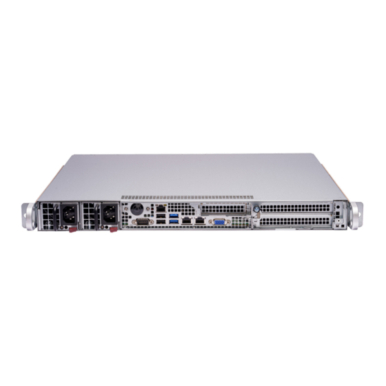
Chapter 1: Introduction 1.2 System Features The following views of the system display the main features. Refer to Appendix C for additional specifications. Front View Dedicated IPMI LAN Power Button with Status LED VGA Port USB Ports DC Power DC Power LAN2 Supply 1 Supply 2... - Page 11 Chapter 1: Introduction System Features: Front Feature Description Power Supplies Two redundant power supply modules: PWS1 on the right, PWS2 on the left. The main power switch applies or removes primary power from the power supply to Power Button with the server but maintains standby power.
-
Page 12: System Architecture
Chapter 1: Introduction 1.3 System Architecture This section covers the locations of the system electrical components and block diagrams of the motherboard and the overall system. USB 3.2 Gen 1 Ports PCIe Exapnsion Slots Power Supplies 4th Generation Intel® Xeon® Scalable Processor DIMM Slots Fans... -
Page 13: Motherboard Layout
Chapter 1: Introduction 1.4 Motherboard Layout Below is a layout of the X13SEW-TF motherboard with jumper, connector and LED locations shown. See the table on the following page for descriptions. For detailed descriptions, pinout information and jumper settings, refer to Chapter 4 or the Motherboard Manual. -
Page 14: Quick Reference Table
Chapter 1: Introduction Quick Reference Table Jumper Description Default Setting JBR1 BIOS Recovery Pins 1–2 (Normal) JBT1 CMOS Clear Open (Normal) JPL1 I210 LAN1 Enable/Disable Pins 1–2 (Enabled) JPL2 I210 LAN2 Enable/Disable Pins 1–2 (Enabled) JPL3 X550 LAN1 and LAN2 Enable/Disable Pins 1–2 (Enabled) JPME1 ME Recovery... - Page 15 Description SATA8–SATA9 SATA 3.0 Ports with SuperDOM Power SXB1A, SXB1B, SXB1C PCIe 5.0 x16 + x16 Supermicro Proprietary WIO Left Add-on Card Slots SXB2 PCIe 5.0 x8 (In x16) Supermicro Proprietary WIO Right Add-on Card Slot SGPIO2 Serial Link General Purpose I/O Header USB0/1 Back Panel USB 2.0 Ports...
-
Page 16: Motherboard Block Diagram
Chapter 1: Introduction Motherboard Block Diagram VR14 8 PHASE CPU1 DDR5 PECI:30 DDR5 SOCKET ID:0 4800 #1/#2 DMI3 SXB2 (WIO-R) PCIe GEN5 X8 PCIe X8 G5 PE0[7:0] JNVME2 PCIe GEN5 X8 MCIO x8 / 2x NVMe PCIe GEN5 X8 MCIO PCIe X8 G5 PE0[15:8] JNVME1 PCIe GEN5 X8... -
Page 17: Chapter 2 Server Installation
Chapter 2: Server Installation Chapter 2 Server Installation 2.1 Overview This chapter provides advice and instructions for mounting your system in a server rack. If your system is not already fully integrated with processors, system memory etc., refer to Chapter 3 for details on installing those specific components. -
Page 18: Rack Precautions
Chapter 2: Server Installation • This product is not suitable for use with visual display workplace devices according to §2 of the German Ordinance for Work with Visual Display Units. The ports of this equipment are suitable for connection to intra-building or unexposed wiring or cabling only. -
Page 19: Rack Mounting Considerations
Chapter 2: Server Installation • When not servicing, always keep the front door of the rack and all covers/panels on the servers closed to maintain proper cooling. • The AC power input ports are intended for installation in NEBS environments where rapid changes in line voltage may occur. - Page 20 Chapter 2: Server Installation To prevent bodily injury when mounting or servicing this unit in a rack, you must take special precautions to ensure that the system remains stable. The following guidelines are provided to ensure your safety: • This unit should be mounted at the bottom of the rack if it is the only unit in the rack. •...
-
Page 21: Installing The Rails
Chapter 2: Server Installation 2.4 Installing the Rails There are a variety of rack units on the market, which may require a slightly different assembly procedure. This rail set fits a rack between 25.6" and 33" deep. The following is a basic guideline for installing the system into a rack with the rack mounting hardware provided. -
Page 22: Installing The Outer Rails Onto The Rack
Chapter 2: Server Installation Installing the Outer Rails onto the Rack Each end of the assembled outer rail includes a bracket with square pegs to fit into your rack holes. If you have an older rack with round holes, these brackets must be removed, and you must use screws to secure the rail to the rack. -
Page 23: Installing The Chassis Into A Rack
Chapter 2: Server Installation 2.5 Installing the Chassis into a Rack Once rails are attached to the chassis and the rack, the chassis is ready to be installed into a rack. Installing the Chassis into a Rack 1. Confirm that inner and outer rails have been properly installed. 2. -
Page 24: Removing The Chassis From The Rack
Chapter 2: Server Installation Removing the Chassis from the Rack Caution! It is dangerous for a single person to off-load the heavy chassis from the rack without assistance. Be sure to have sufficient assistance supporting the chassis when removing it from the rack. -
Page 25: Installing The Chassis Into A Telco Rack
Chapter 2: Server Installation Installing the Chassis into a Telco Rack Follow the procedure below to install the chassis into a Telco (open type) rack. Installing the Chassis into a Telco Rack 1. Use the two L-shaped brackets (four total) to suspend the sides of the chassis within the rack. -
Page 26: Connecting Power And Ground In A Nebs Environment
Safety Ground, indicated by “Earth GND Symbol”. (Optional because Chassis GND stud is connected) • +Return, positive terminal (Battery Return, BR). Supermicro provides a cable for connection to the DC power supply. You should use the provided cable or an equivalent cable with the following specifications: • Positronic CBD connector. -
Page 27: Chassis Ground Stud Connections For Ac And Dc Systems
Chapter 2: Server Installation Note: The SYS-111E-FDWTR is DC-I and can be grounded in both CBN and IBN networks. It is suitable for installation in Network Telecommunication Facilities and in locations where the NEC applies. Connection of the +Return (BR) supports both North America, Isolated GP (single point connection to CBN) and Europe, Integrated GP (Multiple point connection to CBN) configurations. -
Page 28: Chapter 3 Maintenance And Component Installation
Chapter 3: Maintenance and Component Installation Chapter 3 Maintenance and Component Installation This chapter provides instructions on installing and replacing main system components. To prevent compatibility issues, only use components that match the specifications and/or part numbers given. Installation or replacement of most components require that power first be removed from the system. -
Page 29: Accessing The System
Chapter 3: Maintenance and Component Installation 3.2 Accessing the System The CSE-515B-R801W/R601W chassis features a removable top cover, which allows easy access to the inside of the chassis. Removing the Top Cover 1. Remove one screw and loosen the thumbscrew that holds the top cover in place. 2. -
Page 30: Processor And Heatsink Installation
• Thermal grease is pre-applied on a new heatsink. No additional thermal grease is needed. • Refer to the Supermicro website for updates on processor and memory support. • The CPU carriers XCC (SKT-1333L-0000-FXC) and MCC (SKT-1424L-001B-FXC) are shipped with the motherboard. -
Page 31: Installation Overview
Chapter 3: Maintenance and Component Installation Installation Overview After preparing the system and following ESD precautions, there are four steps to installing the processor and heatsink onto the motherboard. 1. Attach the processor to a plastic carrier to create the processor carrier assembly. 2. -
Page 32: Create The Processor Carrier Assembly
Chapter 3: Maintenance and Component Installation Create the Processor Carrier Assembly Process Carrier Assembly 1. Hold the processor with the gold pins (LGA lands) facing down. Locate the gold triangle at the corner of the processor and the corresponding hollowed triangle on the processor carrier as shown below. - Page 33 Chapter 3: Maintenance and Component Installation 2. Turn the processor over (with the gold pins up). Locate the CPU keys on the processor and the four latches on the carrier as shown below. SP XCC Latch CPU Key Latch CPU Key Latch Latch SP MCC...
- Page 34 Chapter 3: Maintenance and Component Installation 3. Locate the lever on the CPU socket and press it down as shown below. Lever Lever Carrier E1B Carrier E1A 4. Using Pin 1 as a guide, carefully align the CPU keys (A and B) on the processor against the CPU keys on the carrier (a and b) as shown in the drawing below.
- Page 35 Chapter 3: Maintenance and Component Installation 6. After the processor is placed inside the carrier, examine the four sides of the processor, making sure that the processor is properly seated on the carrier. SP XCC (Top View) (Component View) CPU Carrier Assembly SP MCC (Component View) (Top View)
-
Page 36: Creating The Phm
Chapter 3: Maintenance and Component Installation Creating the PHM After creating the processor carrier assembly, please follow the instructions below to mount the processor carrier into the heatsink to form the PHM. Note: If this is a new heatsink, the thermal grease has been pre-applied on the un- derside. - Page 37 Chapter 3: Maintenance and Component Installation CPU Carrier Assembly (CPU Component Side and Heatsink Bottom Side) SP MCC SP XCC Pin 1 Pin 1 Processor Heatsink Module (PHM)
-
Page 38: Preparing The Cpu Socket For Installation
Chapter 3: Maintenance and Component Installation Preparing the CPU Socket for Installation This motherboard comes with a plastic protective cover installed on the CPU socket. Remove it from the socket by following the instructions below: 1. Press the tabs inward. 2. -
Page 39: Installing The Phm Into The Cpu Socket
Chapter 3: Maintenance and Component Installation Installing the PHM into the CPU Socket 1. Locate four threaded fasteners (a, b, c, d) on the CPU socket. 2. Align PEEK nut A, which is next to the triangle (Pin 1) on the heatsink, against threaded fastener a on the CPU socket. -
Page 40: Removing The Phm From The Cpu Socket
Chapter 3: Maintenance and Component Installation Removing the PHM from the CPU Socket Before removing the PHM from the motherboard, be sure to shut down the system and unplug the power cables from the power supply. Then follow the steps below: 1. -
Page 41: Removing The Processor Carrier Assembly From The Phm
Chapter 3: Maintenance and Component Installation Removing the Processor Carrier Assembly from the PHM To remove the processor carrier assembly from the PHM, please follow the steps below: 1. Detach the four plastic clips (marked a, b, c, d) on the processor carrier assembly from the four corners of the heatsink (marked A, B, C, D) as shown in the drawings below. -
Page 42: Removing The Processor From The Processor Carrier Assembly
Chapter 3: Maintenance and Component Installation Removing the Processor from the Processor Carrier Assembly Once you have removed the processor carrier assembly from the PHM, you are ready to remove the processor from the processor carrier by following the steps below. 1. -
Page 43: Memory
Chapter 3: Maintenance and Component Installation 3.4 Memory Memory Support The X13SEW-TF supports up to 2048GB of ECC RDIMM/RDIMM 3DS DDR5 memory with speeds of up to 4800MT/s in eight memory slots. Refer to the tables below for the recommended DIMM population order and additional memory information. DDR5 Memory Table for 4th Gen Intel®... -
Page 44: General Guidelines For Optimizing Memory Performance
Chapter 3: Maintenance and Component Installation General Guidelines for Optimizing Memory Performance • It is recommended to use DDR5 memory of the same type, size, and speed. • Mixed DIMM speeds can be installed. However, all DIMMs will run at the speed of the slowest DIMM. -
Page 45: Dimm Installation
Chapter 3: Maintenance and Component Installation DIMM Installation JUIDB1 COM1 USB3/4 (3.2 Gen 1) LAN2 LAN1 IPMI_LAN 1. Insert the desired number of DIMMs USB0/1 JNCSI1 JPFR2 JTPM X550 into the memory slots based on the MH17 M.2 NVME JBT1 M.2-P recommended DIMM population table. -
Page 46: Motherboard Battery
Chapter 3: Maintenance and Component Installation 3.5 Motherboard Battery The motherboard uses non-volatile memory to retain system information when system power is removed. This memory is powered by a lithium battery residing on the motherboard. Replacing the Battery Begin by removing power from the system. -
Page 47: Storage Drives
These carriers also help promote proper airflow. Note: Enterprise level hard disk drives are recommended for use in Supermicro chassis and servers. For information on recommended HDDs, visit the Supermicro website at http://www. - Page 48 Chapter 3: Maintenance and Component Installation 3. Remove the drive brackets from the chassis. Insert the drive into the drive brackets and secure the drive to the bracket with screws, as shown below. 4. Secure the drive bracket to the chassis floor using four screws, as shown below. 5.
-
Page 49: Checking The Temperature Of An Nvme Drive
Chapter 3: Maintenance and Component Installation Checking the Temperature of an NVMe Drive There are two ways to check using the BMC Dashboard. Checking a Drive • BMC Dashboard > Server Health > NVMe SSD – Shows the temperatures of all NVMe drives. -
Page 50: System Cooling
Chapter 3: Maintenance and Component Installation 3.7 System Cooling The CSE-515B-R801W/R601W comes standard with six counter-rotating fans. Two additional fans may be added as an option. The fans can adjust their speed according to the heat level sensed in the system, which results in more efficient and quieter operation. -
Page 51: Replacing Fans
Chapter 3: Maintenance and Component Installation Replacing Fans If a fan fails, the remaining fans will ramp up to full speed, the overheat/fan fail LED on the control panel will blink on and off, and an alarm will sound. Replace any failed fan at your earliest convenience with the same type and model. -
Page 52: Air Shrouds
Chapter 3: Maintenance and Component Installation Air Shrouds The SYS-111E-FWTR/FDWTR support two air shrouds, one to direct airflow to the CPU and another to direct airflow to the PCIe cards. There are two types of PCIe card air shrouds, one for full-height cards and one for half-height cards. Replacing the Air Shroud 1. -
Page 53: Checking The Server Air Flow
Chapter 3: Maintenance and Component Installation Checking the Server Air Flow • Make sure there are no objects to obstruct airflow in and out of the server. • Use only recommended server parts. • Make sure no wires or foreign objects obstruct air flow through the chassis. Pull all excess cabling out of the airflow path or use shorter cables. -
Page 54: Power Supply
100V to 240V input range. The 600W DC power supplies can operate at a -44Vdc to -65Vdc input range. If replacing a power supply, the system does not need to be powered down. New units can be ordered directly from Supermicro or authorized distributors Replacing a Power Supply (SYS-111E-FWTR) 1. - Page 55 Chapter 3: Maintenance and Component Installation Replacing the Power Supply (SYS-111E-FDWTR) 1. Use the system's remote management to find the failed power supply. 2. Check the power supply's LED. Power Supply LED States LED Color Definition No power input Amber Power supply is off or failed Power supply is on and Green...
-
Page 56: Chapter 4 Motherboard Connections
Chapter 4: Motherboard Connections Chapter 4 Motherboard Connections This section describes the connections on the motherboard and provides pinout definitions. Note that depending on how the system is configured, not all connections are required. The LEDs on the motherboard are also described here. A motherboard layout indicating component locations may be found in Chapter 1. -
Page 57: Headers And Connectors
Chapter 4: Motherboard Connections 4.2 Headers and Connectors Chassis Intrusion A Chassis Intrusion header is located at JL1 on the motherboard. Attach the appropriate cable from the chassis to inform you of a chassis intrusion when the chassis is opened. Refer to the table below for pin definitions. - Page 58 In addition, this motherboard has two SATA 3.0 ports (SATA8, SATA9) that can be used with Supermicro SuperDOM's SATA DOM connectors with power pins bulit in, and do not require external power cables. Supermicro SuperDOMs are backward compatible with regular SATA...
- Page 59 Port 80 connection. Use this header to enhance system performance and data security. Refer to the table below for pin definitions. Go to the following link for more information on the TPM: http://www.supermicro.com/manuals/other/TPM.pdf. Trusted Platform Module Header (JTPM) Pin Definitions...
-
Page 60: Control Panel
These connectors are designed specifically for use with Supermicro chassis. See the figure below for the descriptions of the front control panel buttons and LED indicators. - Page 61 Chapter 4: Motherboard Connections Power Button The Power Button connection is located on pins 1 and 2 of JF1. Momentarily contacting both pins will power on/off the system. This button can also be configured to function as a suspend button (with a setting in the BIOS). To turn off the power when the system is in suspend mode, press the button for 4 seconds or longer.
- Page 62 Chapter 4: Motherboard Connections HDD LED The HDD LED connection is located on pins 13 and 14 of JF1. Attach a cable to pin 14 to show hard drive activity status. Refer to the table below for pin definitions. HDD LED Pin Definitions (JF1) Pins Definition...
-
Page 63: Input/Output Ports
Chapter 4: Motherboard Connections 4.3 Input/Output Ports Rear I/O Ports See the figure below for the locations and descriptions of the I/O ports on the rear of the motherboard. JUIDB1 COM1 USB3/4 (3.2 Gen 1) LAN2 LAN1 IPMI_LAN USB0/1 JNCSI1 JPFR2 JTPM X550... - Page 64 Chapter 4: Motherboard Connections COM Port There is one COM connection on this motherboard. COM1 is located next to the dedicated IPMI_LAN. COM Port Pin Definitions Pin# Definition Pin# Definition Ground LAN Ports The motherboard has two 10GbE LAN port located on the I/O panel. The two 10GbE LAN ports accept RJ45 cables.
- Page 65 Chapter 4: Motherboard Connections Unit Identifier Switch (UID-SW): One button with two functions A Unit Identifier (UID) switch and two LED Indicators are located on the motherboard. The UID switch is located next to the VGA port on the back panel. Function User Input Behavior...
-
Page 66: Jumpers
Chapter 4: Motherboard Connections 4.4 Jumpers Explanation of Jumpers Connector Pins To modify the operation of the motherboard, jumpers are used to choose between optional settings. Jumpers create shorts between two pins to change the function associated with it. Pin 1 Jumper is identified with a square solder pad on the printed circuit board. - Page 67 Chapter 4: Motherboard Connections BIOS Recovery Close pins 2-3 of jumper JBR1 for BIOS recovery. The default setting is on pins 1 and 2 for normal operation. Refer to the table below for jumper settings. The default setting is Normal. BIOS Recovery Jumper Settings Jumper Setting...
-
Page 68: Led Indicators
Chapter 4: Motherboard Connections 4.5 LED Indicators BMC Heartbeat LED LEDBMC is the BMC Heartbeat LED. When the LED is blinking green, BMC is working. Refer to the table below for the LED status. BMC Heartbeat LED LED Color Definition Green: Blinking BMC Normal M.2 LED... -
Page 69: Chapter 5 Software
The Supermicro website contains drivers and utilities for your system at https://www. supermicro.com/wdl/driver. Some of these must be installed, such as the chipset driver. After accessing the website, go into the CDR_Images (in the parent directory of the above link) and locate the ISO file for your motherboard. Download this file to a USB flash or media drive. -
Page 70: Superdoctor ® 5
5.2 SuperDoctor ® The Supermicro SuperDoctor 5 is a program that functions in a command-line or web-based interface for Windows and Linux operating systems. The program monitors such system health information as CPU temperature, system voltages, system power consumption, fan speed, and provides alerts via email or Simple Network Management Protocol (SNMP). -
Page 71: Bmc
There are several BIOS settings that are related to BMC. For general documentation and information on BMC, visit our website at: https://www.supermicro.com/en/solutions/management-software/bmc-resources BMC ADMIN User Password For security, each system is assigned a unique default BMC password for the ADMIN user. -
Page 72: Chapter 6 Optional Components
Module (TPM). A TPM is a security device that supports encryption and authentication in hard drives. It enables the motherboard to deny access if the TPM associated with the hard drive is not installed in the system. Details and installation procedures are at: http://www.supermicro.com/manuals/other/TPM.pdf... -
Page 73: Chapter 7 Troubleshooting And Support
Chapter 7 Troubleshooting and Support 7.1 Information Resources Website A great deal of information is available on the Supermicro website, supermicro.com. Products Figure 7-1. Supermicro Website • Specifications for servers and other hardware are available by clicking the menu icon, then selecting the Products option. -
Page 74: Bmc Interface
Security Center for recent security notices Supermicro Phone and Addresses 7.2 BMC Interface The system supports a Baseboard Management Controller (BMC) interface. It provides remote access, monitoring and management. There are several BIOS settings related to the BMC. -
Page 75: Troubleshooting Procedures
Chapter 6: Troubleshooting and Support 7.3 Troubleshooting Procedures Use the following procedures to troubleshoot your system. If you have followed all of the procedures below and still need assistance, refer to the Technical Support Procedures Returning Merchandise for Service section(s) in this chapter. Power down the system before changing any non hot-swap hardware components. -
Page 76: No Video
• Memory: Make sure that the memory modules are supported. Refer to the product page on our website at www.supermicro.com. Test the modules using memtest86 or a similar utility. • Storage drives: Make sure that all drives work properly. Replace if necessary. - Page 77 Also check the Control panel Overheat LED. • Adequate power supply: Make sure that the power supply provides adequate power to the system. Make sure that all power connectors are connected. Refer to the Supermicro website for the minimum power requirements. •...
-
Page 78: Crash Dump Using The Bmc Dashboard
In the event of a processor internal error (IERR) that crashes your system, you may want to provide information to support staff. You can download a crash dump of status information using the BMC Dashboard. The BMC manual is available at https://www.supermicro.com/ manuals/other/BMC_Users_Guide_X13.pdf. Check Error Log 1. -
Page 79: Cmos Clear
Chapter 6: Troubleshooting and Support 7.5 CMOS Clear JBT1 is used to clear CMOS, which will also clear any passwords. Instead of pins, this jumper consists of contact pads to prevent accidentally clearing the contents of CMOS. To Clear CMOS 1. -
Page 80: Where To Get Replacement Components
7.6 Where to Get Replacement Components If you need replacement parts for your system, to ensure the highest level of professional service and technical support, purchase exclusively from our Supermicro Authorized Distributors/System Integrators/Resellers. A list can be found at: http://www.supermicro.com. -
Page 81: Vendor Support Filing System
For issues related to Red Hat Enterprise Linux, since it is a subscription based OS, contact your account representative. 7.8 Feedback Supermicro values your feedback as we strive to improve our customer experience in all facets of our business. To provide feedback on our manuals, please email us at techwriterteam@... -
Page 82: Contacting Supermicro
San Jose, CA 95131 U.S.A. Tel: +1 (408) 503-8000 Fax: +1 (408) 503-8008 Email: marketing@supermicro.com (General Information) Sales-USA@supermicro.com (Sales Inquiries) Government_Sales-USA@supermicro.com (Gov. Sales Inquiries) support@supermicro.com (Technical Support) RMA@supermicro.com (RMA Support) Webmaster@supermicro.com (Webmaster) Website: www.supermicro.com Europe Address: Super Micro Computer B.V. - Page 83 Supermicro's Technical Support department for assistance. Only certified technicians should attempt to install or configure components. Read this appendix in its entirety before installing or configuring components in the Supermicro chassis. These warnings may also be found on our website at http://www.supermicro.com/about/...
- Page 84 Appendix A: Warning Statements Warnung WICHTIGE SICHERHEITSHINWEISE Dieses Warnsymbol bedeutet Gefahr. Sie befinden sich in einer Situation, die zu Verletzungen führen kann. Machen Sie sich vor der Arbeit mit Geräten mit den Gefahren elektrischer Schaltungen und den üblichen Verfahren zur Vorbeugung vor Unfällen vertraut. Suchen Sie mit der am Ende jeder Warnung angegebenen Anweisungsnummer nach der jeweiligen Übersetzung in den übersetzten Sicherheitshinweisen, die zusammen mit diesem Gerät ausgeliefert wurden.
- Page 85 Appendix A: Warning Statements . ٌ ا ك ً ف حالة و ٌ يك أى تتسبب ف اصابة جسذ ة ٌ هذا الزهز ع ٌ خطز !تحذ ز قبل أى تعول عىل أي هعذات،يك عىل علن بالوخاطز ال ا ٌجوة عي الذوائز ٍ...
- Page 86 Appendix A: Warning Statements Warnung Vor dem Anschließen des Systems an die Stromquelle die Installationsanweisungen lesen. ¡Advertencia! Lea las instrucciones de instalación antes de conectar el sistema a la red de alimentación. Attention Avant de brancher le système sur la source d'alimentation, consulter les directives d'installation. .יש...
- Page 87 Appendix A: Warning Statements Warnung Dieses Produkt ist darauf angewiesen, dass im Gebäude ein Kurzschluss- bzw. Überstromschutz installiert ist. Stellen Sie sicher, dass der Nennwert der Schutzvorrichtung nicht mehr als: 250 V, 20 A beträgt. ¡Advertencia! Este equipo utiliza el sistema de protección contra cortocircuitos (o sobrecorrientes) del edificio.
- Page 88 Appendix A: Warning Statements 電源切断の警告 システムコンポーネントの取り付けまたは取り外しのために、 シャーシー内部にアクセスするには、 システムの電源はすべてのソースから切断され、 電源コードは電源モジュールから取り外す必要が あります。 警告 在你打开机箱并安装或移除内部器件前,必须将系统完全断电,并移除电源线。 警告 在您打開機殼安裝或移除內部元件前,必須將系統完全斷電,並移除電源線。 Warnung Das System muss von allen Quellen der Energie und vom Netzanschlusskabel getrennt sein, das von den Spg.Versorgungsteilmodulen entfernt wird, bevor es auf den Chassisinnenraum zurückgreift, um Systemsbestandteile anzubringen oder zu entfernen. ¡Advertencia! El sistema debe ser disconnected de todas las fuentes de energía y del cable eléctrico quitado de los módulos de fuente de alimentación antes de tener acceso el interior del chasis para...
- Page 89 Appendix A: Warning Statements يجب فصم اننظاو من جميع مصادر انطاقت وإ ز انت سهك انكهرباء من وحدة امداد انطاقت قبم انىصىل إىن امنناطق انداخهيت نههيكم نتثبيج أو إ ز انت مكىناث الجهاز 경고! 시스템에 부품들을 장착하거나 제거하기 위해서는 섀시 내부에 접근하기 전에 반드시 전원 공급장치로부터...
- Page 90 Appendix A: Warning Statements Attention Il est vivement recommandé de confier l'installation, le remplacement et la maintenance de ces équipements à des personnels qualifiés et expérimentés. !אזהרה .צוות מוסמך בלבד רשאי להתקין, להחליף את הציוד או לתת שירות עבור הציוד واملدربيه...
- Page 91 Appendix A: Warning Statements Warnung Diese Einheit ist zur Installation in Bereichen mit beschränktem Zutritt vorgesehen. Der Zutritt zu derartigen Bereichen ist nur mit einem Spezialwerkzeug, Schloss und Schlüssel oder einer sonstigen Sicherheitsvorkehrung möglich. ¡Advertencia! Esta unidad ha sido diseñada para instalación en áreas de acceso restringido. Sólo puede obtenerse acceso a una de estas áreas mediante la utilización de una herramienta especial, cerradura con llave u otro medio de seguridad.
- Page 92 Appendix A: Warning Statements Battery Handling Warning! There is the danger of explosion if the battery is replaced incorrectly. Replace the battery only with the same or equivalent type recommended by the manufacturer. Dispose of used batteries according to the manufacturer's instructions 電池の取り扱い...
- Page 93 Appendix A: Warning Statements هناك خطر من انفجار يف حالة اسحبذال البطارية بطريقة غري صحيحة فعليل اسحبذال البطارية فقط بنفس النىع أو ما يعادلها مام أوصث به الرشمة املصنعة جخلص من البطاريات املسحعملة وفقا لحعليامت الرشمة الصانعة 경고! 배터리가 올바르게 교체되지 않으면 폭발의 위험이 있습니다. 기존 배터리와 동일하거나 제 조사에서...
- Page 94 Appendix A: Warning Statements ¡Advertencia! Puede que esta unidad tenga más de una conexión para fuentes de alimentación. Para cortar por completo el suministro de energía, deben desconectarse todas las conexiones. Attention Cette unité peut avoir plus d'une connexion d'alimentation. Pour supprimer toute tension et tout courant électrique de l'unité, toutes les connexions d'alimentation doivent être débranchées.
- Page 95 Appendix A: Warning Statements Backplane Voltage Warning! Hazardous voltage or energy is present on the backplane when the system is operating. Use caution when servicing. バックプレーンの電圧 システムの稼働中は危険な電圧または電力が、 バックプレーン上にかかっています。 修理する際には注意く ださい。 警告 当系统正在进行时,背板上有很危险的电压或能量,进行维修时务必小心。 警告 當系統正在進行時,背板上有危險的電壓或能量,進行維修時務必小心。 Warnung Wenn das System in Betrieb ist, treten auf der Rückwandplatine gefährliche Spannungen oder Energien auf.
- Page 96 Appendix A: Warning Statements هناك خطز مه التيار الكهزبايئ أوالطاقة املىجىدة عىل اللىحة عندما يكىن النظام يعمل كه حذ ر ا عند خدمة هذا الجهاس 경고! 시스템이 동작 중일 때 후면판 (Backplane)에는 위험한 전압이나 에너지가 발생 합니다. 서비스 작업 시 주의하십시오. Waarschuwing Een gevaarlijke spanning of energie is aanwezig op de backplane wanneer het systeem in gebruik is.
- Page 97 Appendix A: Warning Statements תיאום חוקי החשמל הארצי !אזהרה .התקנת הציוד חייבת להיות תואמת לחוקי החשמל המקומיים והארציים تركيب املعدات الكهربائية يجب أن ميتثل للقىاويه املحلية والىطىية املتعلقة بالكهرباء 경고! 현 지역 및 국가의 전기 규정에 따라 장비를 설치해야 합니다. Waarschuwing Bij installatie van de apparatuur moet worden voldaan aan de lokale en nationale elektriciteitsvoorschriften.
- Page 98 Appendix A: Warning Statements Attention La mise au rebut ou le recyclage de ce produit sont généralement soumis à des lois et/ou directives de respect de l'environnement. Renseignez-vous auprès de l'organisme compétent. סילוק המוצר !אזהרה .סילוק סופי של מוצר זה חייב להיות בהתאם להנחיות וחוקי המדינה التخلص...
- Page 99 Appendix A: Warning Statements Warnung Gefährlich Bewegende Teile. Von den bewegenden Lüfterblätter fern halten. Die Lüfter drehen sich u. U. noch, wenn die Lüfterbaugruppe aus dem Chassis genommen wird. Halten Sie Finger, Schraubendreher und andere Gegenstände von den Öffnungen des Lüftergehäuses entfernt.
- Page 100 Verbindungskabeln, Stromkabeln und/oder Adapater, die Ihre örtlichen Sicherheitsstandards einhalten. Der Gebrauch von anderen Kabeln und Adapter können Fehlfunktionen oder Feuer verursachen. Die Richtlinien untersagen das Nutzen von UL oder CAS zertifizierten Kabeln (mit UL/CSA gekennzeichnet), an Geräten oder Produkten die nicht mit Supermicro gekennzeichnet sind.
- Page 101 .قيرح وأ لطع يف ببستي دق ىرخأ تالوحمو تالباك يأ مادختسا .ميلسلا سباقلاو لصوملا مجح لبق نم ةدمتعملا تالباكلا مادختسا تادعملاو ةيئابرهكلا ةزهجألل ةمالسلا نوناق رظحيUL وأCSA ( ةمالع لمحت يتلاوUL/CSA) لبق نم ةددحملاو ةينعملا تاجتنملا ريغ ىرخأ تادعم يأ عمSupermicro.
- Page 102 사항을 준수하여 제공되거나 지정된 연결 혹은 구매 케이블, 전원 케이블 및 AC 어댑터를 사용하십시오. 다른 케이블이나 어댑터를 사용하면 오작동이나 화재가 발생할 수 있습니다. 전기 용품 안전법은 UL 또는 CSA 인증 케이블 (코드에 UL / CSA가 표시된 케이블)을 Supermicro 가 지정한 제품 이외의 전기 장치에 사용하는 것을 금지합니다. Stroomkabel en AC-Adapter...
- Page 103 Supermicro's Technical Support department for assistance. Only certified technicians should attempt to install or configure components. Read this appendix in its entirety before installing or configuring components in the Supermicro chassis. These warnings may also be found on our website at http://www.supermicro.com/about/...
- Page 104 Appendix B: Standardized Warning Statements Warnung WICHTIGE SICHERHEITSHINWEISE Dieses Warnsymbol bedeutet Gefahr. Sie befinden sich in einer Situation, die zu Verletzungen führen kann. Machen Sie sich vor der Arbeit mit Geräten mit den Gefahren elektrischer Schaltungen und den üblichen Verfahren zur Vorbeugung vor Unfällen vertraut. Suchen Sie mit der am Ende jeder Warnung angegebenen Anweisungsnummer nach der jeweiligen Übersetzung in den übersetzten Sicherheitshinweisen, die zusammen mit diesem Gerät ausgeliefert wurden.
- Page 105 Appendix B: Standardized Warning Statements תקנון הצהרות אזהרה הצהרות הבאות הן אזהרות על פי תקני התעשייה, על מנת להזהיר את המשתמש מפני חבלה פיזית אפשרית. במידה ויש שאלות או היתקלות בבעיה כלשהי, יש ליצור קשר עם מחלקת תמיכה .טכנית של סופרמיקרו. טכנאים מוסמכים בלבד רשאים להתקין או להגדיר את הרכיבים .יש...
- Page 106 Appendix B: Standardized Warning Statements Installation Instructions Warning! Read the installation instructions before connecting the system to the power source. 設置手順書 システムを電源に接続する前に、 設置手順書をお読み下さい。 警告 将此系统连接电源前,请先阅读安装说明。 警告 將系統與電源連接前,請先閱讀安裝說明。 Warnung Vor dem Anschließen des Systems an die Stromquelle die Installationsanweisungen lesen. ¡Advertencia! Lea las instrucciones de instalación antes de conectar el sistema a la red de alimentación.
- Page 107 Appendix B: Standardized Warning Statements Circuit Breaker Warning! This product relies on the building's installation for short-circuit (overcurrent) protection. Ensure that the protective device is rated not greater than: 60VDC, 20A. サーキッ ト ・ ブレーカー この製品は、 短絡 (過電流) 保護装置がある建物での設置を前提としています。 保護装置の定格が60VDC、 20Aを超えないこ とを確認下さい。 警告...
- Page 108 Appendix B: Standardized Warning Statements מוצר זה מסתמך על הגנה המותקנת במבנים למניעת קצר חשמלי. יש לוודא כי 60VDC, 20A-המכשיר המגן מפני הקצר החשמלי הוא לא יותר מ هذا املنتج يعتمد عىل معداث الحاميت مه الدوائ ر القصرية التي تم تثبيتها يف املبنى...
- Page 109 Appendix B: Standardized Warning Statements Power Disconnection Warning Warning! The system must be disconnected from all sources of power and the power cord removed from the power supply module(s) before accessing the chassis interior to install or remove system components. 電源切断の警告...
- Page 110 Appendix B: Standardized Warning Statements Attention Le système doit être débranché de toutes les sources de puissance ainsi que de son cordon d'alimentation secteur avant d'accéder à l'intérieur du chassis pour installer ou enlever des composants de systéme. אזהרה מפני ניתוק חשמלי !אזהרה...
- Page 111 Appendix B: Standardized Warning Statements Equipment Installation Warning! Only trained and qualified personnel should be allowed to install, replace, or service this equipment. 機器の設置 トレーニングを受け認定された人だけがこの装置の設置、 交換、 またはサービスを許可されていま す。 警告 只有经过培训且具有资格的人员才能进行此设备的安装、更换和维修。 警告 只有經過受訓且具資格人員才可安裝、更換與維修此設備。 Warnung Das Installieren, Ersetzen oder Bedienen dieser Ausrüstung sollte nur geschultem, qualifiziertem Personal gestattet werden.
- Page 112 Appendix B: Standardized Warning Statements Restricted Area Warning! This unit is intended for installation in restricted access areas. A restricted access area can be accessed only through the use of a special tool, lock and key, or other means of security. (This warning does not apply to workstations). アクセス制限区域...
- Page 113 Appendix B: Standardized Warning Statements אזור עם גישה מוגבלת !אזהרה יש להתקין את היחידה באזורים שיש בהם הגבלת גישה. הגישה ניתנת בעזרת (.'כלי אבטחה בלבד (מפתח, מנעול וכד . تخصيص هذه انىحذة نترك ب ُ ها ف مناطق محظورة تم ،...
- Page 114 Appendix B: Standardized Warning Statements Battery Handling Warning! There is the danger of explosion if the battery is replaced incorrectly. Replace the battery only with the same or equivalent type recommended by the manufacturer. Dispose of used batteries according to the manufacturer's instructions 電池の取り扱い...
- Page 115 Appendix B: Standardized Warning Statements هناك خطر من انفجار يف حالة اسحبذال البطارية بطريقة غري صحيحة فعليل اسحبذال البطارية فقط بنفس النىع أو ما يعادلها مام أوصث به الرشمة املصنعة جخلص من البطاريات املسحعملة وفقا لحعليامت الرشمة الصانعة 경고! 배터리가 올바르게 교체되지 않으면 폭발의 위험이 있습니다. 기존 배터리와 동일하거나 제 조사에서...
- Page 116 Appendix B: Standardized Warning Statements Warnung Dieses Gerät kann mehr als eine Stromzufuhr haben. Um sicherzustellen, dass der Einheit kein trom zugeführt wird, müssen alle Verbindungen entfernt werden. ¡Advertencia! Puede que esta unidad tenga más de una conexión para fuentes de alimentación. Para cortar por completo el suministro de energía, deben desconectarse todas las conexiones.
- Page 117 Appendix B: Standardized Warning Statements Backplane Voltage Warning! Hazardous voltage or energy is present on the backplane when the system is operating. Use caution when servicing. バックプレーンの電圧 システムの稼働中は危険な電圧または電力が、 バックプレーン上にかかっています。 修理する際には注意く ださい。 警告 当系统正在进行时,背板上有很危险的电压或能量,进行维修时务必小心。 警告 當系統正在進行時,背板上有危險的電壓或能量,進行維修時務必小心。 Warnung Wenn das System in Betrieb ist, treten auf der Rückwandplatine gefährliche Spannungen oder Energien auf.
- Page 118 Appendix B: Standardized Warning Statements هناك خطز مه التيار الكهزبايئ أوالطاقة املىجىدة عىل اللىحة عندما يكىن النظام يعمل كه حذ ر ا عند خدمة هذا الجهاس 경고! 시스템이 동작 중일 때 후면판 (Backplane)에는 위험한 전압이나 에너지가 발생 합니다. 서비스 작업 시 주의하십시오. Waarschuwing Een gevaarlijke spanning of energie is aanwezig op de backplane wanneer het systeem in gebruik is.
- Page 119 Appendix B: Standardized Warning Statements תיאום חוקי החשמל הארצי !אזהרה .התקנת הציוד חייבת להיות תואמת לחוקי החשמל המקומיים והארציים تركيب املعدات الكهربائية يجب أن ميتثل للقىاويه املحلية والىطىية املتعلقة بالكهرباء 경고! 현 지역 및 국가의 전기 규정에 따라 장비를 설치해야 합니다. Waarschuwing Bij installatie van de apparatuur moet worden voldaan aan de lokale en nationale elektriciteitsvoorschriften.
- Page 120 Appendix B: Standardized Warning Statements Attention La mise au rebut ou le recyclage de ce produit sont généralement soumis à des lois et/ou directives de respect de l'environnement. Renseignez-vous auprès de l'organisme compétent. סילוק המוצר !אזהרה .סילוק סופי של מוצר זה חייב להיות בהתאם להנחיות וחוקי המדינה التخلص...
- Page 121 Appendix B: Standardized Warning Statements Warnung Gefährlich Bewegende Teile. Von den bewegenden Lüfterblätter fern halten. Die Lüfter drehen sich u. U. noch, wenn die Lüfterbaugruppe aus dem Chassis genommen wird. Halten Sie Finger, Schraubendreher und andere Gegenstände von den Öffnungen des Lüftergehäuses entfernt.
- Page 122 Appendix B: Standardized Warning Statements DC Power Supply Warning! When stranded wiring is required, use approved wiring terminations, such as closedloop or spade-type with upturned lugs. These terminations should be the appropriate size for the wires and should clamp both the insulation and conductor. 警告...
- Page 123 Appendix B: Standardized Warning Statements وأ ةقلغم ةقلح لثم ،اهيلع ةقفاوملا ءاهنإ كالسألا مادختساو ،لبسلا مهب تعطقت نيذلا كالسألا ابولطم نوكي امدنع بجيو كالسألل بسانملا مجحلا نوكي تاءاهنإلا هذهل يغبنيو .ةبولقم تاورعلا عم عونلا ةيقيقحلا اهئامسأب ءايشألا .لصومو لزعلا نم لك حبك 주의! 꼬인...
- Page 124 Appendix B: Standardized Warning Statements 警告 進行以下任一操作程序前,請確保直流電路已斷電。 警告 请在进行以下任一操作程序前,确保直流电路的电源已经断开。 Warnung Vor Ausführung der folgenden Vorgänge ist sicherzustellen, daß die Gleichstromschaltung keinen Strom erhält. ¡Advertencia! Antes de proceder con los siguientes pasos, comprobar que la alimentación del circuito de corriente continua (CC) esté cortada (OFF). Attention Avant de pratiquer l'une quelconque des procédures ci-dessous, vérifier que le circuit en courant continu n'est plus sous tension.
- Page 125 Appendix B: Standardized Warning Statements Hazardous Voltage or Energy Present on DC Power Terminals Warning! Hazardous voltage or energy may be present on DC power terminals. Always replace cover when terminals are not in service. Be sure uninsulated conductors are not accessible when cover is in place.
- Page 126 Appendix B: Standardized Warning Statements امدنع امئاد ءاطغ لادبتسا .ةمصاعلا ةقاطلا تاطحم ىلع ةدوجوم نوكت ةقاطلا وأ ةرطخلا دهجلا دق ءاطغلا امدنع اهيلإ لوصولا نكمي ال لوزعم ريغ تالصوملا هيف كش ال امم .ةمدخلا يف تسيل تاطحملا .هناكم يف 주의! DC전원...
- Page 127 Appendix C: System Specifications Appendix C System Specifications Processors Support single socket P+ (LGA-4677) for 4th Gen Intel® Xeon® Scalable processors and the thermal design power (TDP) up to 205W. Note: Refer to the motherboard specifications pages on our website for updates to supported processors. BIOS 256Mb SPI AMI®...
- Page 128 Appendix C: System Specifications Power Supply Model: PWS-601S-1R, 600W Redundant DC48V input w/PMBus power supply Total Output Power: 600W: (-44) - (-65) Vdc (Acceptable DC Input Voltage with ETSI standard: -40Vdc to -57Vdc) +12V: Max: 50A 5V SB: Max: 3A / Min: 0A Model: PWS-804S-1R, 800W AC Redundant Power Supplies with PMBus;...
- Page 129 Appendix C: System Specifications Applied Directives, Standards EMC/EMI: 2014/30/EU (EMC Directive) Electromagnetic Compatibility Regulations 2016 FCC Part 15 Subpart B ICES-003 VCCI-CISPR 32 AS/NZS CISPR 32 BS/EN 55032 BS/EN 55035 CISPR 32 CISPR 24/CISPR 35 BS/EN 61000-3-2 BS/EN 61000-3-3 BS/EN 61000-4-2 BS/EN 61000-4-3 BS/EN 61000-4-4 BS/EN 61000-4-5...
Need help?
Do you have a question about the SuperServer SYS-111E-FWTR and is the answer not in the manual?
Questions and answers