
Related Manuals for Axminster WORKSHOP AW150BDS


Summary of Contents for Axminster WORKSHOP AW150BDS
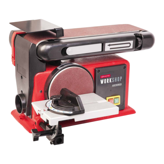
- Page 1 Code 107679 Original Instructions AW150BDS Belt & Disc Sander AT: 09/02/2022 BOOK VERSION: 03...
-
Page 2: Eu Declaration Of Conformity
Trouble Shooting Exploded Diagrams/Lists 20-21-22 Wiring Diagram EU DECLARATION OF CONFORMITY Cert No: MM491E EU Declaration of Conformity Axminster Tool Centre Ltd This machine complies with the following directives: Axminster Devon EX13 5PH UK axminstertools.com 2006/42/EC EN 55014-1: 2017+A11 2014/30/EU... -
Page 3: What's Included
WHAT’S INCLUDED Quantity Item Part Model Number AW150BDS Belt & Disc Sander Worktable Hex Key Mitre Fence Linisher Guard Instruction Manual NOTE: Please read the Instruction Manual prior to using your new machine; as well as the operating procedures for your new machine, there are numerous hints and tips to help you to use the machine safely and to maintain its efficiency and prolong its life. -
Page 4: General Instructions For 230V Machines
INTRODUCTION A neatly designed belt and disc sander. hexagon socket bolts to loosen with a key, suiting the task in hand. The belt has close fitting guarding which helps this The worktable on the belt and disc sander is a decent size machine achieve a high level of efficient dust extraction. -
Page 5: Specification
SPECIFIC SAFETY PRECAUTIONS FOR SANDING MACHINES DO NOT sand very small pieces of work with bare hands; Always offer the work piece to the belt/disc so that the try to construct some form of holder. motion carries the work against the restraining surface i.e. the work stop or the table (use the left hand side of the Make sure you are comfortable before you start work, disc). - Page 6 ASSEMBLY Using a square adjust the table until its perpendicular with the sanding disc. Loosen grub screw Machined hole Reset the pointer to ‘ZERO’ by loosening clamping screw. Machined face Remove the caphead screws & washers Slide the table (B) mounting bar into the machined hole and tighten the grub screw using the supplied Hex key.
- Page 7 ASSEMBLY/SETUP & ADJUSTMENT Pointer 1.6mm clearance required Slide the mitre fence (D) onto the table, place a square against the fence/disc and adjust until square. Reset the pointer to ‘Zero’ . Loosen caphead screw The gap between the table and the disc should be set to a maximum of 1.6mm to clear the debris and to ensure sufficient support for the timber.
-
Page 8: Setup And Adjustment
SETUP & ADJUSTMENT Tighten the two Hex screws to secure the linisher in position, see step 3. Transfer the work table (B) from the disc function mount- ing to the linisher’s mounting hole and secure in position. Setup the table as described earlier, see the following steps. - Page 9 SETUP & ADJUSTMENT Tracking the Linisher Belt The tracking control works as follows:- Using your hand, roll the belt towards the drive drum, check that the belt stays in the middle of the table, if not, adjust the track control slightly, and move the belt again, continue until the belt runs down the centre of the linisher’s table DO NOT make large adjustments, and remember the belt may take...
-
Page 10: Illustration And Parts Description
ILLUSTRATION AND PARTS DESCRIPTION Linisher guard Belt tensioning lever Linisher abrasive belt Belt tracking wheel Sanding disc NVR ON/OFF control switch Worktable Mitre fence 63mm dust extraction outlet Worktable tilt assembly Clamping star knob Worktable tilt scale (A) and pointer (B) Mitre fence pointer (A), scale (B) and clamping knob (C) - Page 11 ILLUSTRATION AND PARTS DESCRIPTION Linisher’s stop/ levelling bolt Drive belt cover Work bench mounting hole Mitre fence and Hex key storage holders Clamping Hex bolts, access holes for linisher assembly...
- Page 12 ILLUSTRATION AND PARTS DESCRIPTION NVR ON/OFF control switch 63mm dust extraction outlet Drive belt tensioning grub screw and locking nut Linisher guard/Workstop, can be used as a work support Worktable adjusting Hex bolt when the linisher is in the vertical position Three function positions Linisher function with worktable Linisher function, utilising the...
- Page 13 OPERATING INSTRUCTIONS/ CHANGING THE ABRASIVE BELT/DISC Sanding Disc DISCONNECT THE SANDER FROM MAKE SURE THE SANDER IS ON A THE MAINS SUPPLY BEFORE FLAT LEVEL SURFACE. CONTINUING! NOTE: GO ROUND AND MAKE SURE EVERYTHING IS SECURE, FASTENED DOWN, THAT ALL TOOLS ARE CLEARED AWAY FROM THE WORK AREA! WARNING!! KEEP TOOLS AND...
-
Page 14: Changing The Abrasive Belt/Disc
CHANGING THE ABRASIVE BELT/DISC Linisher Belt DISCONNECT THE SANDER FROM THE MAINS SUPPLY BEFORE CONTINUING! The abrasive disc is attached to the sander’s face by Velcro, a strip of fabric that clings when pressed together. Simply peel off the old abrasive disc. Clean the surface of the disc. Loosen the two clamping Hex screws holding the linisher and raise to the vertical position. - Page 15 CHANGING THE ABRASIVE BELT/DISC Loosen the two screws holding the rear guard. WEAR A DUST MASK & EYE PROTECTION WHEN CHANGING THE BELT! Remove the linisher belt. Inspect the new belt, ensure that there are no tears or rips especially along the edges, check Lift and remove the rear guard, place to one side.
- Page 16 CHANGING THE ABRASIVE BELT/DISC Remove the two screws holding the side extraction panel and check for signs of build up of dust and debris. Clean and replace the panel. Also clean the inside of the linisher. Slide the belt over the drums, making sure the arrows on the belt are pointing down towards the drive drum.
-
Page 17: Maintenance
MAINTENANCE DISCONNECT THE SANDER FROM THE MAINS SUPPLY BEFORE CONTINUING! WEAR A DUST MASK & EYE PROTECTION WHEN CLEANING YOUR SANDER! There is very little mechanical maintenance that can be carried out on the machine. Most prudent maintenance is preventative and concerned with keeping the machine clean. - Page 18 MAINTENANCE Grub screw Lock nut 1-2mm Depression Check the belt tension, if required adjust the drive belt tensioning grub screw and locking nut using the Hex key (C) and spanner, see image (4-5). Turn the grub screw clockwise (+) to push the motor down or anti-clockwise (-) to decrease the tension.
-
Page 19: Troubleshooting
TROUBLE SHOOTING PROBLEM POSSIBLE CAUSE REMEDY 1. Defective or broken “ON -OFF” switch 1-3. Replace all broken or defective parts before using the sander. Contact us on 03332 406406 2. Defective or damaged switch cord Motor will not run 3. Defective or damaged switch relay 4. - Page 20 EXPLODED DIAGRAMS/LISTS...
- Page 21 EXPLODED DIAGRAMS/LISTS Specification Joint lever Philips screw M5 x 35 Spring Belt guard Support Hex screw M8 x 35 Support cover Big flat washer M4 x 8 Philips screw M5 x 25 Screw M12 x 10 5 x 10 Tension knob Hex screw M12 x 30 Sleeve...
- Page 22 EXPLODED DIAGRAMS/LISTS Hex nut Dust hood φ40 Knob Wave washer Hex nut Mitre gauge knob Table pointer Mitre gauge pointer Table support rod Wire connection box cover Connect block Mitre gauge Belt Protect plate Motor arbor wheel Mitre gauge rod Hex bolt M6 x 122 Disc hook...
-
Page 23: Wiring Diagram
WIRING DIAGRAM... - Page 24 The packaging is suitable for recycling. Please dispose of it in a responsible manner. EU Countries Only Do not dispose of electric tools together with household waste material. By law they must be collected and recycled separately. Axminster Tools, Axminster Devon EX13 5PH axminstertools.com...
Need help?
Do you have a question about the WORKSHOP AW150BDS and is the answer not in the manual?
Questions and answers