
Related Manuals for Axminster AW18BDS


Summary of Contents for Axminster AW18BDS
- Page 1 Code 111998 Original Instructions AW18BDS Belt Disc Sander AT20/12/2024 BOOK VERSION: 1...
-
Page 2: Table Of Contents
Table of Contents TABLE OF CONTENTS Table of contents Safety guidelines Package contents Key parts diagram Assembly instructions Operating instructions Maintenance Troubleshooting Exploded view Part list Conformity Certificates SPECIFICATIONS Motor 230-240V/50Hz, 550W Speed (no load) 2980 RPM Belt size 25x1067mm Belt speed 14m/s Disc size... -
Page 3: Safety Guidelines - Definitions
Safety Guidelines SAFETY GUIDELINES - DEFINITIONS • Always wear safety goggles or safety glasses with side shields. • Always wear respiratory and hearing protection. • To reduce the risk of injury, user and all bystanders must read and understand instruction manual before using this product. •... -
Page 4: Power Tool Safety
Safety Guidelines POWER TOOL SAFETY 1. READ and become familiar with the entire Instruction Manual. LEARN the tool’s application, limitations and possible hazards. 2. KEEP GUARDS IN PLACE and in working order. 3. REMOVE ADJUSTING KEYS AND WRENCHES. Form the habit of checking to see that keys and adjusting wrenches are removed from the tool before turning ON. - Page 5 Safety Guidelines 17. USE RECOMMENDED ACCESSORIES. Consult this Instruction Manual for recommended accessories. The use of improper accessories may cause risk of injury to yourself or others. 18. NEVER STAND ON THE TOOL. Serious injury could occur if the tool is tipped or if the cutting tool is unintentionally contacted.
- Page 6 Safety Guidelines POWER TOOL SAFETY 1. USE sander on horizontal surfaces only. Operating the sander when mounted on non-horizontal surfaces might result in motor damage. 2. TO STOP it from tipping over or moving when in use, the sander must be securely fastened to a bench top or supporting surface.
-
Page 7: Grounding Instructions
Safety Guidelines IMPORTANT INFORMATION-Electrical GROUNDING INSTRUCTIONS All grounded, cord-connected machines: In the event of a malfunction or breakdown, grounding provides a path of least resistance for electric current to reduce the risk of electric shock. This machine is equipped with an electric cord having an equipment grounding conductor and a grounding plug. - Page 8 Safety Guidelines Use only 3-wire extension cords that have 3-pronged grounding type plugs and matching 3-conductor receptacles that accept the machine’s plug, as shown in Fig. A. Repair or replace damaged or worn cord immediately. WARNING! In all cases,make certain the receptacle in question is properly grounded. If you are not sure,have a electrician check the receptacle.
-
Page 9: Package Contents
Packaging Contents Package contents No. Description Qty. Belt / disc sander (not shown) Disc worktable Disc table handle Flat washer D8 Belt table handle Belt worktable Miter gauge assy Belt tension handle Inner hex wrench Sanding disc cover Philips screw... -
Page 10: Key Parts Diagram
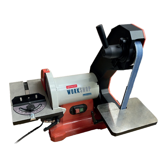
Key Parts Diagram No. Description 8 in. diameter sanding disc Miter gauge assy Disc worktable Base Disc table handle On / Off switch Belt table handle Belt worktable 1 in. width / 42 in. length sanding belt Belt tracking knob Belt tension handle... -
Page 11: Installing Tension Handle
properly. INSTALLING TENSION HANDLE Assembly Instructions Screw the tension handle (1) into the hole (2) of the hub and lock it. MOUNTING WORKTABLE ON DISC The larger worktable is used with the sanding disc. It should be used to support workpieces in all sanding operations except inside curve applications. -
Page 12: Assembly Instructions
Assembly Instructions MOUNTING WORKTABLE ON BELT 1. Attach the belt work table (1) to the sanding frame using a handle (2) and flat washer (3) as shown. NOTE: Ensure the locating pin (4) passes through the table bracket and the registration disc of the bracket is facing inwards. -
Page 13: Belt Platen
Operating Instructions CAUTION Always lock the switch off when the grinder is not in use. Remove the key and keep it in a safe place. In the event of a power failure, blown fuse, or tripped circuit breaker, turn the switch off and remove the key, preventing an accidental startup when the power comes on. - Page 14 Operating Instructions TO PROPERLY TRACK THE SANDING BELT 1. Plug in the sander. 2. Turn power switch ON, then immediately OFF, noting whether the belt (1) tends to down slide off its track, and to which side of the sander. 3.
-
Page 15: Replacing Sanding Disc
Maintenance WARNING! For your safety, turn switch OFF and remove the power cord from the electrical outlet before adjusting or performing maintenance on your sander. To avoid electric shock or fire, all repairs to the electrical components should be done by a qualified service technician. Before each use check for damaged, missing, or worn parts;... -
Page 16: Replacing Sanding Belt
Maintenance REPLACING SANDING BELT 1. Remove the belt cover (2) by loosen the inner hex nut (1). NOTE: No need remove the inner hex nut. 2. Release belt tension by pulling down on tension handle (2). Slide old belt off the drive and tracking wheels. -
Page 17: Troubleshooting Guide
Troubleshooting Guide WARNING! To avoid injury from an accidental start, turn the switch OFF and always remove the plug from the power source before making any adjustments. Not connected to power source. Connect to power source. Determine reason for blown fuse/ tripped breaker (such as short circuit Branch circuit fuse is blown or the or motor overload). -
Page 18: Exploded View
Exploded View... -
Page 19: Part List
Part List Descripiton Qty. Descripiton Qty. Belt tension knob Cord clip-6P4 Tension knob base Cord clip plate Hex screw M8×12 Cord bushing Belt tension spring External teeth lock washer D4 Circlip for shaft D16 Phillips screw with flat and spring washer M5×8 Driven eccentric shaft assembly Base Small knob... -
Page 20: Conformity Certificates
EN ISO 12100:2010, EN 62841-1:2015 Additional information: Name and address of person authorised to compile the technical file: Axminster Tool Centre Ltd, A-201, Haagsche Hof, Parkstraat 83, The Hague, 2514 JG, Netherlands The machinery fulfils all relevant provisions of Supply of Machinery (Safety) Regulations 2008 as amended. - Page 21 Product model: Axminster Workshop AW18BDS Belt and Disc Sander Name and address of the manufacturer: Axminster Tool Centre Ltd, Unit 10 Weycroft Avenue, Axminster, Devon EX13 5PH, United Kingdom This declaration of conformity is issued under the sole responsibility of the manufacturer.
- Page 24 The packaging is suitable for recycling. Please dispose of it in a responsible manner. EU Countries Only Do not dispose of electric tools together with household waste material. By law they must be collected and recycled separately. Axminster Tools, Axminster Devon EX13 5PH axminstertools.com...
Need help?
Do you have a question about the AW18BDS and is the answer not in the manual?
Questions and answers