
Related Manuals for Axminster AS408


Summary of Contents for Axminster AS408
- Page 1 AS408 Belt & Disc Sander A X M I N S T E R W H I T E Axminster Reference No: AS408 w w w. a x m i n s t e r. c o . u k...
-
Page 2: Table Of Contents
Index of Contents... Page No. Index of Contents........................01 Declaration of Conformity………….………..……..…………..........01 What’s in the Box………….………..……..…………..........02-03-04 General Instructions for 240v Machines.................. 05 Specific to Sanding Machines.................... 06-07 Specifications….………..……..…………................07 Assembly….………..……..…………............. 08-09-10-11-12-13-14 Assembly Configurations..................... 15-16 Illustration & Parts Description..................17-18-19 Sanding Configurations...................... -
Page 3: What's In The Box
What’s in the Box... A X M I N S T E R W H I T E Model Number: BDS-48Q 1 off: Belt & Disc Sander 1 off: Mitre Fence 1 off: Dust Extraction Moulding 1 off: Table Support Steel Rod 1 off: Table (Adjustable) 1 off:... - Page 4 What’s in the Box... A X M I N S T E R W H I T E www.axminster.co.uk...
- Page 5 What’s in the Box... A X M I N S T E R W H I T E Having opened the box, remove all the components stowed in the packaging. Place these carefully to one side. Remove the top packaging and lift the machine out of the box and place upon a clear flat surface, taking care not to trap or pinch the power cable under the chassis.
-
Page 6: General Instructions For 240V Machines
(P .S. don’t forget… don’t leave the spare belts/discs in the damp either). Keep the work area as uncluttered as is practical, this includes personnel as well as material. UNDER NO CIRCUMSTANCES SHOULD WARNING!! CHILDREN BE ALLOWED IN WORK AREAS www.axminster.co.uk... -
Page 7: Specific To Sanding Machines
Specific to Sanding Machines... A X M I N S T E R W H I T E WARNING! THE SANDING DISC CANNOT BE DECLUTCHED FROM THE BELT AND VICE VERSA, BOTH FUNCTIONS ARE ACTIVE WHEN THE MACHINE IS RUNNING. REMEMBER THIS, AND DO NOT LEAVE LOOSE OBJECTS OF ANY DESCRIPTION, ON THE MACHINE IF IT IS GOING TO BE USED. -
Page 8: Specifications
Above all, OBSERVE…. make sure you know what is happening around you, and USE YOUR COMMON SENSE. Specification... Axminster No. 340297 Model: AS408 Rating:... -
Page 9: Assembly
Assembly... A X M I N S T E R W H I T E In order to reduce the footprint of the machine for packaging, several items are dismounted from the machine and need to be re-affixed. Step 1 Drive Belt Assembly Fig 1 Fig 2... - Page 10 Assembly... A X M I N S T E R W H I T E Step 2 Rubber Feet Assembly Fig 7 Fig 8 Locate the four rubber feet & M8 nuts (K), screw one nut onto the threaded foot. Screw the foot into one of the four pre-drilled holes in each corner of the casting, repeat for the remaining feet.
- Page 11 Assembly... A X M I N S T E R W H I T E Tracking the Belt NOTE1: All directions are given from the view point of the operator standing behind the drive drum end looking down the length of the machine. The tracking control works as follows:- turning the tracking adjuster clockwise will track the belt to the right, anti-clockwise will track the belt to the left.
- Page 12 Assembly... A X M I N S T E R W H I T E Step 5 Sanding Disc & Table Assembly Using an abrasive pad, clean the disc drive shaft in readiness for fitting the 200mm cast iron disc (G) (See fig 17). Remove the philips screw from the casting as shown in fig 18 & place safely aside, locate the plastic disc guard moulding (F) &...
- Page 13 Assembly... A X M I N S T E R W H I T E Slide cast iron disc (G) onto the drive shaft, making sure that the clamping screw lines up with the hole pre-drilled at the top guard moulding (F). Slide a phillips screwdriver down the hole and tighten the screw, clamping the disc to the shaft (See figs 23,24 &...
- Page 14 Assembly... A X M I N S T E R W H I T E Locate the table support rod (D) loosen the bolt to the left side of the sanding disc, insert the table support rod (D) & tighten the bolt using a 13mm spanner (See fig 29). Locate the table (E), Offer up the machined hole to the base of the table (E) to the support rod (D) slide it onto the support rod so the edge of the table is just clear of the sanding disc (J), place a level on the table, adjust until the table is level.
- Page 15 Assembly... A X M I N S T E R W H I T E Fig 35 Fig 36 Locate the mitre fence (B) and slide it into the table’s ‘T’ slot (E) (See figs 35 & 36). Place a 90˚...
-
Page 16: Assembly Configurations
Assembly Configurations... A X M I N S T E R W H I T E Option 1 Table to Linisher Assembly The table (E) can be repositioned to be used when the linisher is raised in the up-right position, see instruction below. Fig 39 Fig 40 Clamping nuts... - Page 17 Assembly Configurations... A X M I N S T E R W H I T E Option 2 Workstop Plate Linisher Assembly The workstop plate (H) can be used as a miniature table when the linisher is in the up-right position, see instruction below.
-
Page 18: Illustration & Parts Description
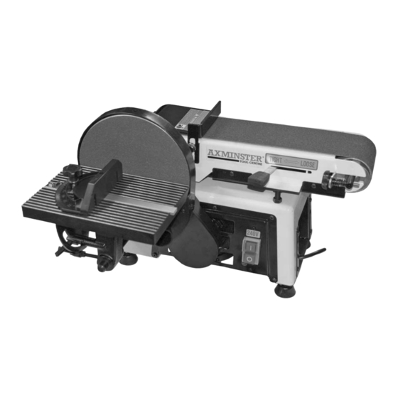
Tensioning lever Tracking adjuster Pointer NVR On/Off switch Scale Pointer A AS408 Belt & Disc Sander G 200mm Cast Iron Disc Plate B Mitre Fence H Workstop Plate C Dust Extraction Moulding I Sanding Belt D Table Support Steel Rod... - Page 19 Illustration & Parts Description... A X M I N S T E R W H I T E Fig 48 Linisher Linisher’s back guard Motor Motor guard Spanners Dust deflector Linisher’s back guard dust deflector plate Loosen the two phillips screws & pull the deflector plate down & tighten the screws.
- Page 20 Illustration & Parts Description... A X M I N S T E R W H I T E Fig 49 Configuration 1 Table to Linisher Fig 50 Configuration 2 Workstop Plate used as miniature table...
-
Page 21: Sanding Configurations
Sanding Configurations ... A X M I N S T E R W H I T E Fig 54 Fig 51 Surface Sanding Fig 52 Belt Sanding Fig 55 Curve Sanding Fig 53 Bevel Sanding Disc Sanding... -
Page 22: Changing The Sanding Belt
Changing the Sanding Belt... A X M I N S T E R W H I T E DISCONNECT THE SANDER FROM THE MAINS SUPPLY Raise the linisher to the upright position by loosening the two clamping nuts, see figs 1 & 39 &... -
Page 23: Changing The Sanding Disc
Changing the Sanding Disc... A X M I N S T E R W H I T E DISCONNECT THE SANDER FROM THE MAINS SUPPLY Lift the edge of the disc and, gripping firmly, peel the disc away from the plate; turning the plate as required to free the entire disc. -
Page 24: Troubleshooting
2. Defective or damaged the sander. switch cord. 3. Defective or damaged switch relay. 4. Burned out motor. 4. Contact Axminster Tool Centre on 0800 371822 & asked to be transferred to the“Technical Sales” 5. Blown fuse. department. Machine slows down while 1. -
Page 25: Parts Breakdown
Parts Breakdown... A X M I N S T E R W H I T E... -
Page 26: Parts List
Parts List... A X M I N S T E R W H I T E www.axminster.co.uk... - Page 27 Parts List... A X M I N S T E R W H I T E 0800 371822 FREEPHONE...
- Page 28 Axminster Reference No: AS408 A X M I N S T E R W H I T E...
Need help?
Do you have a question about the AS408 and is the answer not in the manual?
Questions and answers