
Related Manuals for Axminster Workshop AW200BDS


Summary of Contents for Axminster Workshop AW200BDS
- Page 1 Code 107680 Original Instructions AW200BDS Belt & Disc Sander AT: 22/04/2022 BOOK VERSION: 06...
-
Page 2: Eu Declaration Of Conformity
Maintenance Exploded Diagrams/Lists 19-20-21 Wiring Diagram Notes EU DECLARATION OF CONFORMITY Cert No: BD4800 EU Declaration of Conformity Axminster Tool Centre Ltd This machine complies with the following directives: Axminster Devon EX13 5PH UK axminstertools.com 2006/42/EC EN 61000-3-3:2013+A1 2014/30/EU EN IEC 61000-3-2:2019... -
Page 3: What's Included
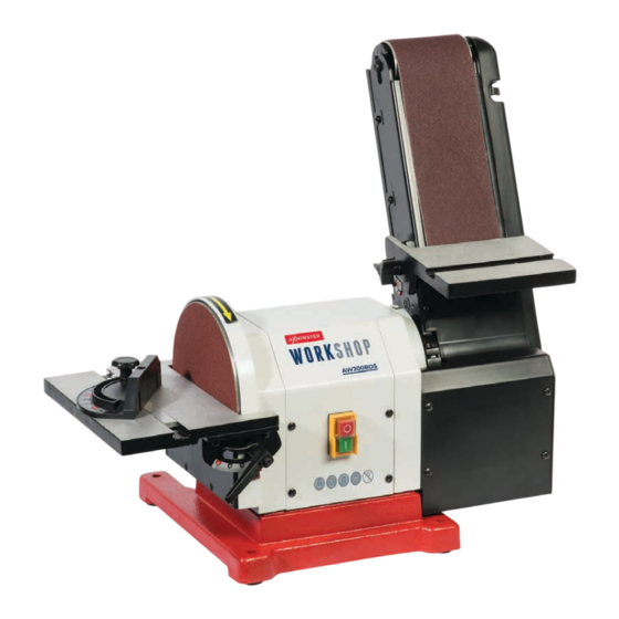
WHAT’S INCLUDED Quantity Item Part Model Number AW200BDS Belt & Disc Sander Linisher Belt Table Sanding Disc Table Dust Extraction Outlet Extraction Outlet Lever Clamp Mitre Fence Disc Table Lift & Shift Handles & Washers Lift & Shift Handle & Washer for Linisher Table Hex Key Instruction Manual NOTE: Please read the Instruction... -
Page 4: General Instructions For 230V Machines
INTRODUCTION This is a neatly designed combined 100mm belt and which helps this machine achieve a high level of dust 200mm disc sander. Unusually, both functions are driven extraction. There is a powered fan in the dust outlet port, directly from the motor spindle, with no belts to worry which helps produce an airflow around both the belt and about. -
Page 5: Specification
SPECIFIC SAFETY PRECAUTIONS FOR SANDING MACHINES DO NOT sand very small pieces of work with bare hands; Always offer the work piece to the belt/disc so that the try to construct some form of holder. motion carries the work against the restraining surface i.e. the work stop or the table (use the right hand side of the Make sure you are comfortable before you start work, disc). - Page 6 ASSEMBLY Extraction port Loosen the caphead bolt Raise the linisher Tighten the caphead bolt Take up the slack and press down the lever to lock in place.
- Page 7 ASSEMBLY Engineer’s square Machined slot Reset the pointer to ZERO Raised quadrant Raised quadrant Threaded hole Continues Over...
- Page 8 ASSEMBLY Raised quadrant Machined slot Secure Engineer’s square...
- Page 9 ASSEMBLY Adjust until square Engineer’s square Clamp the mitre Reset the pointer to ZERO fence in position Reset the pointer to ‘ZERO’ Check the mitre fence (F) is square to the linisher’s belt and adjust if required.
-
Page 10: Illustration And Parts Description
ILLUSTRATION AND PARTS DESCRIPTION Rear view Linisher abrasive belt Belt tracking wheel Linisher Table ‘T’ slot for Linisher table lift mitre fence & shift handle 63mm dust extraction outlet Motor Linisher tilt Sanding disc clamping bolt Mitre fence Cast iron base Sanding disc table ‘T’... - Page 11 ILLUSTRATION AND PARTS DESCRIPTION NVR ON/OFF control switch 63mm dust extraction outlet Linisher belt tracking control wheel Clamping handle (A), Linisher table scale & pointer (B) Sanding disc table scale & pointer Linisher table set at 90˚ degrees Sanding disc table set at 90˚ degrees Linisher table set at 45˚...
-
Page 12: Setup And Adjustment
SET UP AND ADJUSTMENT Setting the Table Clearance DO NOT make large adjustments, and remember the belt may take The gap between the table and the disc should be set to time to react to your alteration. a maximum of 1.6mm to clear the debris and to ensure sufficient support for the timber, see fig 01. - Page 13 OPERATING INSTRUCTIONS MAKE SURE THE SANDER IS ON A FLAT LEVEL SURFACE. NOTE: GO ROUND AND MAKE SURE EVERYTHING IS SECURE, FASTENED DOWN, THAT ALL TOOLS ARE CLEARED AWAY FROM THE WORK AREA! WARNING!! KEEP TOOLS AND EQUIPMENT OUT OF REACH OF YOUNG CHILDREN CONNECT A DUST EXTRACTION MACHINE TO THE SANDER.
-
Page 14: Changing The Abrasive Belt/Disc
CHANGING THE ABRASIVE BELT/DISC Sanding Disc DISCONNECT THE SANDER FROM THE MAINS SUPPLY BEFORE CONTINUING! Lift the edge of the disc and, gripping firmly, peel the disc away from the plate; turning the plate as required to free the entire disc. Clean the surface of the disc, allow to dry off and wipe over with a clean dry cloth. - Page 15 CHANGING THE ABRASIVE BELT/DISC Remove the linisher table (B) assembly, place safely aside. Lift and remove the rear guard, place to one side. Release the belt tension by lifting up the tensioning lever. Remove the lower guard securing screws, place safely aside. Remove the lower guard and place to one side.
- Page 16 CHANGING THE ABRASIVE BELT/DISC Idler drum Drive drum Remove the linisher belt. Inspect the new belt, ensure that there are no tears or rips especially along the edges, check the direction arrows on the inner surface of the belt and fit accordingly.
- Page 17 CHANGING THE ABRASIVE BELT/DISC Replace the lower guard assembly. Replace the lower guard front screw. Replace the rear guard assembly. Lower the tension lever to re-tension the linisher belt. Replace the linisher table (B) assembly. CLEAR ALL TOOLS AWAY FROM THE WORK AREA.
-
Page 18: Maintenance
MAINTENANCE DISCONNECT THE SANDER FROM THE MAINS SUPPLY BEFORE CONTINUING! ALWAYS WEAR EYE PROTECTION AND DUST MASK BEFORE CONTINUING. There is very little mechanical maintenance that can be carried out on the machine. Most prudent maintenance is preventative and concerned with keeping the machine clean. - Page 19 EXPLODED DIAGRAMS/LISTS...
- Page 20 EXPLODED DIAGRAMS/LISTS Specification Size Phillips Screw M5 × 25 Rubber Foot Belt Tracking Knob Phillips Screw M4 × 10 Flat Washer Bottom Plate Rubber Washer Phillips Screw M8 × 25 Adjust Spring Spring washer Belt Frame Flat washer Tension Spring Base Sleeve Connect Tube...
- Page 21 EXPLODED DIAGRAMS/LISTS Collector Flat Washer Mounting Shaft Inner Hex Screw M5 × 8 Inner Hex Screw M5 × 20 Phillips Screw M4 × 16 Belt Mounting Plate Phillips Screw End Cap Mitre Gauge Pointer Power Cord I Type Hex Nut Cord Sleeve Dust Box Cover Belt Protect Plate...
-
Page 22: Wiring Diagram
WIRING DIAGRAM... - Page 23 NOTES...
- Page 24 The packaging is suitable for recycling. Please dispose of it in a responsible manner. EU Countries Only Do not dispose of electric tools together with household waste material. By law they must be collected and recycled separately. Axminster Tools, Axminster Devon EX13 5PH axminstertools.com...
Need help?
Do you have a question about the Workshop AW200BDS and is the answer not in the manual?
Questions and answers