Table of Contents
Advertisement
Quick Links
PZ280E
P-612 Positioners
User Manual
Version: 1.1.0
Physik Instrumente (PI) GmbH & Co. KG, Auf der Römerstraße 1, 76228 Karlsruhe, Germany
Phone +49 721 4846-0, fax +49 721 4846-1019, e-mail info@pi.ws, www.pi.ws
Date: 12.09.2024
This document describes the following products:
P-612.2
XY piezo nanopositioner
P-612.Z
Piezo Z stage
Advertisement
Table of Contents

Related Manuals for PI P-612


Summary of Contents for PI P-612
- Page 1 This document describes the following products: P-612.2 XY piezo nanopositioner P-612.Z Piezo Z stage Physik Instrumente (PI) GmbH & Co. KG, Auf der Römerstraße 1, 76228 Karlsruhe, Germany Phone +49 721 4846-0, fax +49 721 4846-1019, e-mail info@pi.ws, www.pi.ws...
- Page 2 PI®, NanoCube®, PICMA®, PILine®, NEXLINE®, PiezoWalk®, NEXACT®, Picoactuator®, PInano®, PIMag®, Q-Motion® © 2024 Physik Instrumente (PI) GmbH & Co. KG, Karlsruhe, Germany. The text, photographs and drawings in this manual are protected by copyright. With regard thereto, Physik Instrumente (PI) GmbH & Co. KG retains all the rights.
-
Page 3: Table Of Contents
Strain Gauge Sensors (SGS) ................. 14 Unpacking Installing General Notes on Installation ................... 17 Connecting the P-612 to the Protective Earth Conductor ........18 Mounting the P-612 ....................20 Fixing the Load ......................21 Starting and Operating General Notes on Starting and Operating ..............25 Operating the P-612 .................... - Page 4 Maintenance General Notes on Maintenance ................29 Cleaning the P-612 ....................29 Troubleshooting Customer Service Department Technical Data 10.1 Specifications ......................35 10.1.1 Data Table ....................35 10.1.2 Maximum Ratings ..................38 10.1.3 Ambient Conditions and Classifications ............38 10.2 Dimensions ....................... 39 10.3 Torque for Stainless Steel Screws (A2-70) ..............
-
Page 5: About This Document
Downloading Manuals ........................3 Objective and Target Group of this User Manual This user manual contains the information required for using the P-612 as intended ("x" stands for the different models (p. 9)). Basic knowledge of control technology, drive technologies, and suitable safety measures is assumed. -
Page 6: Figures
Other Applicable Documents The devices and software tools from PI mentioned in this documentation are described in separate manuals. The latest versions of the user manuals are available for download on our website (p. 3). -
Page 7: Downloading Manuals
Contact our customer service department (p. 33). Downloading manuals 1. Open the website www.pi.ws. 2. Search the website for the product number (e.g., P-612). 3. In the search results, select the product to open the product detail page. 4. Select Downloads. -
Page 9: Safety
Organizational Measures ....................... 7 Intended Use The P-612 is a laboratory device as defined by DIN EN 61010-1. It is intended for indoor use and use in an environment that is free from dirt, oil, and lubricants. According to its design, the P-612 is intended for fine positioning as well as moving small objects quickly and precisely. - Page 10 If the protective earth conductor is not or not properly connected, dangerous touch voltages can occur on the P-612 in the event of a malfunction or failure of the system. If there are touch voltages, touching the P-612 can result in minor injuries from electric shock.
-
Page 11: Organizational Measures
Add all information from the manufacturer such as supplements or technical notes to the user manual. If you give the P-612 to other users, include this user manual as well as all other relevant information provided by the manufacturer. -
Page 13: Product Description
XY piezo nanopositioner; 100 µm × 100 µm travel range (X × Y); aperture P-612.2SL 20 mm × 20 mm; SGS, indirect position measuring; LEMO connector; 1.5 m cable length P-612.ZSL Piezo Z stage; 100 μm travel range; SGS, indirect position measuring; LEMO connector; 1.5 m cable length P-612 Positioners PZ280E Version: 1.1.0... -
Page 14: Product View
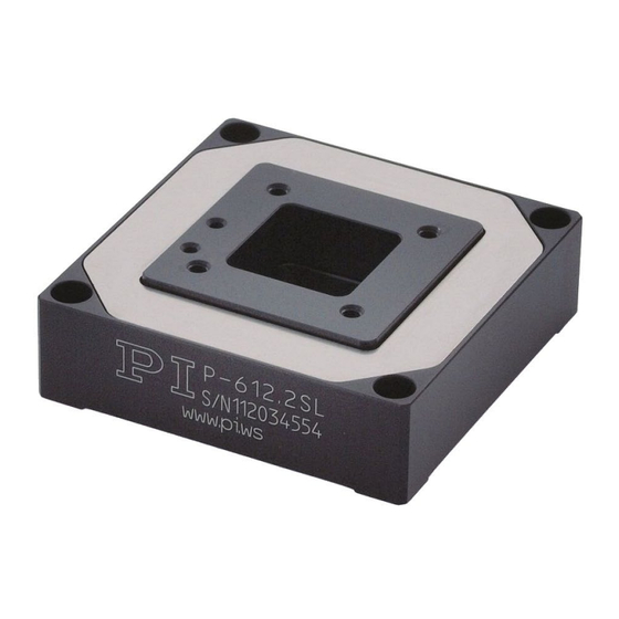
3 Product Description Product View The figure serves as an example and can differ from your positioner model. Figure 1: Exemplary product view of a P-612.2SL Motion platform Piezo voltage connecting cable Sensor connecting cable (depending on model) Protective earth connector Base body Version: 1.1.0... -
Page 15: Product Labeling
Product number (example), the digits after the period refer to the model 123456789 Serial number (example), individual for each P-612 Meaning of each position (from the left): 1 = internal information, 2 and 3 = year of manufacture, 4 to 9 = consecutive number Manufacturer's logo Warning sign "Pay attention to the manual!"... -
Page 16: Scope Of Delivery
PZ240EK Short instructions for P-5xx / P-6xx / P-7xx piezo positioners Suitable Electronics You need suitable electronics to operate a P-612. The device is selected depending on the type of application. Electronics Channels* E-505 piezo amplifier module (plug-in module) -
Page 17: Optional Accessories
Technical Features 3.7.1 PICMA® Piezo Actuators P-612 positioners are driven by PICMA® piezo actuators. PICMA® actuators have all-ceramic insulation and their performance and lifetime are therefore far superior to conventional actuators. The ceramic insulation layer protects the monolithic piezoceramic block against humidity and failure due to increased leakage current. -
Page 18: Strain Gauge Sensors (Sgs)
The sensors operate in thermally drift-free full bridge circuitry and therefore ensure optimum position stability in the nanometer range. Version: 1.1.0 PZ280E P-612 Positioners... -
Page 19: Unpacking
NOTICE Mechanical overload due to incorrect handling! An impermissible mechanical load on the motion platform of the P-612 can cause damage to the piezo actuators, sensors, and flexures of the P-612 as well as loss of accuracy. Do not touch any sensitive parts (e.g., motion platform) when handling the P-612. -
Page 21: Installing
NOTICE Mechanical overload due to incorrect handling! An impermissible mechanical load on the motion platform of the P-612 can cause damage to the piezo actuators, sensors, and flexures of the P-612 as well as loss of accuracy. Do not touch any sensitive parts (e.g., motion platform) when handling the P-612. -
Page 22: Connecting The P-612 To The Protective Earth Conductor
Improper mounting of the P-612 or incorrectly mounted parts can damage the P-612. Only use the holes or threads intended for the purpose of fixing the P-612 and loads. Install the P-612 so that the platform and all parts attached to it can move freely within the entire travel range. - Page 23 1. If necessary, firmly attach a suitable cable lug to the protective earth conductor. 2. Use the M4 screw (together with the flat and lock washers) to attach the cable lug of the protective earth conductor to the threaded hole in the P-612 as shown in the profile view.
-
Page 24: Mounting The P-612
Fixing the P-612 onto an uneven surface can warp the P-612. Warping reduces the accuracy. Fix the P-612 onto a flat surface. The recommended flatness of the surface is ≤ 100 µm. For applications with large temperature fluctuations: Only fix the P-612 onto surfaces that have the same or similar thermal expansion properties as the P-612 (e.g., surfaces made of aluminum). -
Page 25: Fixing The Load
Suitable screwdriver Mounting the P-612 1. Align the P-612 on the surface so that the corresponding mounting holes in the base body (see figure) and the surface are in line. 2. Fix the P-612 with the screws: a) Insert a screw into each hole. - Page 26 Fixing loads with an uneven contact surface could warp the P-612. Warping reduces the accuracy. Fix loads to the P-612 only when the surface contacting the P-612's platform has a flatness of at least 100 μm. For applications with large temperature fluctuations: Fix loads to the P-612 only when they have the same or similar thermal expansion properties as the P-612 (e.g., loads made of aluminum).
- Page 27 Unwanted lever effect and center of load on the side of the platform Figure 9: Mounting holes in the motion platform of the P-612 (example view from above) Requirements You have read and understood the General Notes on Installation (p. 17).
- Page 28 Fixing the load 1. Align the load on the P-612 so that the mounting holes in the load and motion platform are in line. 2. Insert the screws through the holes in the load into the selected mounting holes in the motion platform of the P-612.
-
Page 29: Starting And Operating
If the protective earth conductor is not or not properly connected, dangerous touch voltages can occur on the P-612 in the event of a malfunction or failure of the system. If there are touch voltages, touching the P-612 can result in minor injuries from electric shock. -
Page 30: Operating The P-612
Positive direction of axis motion is specified in the product view (p. 10). INFORMATION Sound and vibration (e.g., footfall, knocks) can be transmitted to the P-612 and can affect its performance with regard to position stability. Avoid sound and vibration while the P-612 is being operated. -
Page 31: Discharging The P-612
The P-612 must be discharged in the following cases: Before Installation When the P-612 is not used but the electronics remain switched on to ensure temperature stability Before demounting (e.g., before cleaning and transporting the P-612 and for ... -
Page 33: Maintenance
General Notes on Maintenance NOTICE Misalignment due to loosening screws! The P-612 is maintenance-free and achieves its positioning accuracy as a result of the optimal alignment of mechanical components and piezo actuators. Loosened screws cause a loss in positioning accuracy. - Page 34 7 Maintenance Cleaning the P-612 Clean the surfaces of the P-612 with a cloth dampened with a mild cleanser or disinfectant (e.g., isopropyl alcohol). Version: 1.1.0 PZ280E P-612 Positioners...
-
Page 35: Troubleshooting
(21 to 24 °C) Reduced accuracy The base body or the Mount the P-612 onto surfaces with the motion platform is warped following characteristics only: − Flatness of at least 100 μm − The thermal expansion properties are similar to those of the P-612 (e.g., surfaces made of... - Page 36 8 Troubleshooting Problem Possible causes Solution P-612 is not connected to Pay attention to the assignment of the the corresponding devices when several systems are controller (only when there connected. The assignment is indicated are several systems) on the calibration label of the controller...
-
Page 37: Customer Service Department
9 Customer Service Department Customer Service Department For inquiries and orders, contact your PI representative or send us an email (service@pi.de). If you have questions concerning your system, provide the following information: − Product and serial numbers of all products in the system −... -
Page 39: Technical Data
Resolution in Y, open loop 0.8 nm typ. Integrated sensor SGS, indirect position measuring System resolution in X 5 nm System resolution in Y 5 nm Drive properties P-612.2SL Tolerance Drive type PICMA® Electrical capacitance 1.5 µF ±20 % P-612 Positioners PZ280E Version: 1.1.0... - Page 40 The resolution of the system is limited only by the noise of the amplifier and the measuring technology because PI piezo nanopositioning systems are free of friction. At PI, technical data is specified at 22 ±3 °C. Unless otherwise stated, the values are for unloaded conditions. Some properties are interdependent. The designation "typ." indicates a statistical average for a property;...
- Page 41 Recommended controllers/drivers E-503, E-505, E-610, E-621, E-625, E-665 The resolution of the system is limited only by the noise of the amplifier and the measuring technology because PI piezo nanopositioning systems are free of friction. P-612 Positioners PZ280E Version: 1.1.0...
-
Page 42: Maximum Ratings
10 Technical Data At PI, technical data is specified at 22 ±3 °C. Unless otherwise stated, the values are for unloaded conditions. Some properties are interdependent. The designation "typ." indicates a statistical average for a property; it does not indicate a guaranteed value for every product supplied. -
Page 43: Dimensions
10 Technical Data 10.2 Dimensions Figure 10: P-612.2SL, dimensions in mm. Note that the decimal points are separated by a comma in the drawings. P-612 Positioners PZ280E Version: 1.1.0... - Page 44 10 Technical Data Figure 11: P-612.ZSL, dimensions in mm. Note that the decimal points are separated by a comma in the drawings. Version: 1.1.0 PZ280E P-612 Positioners...
-
Page 45: Torque For Stainless Steel Screws (A2-70)
Function Connector (contact side) shell Inner Input Piezo voltage Ground conductor -20 to 120 V Input Supply voltage for strain gauge Cable shield sensor Output Sensor signal 1 Output Sensor signal 2 Supply voltage ground P-612 Positioners PZ280E Version: 1.1.0... -
Page 47: Old Equipment Disposal
PI equipment made available on the market after 13 August 2005 without charge. If you have an old device from PI, you can send it to the following address free of charge: Physik Instrumente (PI) GmbH & Co. KG... - Page 49 12 European Declarations of Conformity European Declarations of Conformity For the P-612, declarations of conformity were issued according to the following European statutory requirements: Low Voltage Directive EMC Directive RoHS Directive The standards applied for certifying conformity are listed below.
Need help?
Do you have a question about the P-612 and is the answer not in the manual?
Questions and answers