Table of Contents

Related Manuals for Fluke Biomedical ProSim 8


Summary of Contents for Fluke Biomedical ProSim 8
- Page 1 ProSim™ 8 Vital Signs Simulator Users Manual January 2011, Rev. 3, 3/16 © 2011-2016 Fluke Corporation. All rights reserved. Specifications are subject to change without notice. All product names are trademarks of their respective companies.
- Page 2 OR two years if at the end of your first year you send the instrument to a Fluke Biomedical service center for calibration. You will be charged our customary fee for such calibration. During the warranty period, we will repair or at our option replace, at no charge, a product that proves to be defective, provided you return the product, shipping prepaid, to Fluke Biomedical.
- Page 3 Order Entry Group Repair and calibration: To ensure the accuracy of the Product is maintained at a high level, Fluke Biomedical recommends the product be calibrated at least once every 12 months. Calibration must be done by qualified personnel. Contact your local...
- Page 4 Changes made to the information in this document will be incorporated in new editions of the publication. No responsibility is assumed by Fluke Biomedical for the use or reliability of software or equipment that is not supplied by Fluke Biomedical, or by its affiliated dealers.
-
Page 5: Table Of Contents
Table of Contents Title Page Introduction .................... 1 Intended Use ..................1 Safety Information ................. 2 Symbols ....................3 Unpack the Product ................4 Accessories ................... 4 Instrument Familiarization ..............6 Turn On the Product ................8 Connect a PC to the Product ..............9 Pre-Defined Simulations ................ - Page 6 ProSim™ 8 Users Manual Simulate Respiration ................40 Simulate Cardiac Output ............... 42 Set the Cardiac Output Waveform ............. 45 Set the Baseline Temperature ............45 Set Injectate Temperature ..............45 Start a Cardiac Output Simulation ............. 45 Non-Invasive Blood Pressure Simulation and Tests ......46 Set the Non-Invasive Blood Pressure Variables ........
- Page 7 Contents (continued) Temperature ..................88 Cardiac Output .................. 88 Non-Invasive Blood Pressure ............89 Oximeter SpO2 Optical Emitter and Detector (optional) ....89 Pre-Defined Simulations ..............90 Autosequences (default) ..............90 Glossary ....................A1 Introduction .................... A1...
- Page 8 ProSim™ 8 Users Manual...
- Page 9 List of Tables Table Title Page Simulation Types ..................1 Symbols ..................... 3 Standard Accessories ................4 Optional Accessories ................. 5 Top-Panel Controls and Connections ............6 Back, Front, and Side-Panel Connections ..........7 Pre-Defined Patient Simulations ............... 10 ECG Wave Groups ..................13 ECG Lead Amplitudes ................
- Page 10 ProSim™ 8 Users Manual...
- Page 11 List of Figures Figure Title Page Power-Up Screen ..................8 Home Screen .................... 8 Laptop to PC Connection ................9 ECG Connections ..................12 ECG Screen ....................12 ECG Graph Screen ................... 15 ECG NSR Adult Screen ................15 Performance Wave Screen ............... 23 R Wave Detection Screen .................
- Page 12 ProSim™ 8 Users Manual Leak Test Pumping Screen ............... 53 Example Leak Test Result Screen ............54 Pressure Relief Valve Test Results Screen ..........55 Pressure Source Connection ..............56 Pressure Source Pumping Screen ............57 Manometer Connections ................57 Manometer Screen ..................
-
Page 13: Introduction
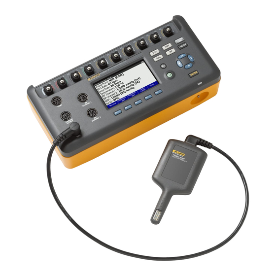
Introduction The Fluke Biomedical ProSim™ 8 Vital Signs Simulator (hereafter the Product) is a full-featured, compact, portable simulator, used to measure the performance of patient monitors. The Product simulates: • ECG Functions • Respiration • Invasive and Non-Invasive Blood Pressure •... -
Page 14: Safety Information
ProSim 8 Users Manual The intended user is a trained biomedical equipment technician who performs periodic preventative maintenance checks on patient monitors in service. Users can be associated with hospitals, clinics, original equipment manufacturers and independent service companies that repair and service medical equipment. The end user is an individual, trained in medical instrumentation technology. -
Page 15: Symbols
Vital Signs Simulator Symbols • Replace the batteries when the low battery indicator shows to prevent incorrect measurements. • Remove the batteries if the Product is not used for an extended period of time, or if stored in temperatures above 50 °C. -
Page 16: Unpack The Product
Afterwards, charge the battery when the Product shows the low battery message. See Battery Maintenance. Accessories Available Product accessories are shown in Tables 3 and 4. Table 3. Standard Accessories Item Fluke Biomedical Part Number ProSim™ 8 Getting Started Manual 3984515 AC/DC Power Supply 4219453 2201455... - Page 17 3985658 Masimo RAINBOW cable 4034609 Battery pack 4021085 NIBP Test 500 mL rigid chamber 4034611 Simulation Cables: See your Fluke Biomedical Distributor Temperature Cardiac Output Interface Box 2392199 Upgrade kit to ProSim™ 8 3987196 USB Wireless Dongle 3341333 Mini-DIN to DIN IBP Adapter...
-
Page 18: Instrument Familiarization
ProSim 8 Users Manual Instrument Familiarization Table 5 is a list of Product top-panel controls and connections. Table 5. Top-Panel Controls and Connections glh034.eps Item Name Description ECG Posts Connection posts for Device Under Test (DUT) ECG leads. Accesses the ECG waveforms (adult, pediatric, and arrhythmias),... - Page 19 Vital Signs Simulator Instrument Familiarization Table 6 is a list of controls on the back, front, and side of the Product. Table 6. Back, Front, and Side-Panel Connections Back Front Right glh035.eps Item Name Description AC/DC Supply Connector Input jack for the DC output of the AC/DC supply connector. ...
-
Page 20: Turn On The Product
ProSim 8 Users Manual Turn On the Product Push on the front panel to turn on the Product. The screen shown in Figure 1 shows the Power-Up screen. glh002.bmp Figure 1. Power-Up Screen When the self test is complete and no errors are sensed, the Home screen in Figure 2 shows on the display. -
Page 21: Connect A Pc To The Product
Vital Signs Simulator Connect a PC to the Product Connect a PC to the Product You can use a PC to store presets, auto sequences, and test results from the Product. You must use the ProSim Mini Plug-In on the PC to communicate with the Product. -
Page 22: Pre-Defined Simulations
ProSim 8 Users Manual Pre-Defined Simulations The pre-defined simulations are set through the softkeys along the bottom of the Home screen. See Figure 2. There are seven factory pre-defined simulations: normal, hypertensive, hypotensive, tachycardic, bradycardic, heart attack, and asystole. A More softkey shows on the display for more simulations. Table 7 lists the parameter values for each pre-defined simulation. - Page 23 Vital Signs Simulator Pre-Defined Simulations Table 7. Pre-Defined Patient Simulations (cont.) Simulation Name Parameter Pre-Set Value Wave Form NSR (Adult) ECG Rate 30 BPM Respiration Rate 15 brpm 35.0 °C Temperature Bradycardic IBP Channel 1 100/65 mmHg (Art) IBP Channel 2 25/10 mmHg (PA) NIBP 100/65 (77) mmHg...
-
Page 24: Ecg Function
ProSim 8 Users Manual ECG Function The Product simulates normal heart signals (ECG) as well as heart signals for a variety of arrhythmias. Heart rate (beats per minute), signal amplitude, and ST segment elevation are all controlled by the Product through the user interface. - Page 25 Vital Signs Simulator ECG Function To change the ECG waveform: 1. Push or to move the highlight to the Wave Group value. 2. Push . 3. Push or to move the highlight to a waveform group name. Table 8 is a list of the wave groups available in the Product.
- Page 26 ProSim 8 Users Manual To set the ST Deviation: 1. Push or to move the highlight to the ST Deviation value. 2. Push . 3. Push or to adjust the deviation. Each push of a key moves the deviation 0.05 or 0.1 mV in the direction of the key pushed.
-
Page 27: View The Ecg Waveform
Vital Signs Simulator ECG Function View the ECG Waveform As you adjust the ECG signal, you can see the signal on the display. To see the ECG signal, from the ECG screen, push the Graph softkey. The ECG: Graph screen in Figure 6 shows on the display. glh023.bmp Figure 6. -
Page 28: Simulate Arrhythmias
ProSim 8 Users Manual To change the size of the artifact: 1. From the ECG screen, push or to highlight the Artifact Size value. 2. Push or to highlight 100%, 50%, or 25%. 3. Push to set the artifact size and go back to the ECG screen. - Page 29 Vital Signs Simulator ECG Function Table 10. Arrhythmias by Wave Group (cont.) Arrhythmia Wave Group Multi-focal PVCs Premature Myocardial Infarctions ACLS Narrow Complex Tach ACLS Nodal PNC Premature Nodal Rhythm Supraventricular Non-Capture TV Paced Non-Function TV Paced Paroxysmal ATach Supraventricular Poly V Tach Ventricular Poly V Tach (unstable)
-
Page 30: Supraventricular Arrhythmias
ProSim 8 Users Manual Supraventricular Arrhythmias To set a supraventricular arrhythmia: 1. From the ECG screen, push or to highlight the Wave Group value. 2. Push . 3. Push or to highlight Supraventricular in the wave group list. -
Page 31: Ventricular Arrhythmias
Vital Signs Simulator ECG Function Ventricular Arrhythmias Ventricular arrhythmias are arrhythmias in the lower chambers of the heart, or ventricles. To do a ventricular arrhythmia: 1. From the ECG screen, push or to highlight the Wave Group value. 2. -
Page 32: Conduction Arrhythmias
ProSim 8 Users Manual The Run of PVCs arrhythmia has a number variable to set the number of PVCs in a run. To change the number of PVCs in a run: 1. Push or to highlight the Number value. - Page 33 Vital Signs Simulator ECG Function To select a pacemaker waveform simulation: 1. From the ECG screen, push or to highlight the Wave Group value. 2. Push . 3. Push or to highlight TV Paced in the wave group list. 4.
-
Page 34: Advance Cardiac Life Support (Acls) Waveforms
ProSim 8 Users Manual To change the polarity: 1. Push or to highlight the Polarity value. 2. Push . 3. Push or to highlight + or - in the list. 4. Push to set the polarity and go back to the TV Paced Settings screen. - Page 35 Vital Signs Simulator ECG Function glh019.bmp Figure 8. Performance Wave Screen To change the waveform: 1. Push or to highlight the Waveform value. 2. Push . 3. Push or to highlight Square, Sine, Triangle, or Pulse in the list. 4.
-
Page 36: Set R Wave Detection Values
ProSim 8 Users Manual Set R Wave Detection Values To sense a heartbeat, a monitor looks for R waves. The sensed R wave is used to calculate heart rate and other analysis. You adjust the R wave to find the range of values a heart monitor can sense a heartbeat. -
Page 37: Set Qrs Detection Test Values
Vital Signs Simulator ECG Function To change the width of the R Wave: 1. Push or to highlight the Width value. 2. Push . 3. Push or to adjust the width. Each push of a key increases or decreases the width 20 ms for each key push when the value is 20 ms or above and 2 ms when the value is 20 ms or less. -
Page 38: Set Tall T Wave Rejection Test Values
ProSim 8 Users Manual To change the QRS Wave amplitude: 1. Push or to highlight the Amplitude value. 2. Push . 3. Push or to adjust the amplitude. Each push of a key increases or decreases the amplitude in the direction of the key pushed. The Product simulates a heart signal amplitude of 0.05 mV to 0.25 mV by 0.05 mV... -
Page 39: Fetal Simulation
Vital Signs Simulator Fetal Simulation You can change the amplitude of the T Wave. To change the amplitude: 6. Push or to highlight the Amplitude value. 7. Push . 8. Push or to increase or decrease the T Wave amplitude. The amplitude is set as a percentage of the voltage on the reference lead. -
Page 40: Simulate Intrauterine Pressure (Iup)
ProSim 8 Users Manual To change the fetal heart rate: 1. Push or to highlight the Fetal HR value. 2. Push . 3. Push or to change the heart rate value in 1 BPM steps between 60 BPM and 240 BPM. - Page 41 Note The maternal thigh reference plate is an accessory provided by fetal monitor OEM, not by Fluke Biomedical, for internal FHR and FECG recording. The 3-lead leg plate employs a single skin electrode as a reference, positioned on the mother's thigh.
-
Page 42: Set The Fetal Heart Rate Response
ProSim 8 Users Manual To simulate intrauterine pressure contractions push the IUP Contraction softkey to show the Fetal ECG: IUP screen on the display. See Figure 14. glh026.bmp Figure 14. Intrauterine Pressure Contractions Screen Set the Fetal Heart Rate Response The Product simulates three types of preconfigured waveforms for a periodic fetal heart rate that is interactive with uterine contractions: early deceleration;... -
Page 43: Invasive Blood Pressure Simulation And Tests
Vital Signs Simulator Invasive Blood Pressure Simulation and Tests the display and updates with real-time simulation data. The time until the contraction ends is also shows on the display. See Figure 15. glh027.bmp Figure 15. Fetal ECG Intrauterine Pressure Screen If the Contraction value is set to Manual Start, only one contraction cycle is simulated. - Page 44 ProSim 8 Users Manual To set the chamber: 1. Push or to highlight the Chamber value on Channel 1 or Channel 2. 2. Push . 3. Push or to highlight a value in the chamber list. Below is a list of chamber values in the Product.
-
Page 45: Simulate Invasive Blood Pressure Tests
The Product can simulate pressures that occur during a Swan-Ganz or Cardiac Catheterization procedure. Figure 18 shows a monitor connected to the two IBP channel jacks on the Product. IBP Cables ProSim 8 Patient Monitor glh028.eps Figure 18. Invasive Blood Pressure Connections... -
Page 46: Simulate A Swan-Ganz Procedure
ProSim 8 Users Manual Simulate a Swan-Ganz Procedure To simulate IBP during a Swan-Ganz procedure: 1. Push the Tests softkey in the IBP screen. 2. Push or to highlight Swan-Ganz – Channel 1 or Swan-Ganz – Channel 2. -
Page 47: Simulate A Cardiac Catheterization Procedure
Vital Signs Simulator Invasive Blood Pressure Simulation and Tests You can go back a step when you push the Previous softkey. The Product simulates that step for a full 15 seconds before it does the subsequent step. When you push the Previous softkey while paused, the Product goes back a step, but stays paused and sets the time to 15 seconds. - Page 48 ProSim 8 Users Manual Aortic Valve Catheterization Simulation The aortic valve controls flow from the left ventricle (LV) to the aorta (atrial pressure) and prevents flow in the reverse direction. Both IBP channels are set the Arterial 120/80. IBP channel 1 stays at arterial 120/80 for reference throughout the simulation.
- Page 49 Vital Signs Simulator Invasive Blood Pressure Simulation and Tests Pulmonary Valve Catheterization Simulation The pulmonary valve controls flow from the right ventricle (RV) to the pulmonary artery (PA) and prevents flow in the reverse direction. Both IBP channels are set to PA 25/10.
- Page 50 ProSim 8 Users Manual Mitral Valve Cahteterization Simulation The mitral valve controls flow from the left atrium (LA) to the left ventricle (LV) and prevents flow in the reverse direction. A mitral valve test is done indirectly with pressure measurements in the pulmonary artery (PA). There are two measurements: normal and wedged.
-
Page 51: Simulate Temperature
Inc. (YSI) Series 400 and 700 probes. The type of cable connected to the temperature jack sets the type of temperature probe simulated. Connect the temperature input of the UUT to the Temperature jack as shown in Figure 24. Temperature Cable ProSim 8 Patient Monitor glh038.eps Figure 24. Temperature Simulation Connection To set the simulated temperature: 1. -
Page 52: Simulate Respiration
ProSim 8 Users Manual Simulate Respiration Respiration variables are set through the special functions. To set respiration: 1. Push . 2. Push , , , or to highlight Respiration. 3. Push . The Respiration screen in Figure 25, shows on the display. - Page 53 Vital Signs Simulator Simulate Respiration To set the respiration amplitude: 1. Push or to highlight the Amplitude value. 2. Push . 3. Push or to change the amplitude in 0.05 Ω steps between 0.00 Ω and 5.00 Ω.
-
Page 54: Simulate Cardiac Output
ProSim 8 Users Manual Simulate Cardiac Output The Cardiac Output function electronically simulates the dynamic temperature changes in the blood of the patient during a thermal dilution cardiac output measurement. Thermal dilution cardiac output measurements are given by the heat interchange between the blood of the patient and a known volume of chilled saline put into the heart. - Page 55 ASSEMBLY of the GENERAL PURPOSE CONNECTOR eic224.eps Figure 26. Cardiac Output Injectate Cable Modification Note Fluke Biomedical offers optional adapter cables to connect the Product to specified brands of cardiac output measurement devices. • To examine Hewlett Packard Merlin systems, a cardiac output adapter and a temperature adapter are necessary.
- Page 56 ProSim 8 Users Manual Patient Monitor ProSim 8 Blood Temperature Connection Injectate Temperature Connection Cardiac Output Adapter glh057.eps Figure 27. Cardiac Output Connections Setup the DUT for the simulated parameters that follow: • Catheter Size: 7 F • Injectate Volume: 10 cc •...
-
Page 57: Set The Cardiac Output Waveform
Vital Signs Simulator Simulate Cardiac Output Set the Cardiac Output Waveform To set the cardiac output waveform: 1. In the Cardiac Output screen, use or to highlight the wave parameter. 2. Push . 3. Push or to highlight a waveform name in the list of waveforms. Table 13 shows the cardiac output waveforms for the Product. -
Page 58: Non-Invasive Blood Pressure Simulation And Tests
ProSim 8 Users Manual Non-Invasive Blood Pressure Simulation and Tests The Product simulates blood pressure for Non-Invasive blood pressure monitors. You can set each blood pressure variable through the front-panel controls. The Product also does leak, pressure source, and pressure relief tests. The manometer function sets the Product to measure static pressure and shows the pressure on the display. - Page 59 Vital Signs Simulator Non-Invasive Blood Pressure Simulation and Tests Figure 30 shows the blood pressure cuff mandrel sizes. Large Adult Adult Small Adult Child Small Child Neonatal fcv011.eps Figure 30. Blood Pressure Cuff Mandrel Sizes To set the blood pressure simulation, push to show the NIBP screen in Figure 31 on the display.
- Page 60 ProSim 8 Users Manual Pressure, heart rate, pulse volume, brand, and wave are set through the front- panel controls to simulate different patient conditions. Arrhythmia waveforms are also simulated in the NIBP simulation (set through ECG). To set the Blood Pressure: 1.
- Page 61 Vital Signs Simulator Non-Invasive Blood Pressure Simulation and Tests To set the pulse volume: 1. Push or to highlight the Pulse Volume variable. 2. Push . 3. Push or to increase or decrease the pulse volume in 0.05 mL steps. The pulse volume range is 0.10 mL to 1.25 mL.
-
Page 62: Adjust Nibp Pulse Envelope
ProSim 8 Users Manual Adjust NIBP Pulse Envelope To modify the shift of the blood pressure envelope in the Product with firmware 2.00: 1. Push to show the NIBP screen. 2. Push or to highlight Envelope Shift. -
Page 63: Do An Nibp Monitor Test
Vital Signs Simulator Non-Invasive Blood Pressure Simulation and Tests Do an NIBP Monitor Test To do an accuracy test on an NIBP monitor: 1. Connect the NIBP monitor to the Product as shown in Figure 35. 2. Start an NIBP pressure cycle on the monitor. Refer to the monitor manual as necessary. -
Page 64: Do A Pressure Leak Test
ProSim 8 Users Manual Do a Pressure Leak Test The leak test measures leaks in a non-invasive blood pressure monitor, the hoses connected to the monitor, and the pressure cuff. Note Before you do a pressure leak test on a monitor, do the pressure leak test without the monitor to identify the leak rate of the Product. - Page 65 Vital Signs Simulator Non-Invasive Blood Pressure Simulation and Tests To perform a leak test: 1. Push to show the NIBP screen. 2. Push the Tests softkey. 3. Push or to highlight Leak Test. 4. Push to show the NIBP: Leak Test screen in Figure 36 on the display. glh024.bmp Figure 36.
-
Page 66: Do A Pressure Relief Test
ProSim 8 Users Manual The pump stops when the measured pressure is the same as the target pressure. The Product waits for a time to let the pressure to become stable. Then the Product starts to measure and monitor the pressure for the test period. - Page 67 Vital Signs Simulator Non-Invasive Blood Pressure Simulation and Tests The Product pressurizes the pneumatic system to the target pressure with the pressure measurement and a graph of the pressure shown on the display. See Figure 37. When the Product senses the pressure valve has opened, the test stops and the results show on the display.
-
Page 68: Do A Pressure Source Test
ProSim 8 Users Manual Do a Pressure Source Test The pressure source test is used to pressurize a pneumatic system while it measures the pressure. You can use the pressure source test for static calibration of non-invasive blood pressure measurement systems, sphygmomanometer checks, and other devices that measure pressure. -
Page 69: Check A Manometer
The manometer function sets the Product up as a pressure gauge to measure pressure supplied by an external source. To measure pressure: 1. Connect the pressure port to a pneumatic system as shown in Figure 42. ProSim 8 Blood Pressure Gauge Squeeze Pressure Pump glh050.eps... -
Page 70: Zero Pressure
ProSim 8 Users Manual 3. Push or to highlight Manometer. 4. Push . The NIBP: Manometer screen in Figure 43 shows on the display. glh011.bmp Figure 43. Manometer Screen As the external generator increases the pressure, the digital and analog pressure values on the display show the current pressure. - Page 71 Vital Signs Simulator Oximeter SpO2 Optical Emitter and Detector W Warning The pulse oximeter component of the device is not intended to validate the SpO accuracy of pulse oximeter equipment. The pulse oximeter component of this device is not intended to confirm the SpO accuracy of the calibration curve of the pulse oximeter monitor or to assess the optical characteristics of...
- Page 72 ProSim 8 Users Manual Patient ProSim 8 Monitor Pulse Oximeter Sensor ProSim Oximeter SpO Optical Emitter and Detector Cable glh029.eps Figure 45. Oximeter SpO Optical Emitter and Detector Connections Note When you put the oximeter sensor on the artificial finger, make sure the red LEDs (light emitting diodes) are on the bottom.
- Page 73 Vital Signs Simulator Oximeter SpO2 Optical Emitter and Detector ProSim 8 Patient Monitor Cable ENTER Pulse Oximeter Sensor ProSim Oximeter SpO Optical Emitter and Detector Adjust finger on the display for maximum signal. glh048.eps Figure 46. SpO Sensor Placement Attach the artificial finger to the magnetic holder on the right side of the Product...
-
Page 74: Set The Spo
ProSim 8 Users Manual ProSim 8 Finger Module glh045.eps Figure 47. Magnetic Holder for SpO Artificial Finger Set the SpO Parameters You can raise or lower the degree of oxygen saturation. To change the SpO value: 1. Push or to highlight the SpO value. - Page 75 Vital Signs Simulator Oximeter SpO2 Optical Emitter and Detector To change the transmission value: 1. From the SpO2 screen, push or to highlight the Transmission value. 2. Push . 3. Push or to highlight Dark, Thick Finger, Medium Finger, Light, Thin Finger, and Neonatal Foot.
-
Page 76: Test A Masimo Rainbow Spo
ProSim 8 Users Manual The manufacturer must be known before you do a pulse oximeter test, optically through an artificial finger. For Masimo, you need to know if the sensor is a 2 wavelength or Rainbow sensor. You can configure the Product for the make of pulse oximeter(s) used for the test. -
Page 77: Perform An Oximeter Limits Test
Vital Signs Simulator Autosequences Perform an Oximeter Limits Test Most oximeters have alarms that you can set for the parameters it measures. You can use the Product to trip the alarm as a test. Connect the Oximeter to the Product as shown in Figure 45. Oxygen Limits Test You do a sensitivity test on an oximeter through SpO value adjustments. - Page 78 ProSim 8 Users Manual Table 14 is a list of autosequences that are built into the Product. Table 14. Autosequences Autosequence Sequence Steps Run Time ECG 200 BPM, IBP1 (Arterial, 200/150), IBP2 (PA, 45/25), SpO 100 %, NIBP 200/150, Respiration 80 brpm 01:30 and Temperature 42 °C...
- Page 79 Vital Signs Simulator Autosequences Table 14. Autosequences (cont.) Autosequence Sequence Steps Run Time NSR (Adult) 80 BPM 00:45 Premature PVC1 Left Vent 00:30 Ventricular Mono VTach 00:30 Cardiac Failure Ventricular Ventricular Fibrillation 00:30 Ventricular Asystole 00:25 STOP Total Time 02:30 NSR (Adult) 80 BPM 00:20 NSR (Adult) 120 BPM...
-
Page 80: View The Steps Of An Autosequence
ProSim 8 Users Manual Table 14. Autosequences (cont.) Autosequence Sequence Steps Run Time Waveform: Square; Rate: 2.0 Hz; Amplitude: 1.0 mV 00:05 Waveform: Sine; Rate: 0.05 Hz; Amplitude: 1.0 mV 00:05 Waveform: Sine; Rate: 0.5 Hz; Amplitude: 1.0 mV 00:05 Waveform: Sine;... -
Page 81: Do An Autosequence
Vital Signs Simulator Autosequences The screen shown in Figure 48 is the Temperature Sequence in the autosequence list. glh032.eps Figure 48. Autosequence Start Screen The details of the autosequence show the sequence does each of the four steps and stops. Although this example does not repeat, some autosequences do. The screen also shows the four-step sequence takes 1 minute and 20 seconds to complete. -
Page 82: Save And View Test Results
ProSim 8 Users Manual The autosequence screen shows all the simulation parameters which are updated as the Product steps through the sequence. The right part of the screen shows which step the sequence is on and how much time is left to complete the step. -
Page 83: Make An Operator Id
Vital Signs Simulator Save and View Test Results Make an Operator ID Test results are kept in memory by an operator ID. To make a new operator ID: 1. Push . 2. Push or to highlight Test Record ID in the list. 3. -
Page 84: Make A Test Id
ProSim 8 Users Manual Make a Test ID As shown in Figure 50, test results data is related to a Test Record ID. This test record ID could identify the device under test. Some examples could be its model number, its serial number, or its asset number. After you input the new Test ID, all results data saved after that point is kept with that test ID until you change the test ID. - Page 85 Vital Signs Simulator Save and View Test Results 1. Push the Save softkey to show the Save screen. The screen in Figure 53 is the save screen for the temperature simulation function. glh039.bmp Figure 53. Save Screen Note The next step is valid only when the Enter Observed softkey shows on the display.
-
Page 86: View Test Results
ProSim 8 Users Manual glh040.bmp Figure 55. Saving Screen The three-digit number is the test result ID. Within the test ID, each saved test results is assigned a number in sequence. When the save operation completes, the display goes back to the screen for the function you just saved. -
Page 87: Print Test Results
Vital Signs Simulator Save and View Test Results 8. Push to show the test results data saved for the test ID. See Figure 57. glh042.bmp Figure 57. Test Results Screen 9. Push or to highlight a test results file. 10. -
Page 88: Delete Saved Data
ProSim 8 Users Manual Delete Saved Data Removal of data from memory is done through the View Memory feature. You can only delete test ID records. When the test ID record is deleted, all saved test results data connected to that test ID is deleted from memory. To remove a test ID record: 1. -
Page 89: Set The Time And Date
Vital Signs Simulator Setup Features Set the Time and Date You can set the date, time, and the format in which they show on the display. From the Setup screen, push or to highlight Date/Time Settings and then push . -
Page 90: Set The Beeper
ProSim 8 Users Manual Set the Beeper You can turn on and off the beeper and set its volume. From the Setup screen, push or to highlight Sound Settings and push . To go back to the Setup screen, push the Back softkey. -
Page 91: Set Battery Settings
Vital Signs Simulator Setup Features Set Battery Settings To help save battery life, you can set the Product to power down (Auto power off) when no buttons are sensed as pushed for a set period of time. You can also set whether or not the battery charges in the Product. -
Page 92: Control The Product Remotely
Ansur plug-in. When you purchase a new Fluke Biomedical analyzer or simulator, you can update your existing Ansur software by installing a new plug-in. Each plug-in module allows you to work only with the options and capabilities you need for the instrument you are testing. -
Page 93: Clean The Product
Vital Signs Simulator Maintenance • Do not disassemble or crush battery cells and battery packs. • Do not put battery cells and battery packs near heat or fire. Do not put in sunlight. • Do not short the battery terminals together. •... -
Page 94: Charge The Battery
ProSim 8 Users Manual Charge the Battery The battery charge level shows in the upper right corner of the display. Shows when the ac/dc power supply is ß connected Shows the battery level when the Product operates on the battery You can charge the battery while it is in or out of the Product. -
Page 95: Battery Removal
Figure 61. Battery Removal To put the battery pack into the Product, align the battery pack with the guides on the Product and push it into the Product until the latch locks. The ProSim 8 battery is not compatible with the ProSim 4. -
Page 96: General Specifications
ProSim 8 Users Manual General Specifications Temperature Operating ............10 °C to 40 °C (50 °F to 104 °F) Storage ............... -20 °C to +60 °C (-4 °F to +140 °F) Humidity ..............10 % to 90 % non-condensing Altitude ..............3000 meters (9843 ft) Size (L x W x H) ............. -
Page 97: Detailed Specifications
Vital Signs Simulator Detailed Specifications USA (FCC) ............47 CFR 15 Intentional Radiators: This device complies with part 15 of the FCC Rules. Operation is subject to the following two conditions: (1) This device may not cause harmful interference. (2) This device must accept any interference received, including interference that may cause undesired operation. (15.19). -
Page 98: Arrhythmia
ProSim 8 Users Manual Arrhythmia Baseline NSR ............80 BPM PVC Focus ............. Left focus, standard timing (except where specified) Supraventricular Arrhythmia ....... Atrial fibrillation (coarse or fine); atrial flutter; sinus arrhythmia; missed beat (one time); atrial tachycardia; paroxysmal atrial tachycardia; nodal rhythm;... -
Page 99: Ecg Artifact
Vital Signs Simulator Detailed Specifications R-wave Detection Waveform............Triangular pulse Rate ..............30 BPM, 60 BPM, 80 BPM, 120 BPM, 200 BPM, and 250 BPM Width ..............8 ms to 20 ms in 2 ms steps, and 20 ms to 200 ms in 10 ms steps Width Accuracy ........... -
Page 100: Respiration
ProSim 8 Users Manual Dynamic Waveforms Types (default pressures) ........Arterial (120/80) Radial artery (120/80) Left ventricle (120/00) Right ventricle (25/00) Pulmonary artery (25/10) Pulmonary-artery wedge (10/2) Right atrium (central venous or CVP) (15/10) Pressure Variability ..........Systolic and diastolic pressures are independently variable in 1 mmHg steps. -
Page 101: Non-Invasive Blood Pressure
Saturation within UUT specific range ..±(1 count + specified accuracy of the UUT) Saturation outside UUT specific range ..monotonic with unspecified accuracy With Fluke Biomedical R-curves 91 % to 100 % ..........±(3 counts + specified accuracy of the UUT) 81 % to 90 % .......... -
Page 102: Pre-Defined Simulations
Masimo that allows the ProSim two wavelength to test the Rainbow multiple wavelength system Compatible Manufacturer Products With manufacturer R-curve ......... Nellcor, Masimo, Nonin, and Nihon Kohden With Fluke Biomedical R-curve ......Mindray, GE-Ohmeda, Philips/HP, and BCI Pre-Defined Simulations Normal Hypertensive... -
Page 103: Glossary
Appendix A Glossary Introduction The words in this glossary are common words used in this manual that may need further explanation. Words in italics are words that are defined in this glossary. AAMI Acronym for the Association for the Advancement of Medical Instrumentation. A group of physicians, biomedical and clinical engineers, nurses, manufacturers, and government representatives who set industry guidelines for the performance and safety of biomedical instrumentation. - Page 104 ProSim™ 8 Users Manual Artifact An abnormal signal or structure produced by an external medium, such as a muscle or electrical wiring. Artifacts are sometimes referred to as noise. An ECG artifact can be caused by depolarization or contraction of the muscle which depends on an electrical charge.
- Page 105 Glossary Introduction Atrial Tachycardia (AT) Normal rhythm at a faster-than-normal rate of 160 BPM. Atrial tachycardia occurs when an ectopic, atrial pacemaker (non-SA) fires repeatedly at a rate between 150 BPM and 250 BPM. AT may cause cardiac output to drop significantly (in some cases by as much as 25 %), due to the inability of the ventricles to fill completely during the typically short diastole.
- Page 106 ProSim™ 8 Users Manual Bundle Of HIS A collection of nerves (about 1 cm in length) that lies just below the AV node in the heart. Part of the heart’s electrical conduction system. With the AV node, forms the AV junction. Below the bundle, the nerves divide into left and right branches.
- Page 107 Glossary Introduction Hemoglobin The oxygen-bearing, iron-containing conjugated protein in vertebrate red blood cells, consisting of about 6 per cent heme and 94 per cent globin. Hertz A unit of frequency equal to one cycle per second. Used to measure electrical current and light, especially ultraviolet radiation (as in fluorescent light).
- Page 108 ProSim™ 8 Users Manual Nanometer One-billionth (10 ) of a meter. Nanosecond One billionth (10 ) of a second (one thousand-millionth of a second). Electricity travels approximately one foot per nanosecond. Nodal Rhythm Normal rhythm, but with a P wave that originates in the AV node, and a P-R interval that is very short.
- Page 109 Glossary Introduction Premature Ventricular Contractions Six PVC-type selections of focus and timing: • a left-focus premature ventricular beat with standard timing, 20 % premature; • a left-focus premature ventricular beat with early timing, 33 % premature; • a left-focus premature ventricular beat with very early timing, 65 % premature, which starts during the T wave of the previous beat;...
- Page 110 ProSim™ 8 Users Manual Resistance The opposition to electric current that is characteristic of a medium, substance, or circuit element. SA Node The dominant pacemaker site in the heart, responsible for setting the heart rate. Positioned in the right atrium near the inlet of the superior vena cava. Abbreviation for saturated oxygen, SaO2 is the ratio of the concentration of oxyhemoglobin (cHbO2) to the concentration of the two principle types of blood hemoglobin: saturated hemoglobin (HbO2) plus reduced hemoglobin (Hb).
- Page 111 Glossary Introduction Trigeminy A PVC appears after every two normal QRS complexes. Venous (1) Of or pertaining to a vein or veins. (2) Returning to the heart through the great veins. Ventricle A small anatomical cavity or chamber, as of the brain or heart, especially (1) the chamber on the left side of the heart that receives arterial blood from the left atrium and contracts to drive it into the aorta, and (2) the chamber on the right side of the heart that receives venous blood from the right atrium and drives it...
- Page 112 ProSim™ 8 Users Manual A-10...
Need help?
Do you have a question about the ProSim 8 and is the answer not in the manual?
Questions and answers