Advertisement
Quick Links
Introduction
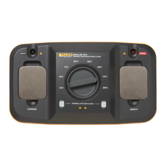
The Impulse 7010 Selectable Defibrillator Load
(hereafter the Load) provides multiple loads of
25, 50, 75, 100, 125, 150, 175, and 200 ohms for
testing defibrillators. In conjunction with an
Impulse 7000DP Defibrillator Analyzer (hereafter
the Analyzer), it is designed for performance
testing of defibrillators. It is not intended to be
used for calibration of medical equipment.
XW Warning
To avoid possible electrical shock or
personal injury, follow these
guidelines:
• Use this instrument only in the
manner specified by the
manufacturer or the protection
provided may be impaired.
• Read the Instruction sheet before
operating the Load.
• Do not use the product if it operates
abnormally.
• Do not use the product in wet
locations, around explosive gases or
dust.
• Observe all precautions noted by the
Device Under Test (DUT) equipment
manufacturer when analyzing the
DUT.
• Use extreme caution when working
with voltages above 30 volts.
Table 1 lists the symbols found on the Load and
describes their meaning.
Table 2 shows the front-panel controls and
connectors of the Load.
PN 3255163 February 2008
©2008 Fluke Corporation. All rights reserved.
Selectable Defibrillator Load
Table 1. Symbols
Symbol
W
Important information; refer to manual.
Do not dispose of this product as unsorted
~
municipal waste. Go to Fluke's website for
recycling information.
Conforms to relevant Australian EMC
;
requirements
Conforms to relevant Canadian and US
)
standards
X
Hazardous voltage
P
Conforms to European Union directives
IEC Measurement Category I – CAT I
equipment designed to protect against
transients in equipment on circuits not
CAT I
directly connected to MAINS. Under no
circumstances should the terminals of the
Load be connected to any MAINS voltage.
Preparing for Operation
Connect the Load ouput connectors to the input
connectors of the Analyzer as shown in Figure 2.
As shown in Figure 1, the selectable resistors of
the Load are connected in series and/or parallel
with the load across the defib connectors of the
Analyzer. The various connection combinations
available through the rotary switch, provide eight
different loads for a defibrillator discharge.
Using the Load for Testing
To use the Load for a defibrillator test:
1. Select the desired defibrillator load by
moving the rotary switch to one of the eight
load settings.
2. Setup the Analyzer for use with the
selectable load by pressing Q and then
the More soft key. Then press Defib Load to
7010
Instruction Sheet
Description
1
Advertisement

Related Manuals for Fluke Biomedical 7010


Summary of Contents for Fluke Biomedical 7010
- Page 1 7010 Selectable Defibrillator Load Instruction Sheet Introduction Table 1. Symbols The Impulse 7010 Selectable Defibrillator Load Symbol Description (hereafter the Load) provides multiple loads of 25, 50, 75, 100, 125, 150, 175, and 200 ohms for Important information; refer to manual.
- Page 2 5. Discharge the defibrillator and read the results in the Analyzer’s display. When set to 50Ω, the Load is bypassed and the load inside the Analyzer is used for the Table 2. Impluse 7010 Front-Panel Controls and Connectors feo003.eps Item Description...
- Page 3 50 Ω 275 V MAX 50 Ω DEFIBRILLATOR 5000 Vp MAX 50 Ω 50 Ω Defibrillator Under Test feo001.eps Firgure 1. Impulse 7010 Load Schematic Fluke Biomedical Fluke Biomedical Impulse 7000DP Impulse 7000DP Fluke Biomedical Fluke Biomedical Impulse 7010 Impulse 7010...
- Page 4 Selectable Defibrillator Load General Specifications General Specifications Maximum Voltage ..........5000 V Maximum continuous power ....... 12 W, equivalent to 10 defib pulses of 360 J every 5 minutes. Inductance............. < 2 μH, @25 Ω < 3 μH, @50 Ω <...
- Page 5 Cleaning the Analyzer W Caution Do not pour fluid onto the Load surface; fluid seepage into the electrical circuitry may cause the Load to fail. W Caution Do not use spray cleaners on the Load; such action may force cleaning fluid into the Load and damage electronic components.
Need help?
Do you have a question about the 7010 and is the answer not in the manual?
Questions and answers