
Subscribe to Our Youtube Channel
Related Manuals for DeDietrich DTGE130-35 Eco.NOxPlus


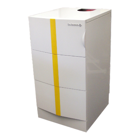
Summary of Contents for DeDietrich DTGE130-35 Eco.NOxPlus
- Page 1 ELIDENS Gas fired condensing boiler DTG(E)130 - 35/45/65/90/115 Eco.NOxPlus Technical instructions 300014279-001-J...
- Page 2 Declaration of conformity The appliance complies with the standard model described in declaration of compliance . It is manufactured and distributed pursuant to the requirements of european directives. The original of the declaration of compliance is available from the manufacturer. DTG(E)130 - 35/45/65/90/115 Eco.NOxPlus 15/02/2011 - 300014279-001-J...
-
Page 3: Table Of Contents
Contents Introduction ................5 Used symbols . - Page 4 8.4.2 Lengths of the air/flue gas pipes ..............34 Electrical connection.
-
Page 5: Introduction
1. Introduction 1 Introduction 1.1 Used symbols Caution danger Reference Risk of injury and damage to equipment. Attention must be Refer to another manual or other pages in this instruction paid to the warnings on safety of persons and equipment manual Important information Information must be kept in mind to maintain comfort... -
Page 6: Important Recommendations
2. Important recommendations 2 Important recommendations For a proper operating of the boiler, follow carefully the instructions. Any intervention on the appliance and heating equipment must be carried out by a qualified engineer. The manufacturer is not liable for any improper use of the appliance or failure to maintain or install the unit correctly (the user shall take care to ensure that the system is installed by a qualified engineer). -
Page 7: Description
3. Description 3 Description 3.1 General DTG(E)130 - 35/45/65/90/115 Eco.NOxPlus boiler are floor-standing They are designed for closed circuit hot water boiler rooms with a gas-fired condensing boilers fitted with a DIEMATIC3 conversational maximum operating temperature of 90°C. Their installation is control unit. - Page 8 3. Description Belgium The appliances comply with the requirements and standards laid down in the Royal Decree of 8 January 2004 and in the 17 July 2009. Installation and maintenance of the boiler must be carried out by a qualified professional in compliance with prevailing local and national regulations.
-
Page 9: Gas Categories
3. Description 3.3.2 Gas categories Supply pressure User country Gas category Gas type Minimum Maximum Natural gas H (G20) 17 mbar 25 mbar 2Esi3P Natural gas L (G25) 20 mbar 30 mbar Propane (G31) 25 mbar 57.5 mbar ES, IT Natural gas H (G20) 17 mbar 25 mbar... -
Page 10: Main Parts
3. Description 3.4 Main parts • DTGE130-35 • DTG130-35 / DTG130-45 / DTG130-65 Burner Fan air inlet Output sensor Return sensor 10 Ignition electrode + Ionization electrode Heating body 11 Flame inspection window Venturi premix 12 Inspection hatch Combined venturi and gas valve unit 13 Expansion vessel 14 Shunt pump (only for DTGE130-35) Control panel... - Page 11 3. Description • DTG130-90 / DTG130-115 Fan air inlet Return sensor Heating body Venturi premix Combined venturi and gas valve unit Control panel Burner Output sensor 10 Ignition electrode + Ionization electrode 11 Flame inspection window 12 Inspection hatch 15/02/2011 - 300014279-001-J DTG(E)130 - 35/45/65/90/115 Eco.NOxPlus...
-
Page 12: Technical Characteristics
3. Description 3.5 Technical characteristics 3.5.1 Boiler - For operation on Natural Gas or Propane (See "Switching from - Single-unit heat exchanger in aluminium/silicium alloy Natural Gas to Propane") - Cylindrical premix burner covered in metal fibres - The boiler is preset in the factory to operate on natural gas G20, - Centrifugal fan with combustive air intake silencer for a low noise Wobbe index IWS = 15.0 kWh/m , 20 mbar... -
Page 13: Technical Data
3. Description 3.6 Technical data DTG... 130... DTGE 35 DTG 35 DTG 45 DTG 65 DTG 90 DTG 115 CE identification no **** CE-0063BS3826 Boiler specifications Power input (Hi) - minimum/maximum G20 8.2 - 33.5 8.2 - 33.5 8.2 - 41.2 12.2 - 62.0 14.6 - 86.0 17.2 - 110.2... - Page 14 3. Description DTG... 130... DTGE 35 DTG 35 DTG 45 DTG 65 DTG 90 DTG 115 Connecting (diameter - Male) 1" 1" 1/4 1" 1/4 1" 1/4 1" 1/4 1" 1/4 Condensation water pH Condensation water run-off (diameter) Electrical specifications Electrical connection V/Hz 230/50...
-
Page 15: Main Dimensions
3. Description 3.7 Main dimensions 3.7.1 Boiler self-standing • DTGE130-35 Eco.NOxPlus DTGE130-35 Heating flow Flow to the exchanger on the independent DHW tank (plugged as standard) (Option) - Package HE25 or Package EA124 3 + 4 Flow and return for:... - Page 16 3. Description • DTG130-35 / 45 / 65 / 90 / 115 Eco.NOxPlus DTG130- 35 / 45 / 65 / 90 / 115 Heating flow Flow to the exchanger on the independent DHW tank (plugged as standard) (Option) - Package HE25 or Package EA124 Heating return Condensates discharge Ø...
- Page 17 DTG130-35 Eco.NOxPlus + Tank (BA150 l) - Boiler/tank connection kit (Package EA122) • DTGE130-35 Eco.NOxPlus + Tank (BA150 l) - Boiler/tank connection kit (Package EA124) • DTG130-35 Eco.NOxPlus + Tank BC or BP (150,200,300 l) - Boiler/tank connection kit (Package EA116) Connection options (Not represented): - DTGE130-35 Eco.NOxPlus + Tank BC or BP (150,200,300 l) -...
- Page 18 3. Description DTGE130- 35 DTG130- 35 / 45 / 65 / 90 / 115 Heating flow R 1 1/4 Flow to the exchanger on the independent DHW tank (plugged as standard) (Option) - Package HE25 or Package EA124 Heating return R 1 1/4 Automatic air vent Gas inlet...
-
Page 19: Boiler Installed
- 40 cm above the boiler • DTG(E)130- 35 / DTG130-45 / DTG130-65 / DTG130-90 / DTG130-115 Eco.NOxPlus • DTGE130-35 Eco.NOxPlus + Tank (150 litres) A. DTG(E)130- 35 / DTG130-45 / DTG130-65 = 1100 DTG130-90 / DTG130-115 = 1322 15/02/2011 - 300014279-001-J... -
Page 20: Hydraulic Specifications
3. Description 3.8 Hydraulic specifications Depending on the flow, the following diagrams represent: For a fixed flow, the manometric height available at the boiler outlet is obtained by taking the difference between the manometric height - the manometric heights of the heating circulator pumps (delivered of the circulator pump and the loss of load in the boiler. - Page 21 3. Description Optional 3-speed circulator pump for DTG130-45 - Package HC141 A. Rated net head (mWG) B. Flow rate (m C. Loss of load DTG130-45 Optional 3-speed circulator pump for DTG130-65 - Package HC143 A. Rated net head (mWG) B. Flow rate (m C.
-
Page 22: Control Panel
4. Control panel 4 Control panel 4.1 Electromechanical components The panel must always be supplied with 230V voltage: Main ON/OFF switch - to ensure the anti-grip of the heating pump. Pressure gauge Use the mode: * Depending on the model of the appliance, the pressure gauge is - "summer"... -
Page 23: Keys Accessible When The Flap Is Closed
4. Control panel 4.3 Keys accessible when the flap is closed Forced Low mode: Setting the temperatures - until midnight if flashes Comfort temperature - all the time if is steady Antifreeze mode Reduced temperature Tank load enabled mode: Domestic hot water temperature - until midnight if flashes - all the time if... -
Page 24: Operating Mode
4. Control panel 4.5 Operating mode Select the operating modes using the AUTO - • = Reduced mode keys. Heating operates according to the reduced temperature, • AUTO key = Automatic mode independently of the time programmes. Heating and domestic hot water production operate according to the time •... -
Page 25: Summer Mode
4. Control panel Anti-freeze Temporary activation (Number of days) Permanent activation First brief touch: Key Long touch, 5 seconds: Key For all circuits: With DIEMATIC Set the number of days' absence (current day = 1) using The arrow above the key is steady. keys (up to 99 days). -
Page 26: Heating And Domestic Hot Water Temperature Setting
5. Heating and domestic hot water temperature setting 5 Heating and domestic hot water temperature setting Comfort temperature Reduced temperature Domestic hot water temperature 5.1 Heating temperature setting The comfort and reduced temperatures are set separately for each circuit: Temperature Adjustment range Factory setting - Select the comfort temperature or the reduced temperature for the... -
Page 27: Selecting A Programme
6. Selecting a programme 6 Selecting a programme 6.1 Selecting a programme • The DIEMATIC 3 control unit includes 4 heating • Allocation of a programme to a circuit: programmes: - Select the circuit using key A.B.C. - 1 fixed programme P1, activated in the factory. - Select the programme using the PROG key. -
Page 28: Installation
7. Installation 7 Installation 7.1 Statutory terms and conditions of installation and maintenance Germany The installation and maintenance of the appliance must be carried out by a qualified professional in compliance with the statutory texts In addition to the instructions on construction and combustion of the codes of conduct in force, particularly: equipment, also abide by the following standards, rules and France... -
Page 29: Important Comments On The Treatment Of The Heating Circuit
7. Installation 7.3 Important comments on the treatment of the heating circuit Central heating systems must be cleaned to eliminate - 350 l/h for DTG130-115. debris (copper, strands, brazing flux) linked to the installation of the system and deposits that can cause In the event of run-off noise malfunctions (noise in the system, chemical reaction between metals). - Page 30 7. Installation Location DTG(E)130 - 35/45/65/90/115 Eco.NOxPlus boilers must be installed in a frost-free room. In order to avoid damage to the boiler, it is necessary to prevent the contamination of combustion air by chlorine and/or fluoride compounds, which are particularly corrosive.
-
Page 31: Connecting The Furnace
8. Connecting the furnace 8 Connecting the furnace These actions must be carried out by a qualified To prevent damage caused by overpressure on the gas regulator, the technician. gas supply valve must be closed before carrying out the pressure test on the gas supply pipe. -
Page 32: Flue Gas System Connections
8. Connecting the furnace 8.4 Flue gas system connections - The horizontal sections on the flue gas side will be constructed with The parts of this sheath which can be dismantled must allow for a gradient to the boiler of 3 %. The cross-section of the aeration inspection of the flue gas conduit along its entire length. -
Page 33: Classification
8. Connecting the furnace 8.4.1 Classification 3 3 3 Belgium: Boilers can only be installed with flue gas connection pipes Homologation C Air/flue gas connection by means of concentric provided by the constructor. For the list of parts, refer to the current price list. -
Page 34: Lengths Of The Air/Flue Gas Pipes
8. Connecting the furnace 8.4.2 Lengths of the air/flue gas pipes Lmax is measured by adding the lengths of the air/flue gas pipes and the equivalent lengths of the other elements. Maximum length of the connection pipes (metre) Type of air/flue gas connection Diameter DTGE130-35 DTG130-35 DTG130-45... -
Page 35: Electrical Connection
8. Connecting the furnace 8.5 Electrical connection The appliance must be powered by a circuit containing an omnipolar switch with an opening distance 3 mm. 12 Flow sensor (circuit B) 3-way valve (circuit C) 13 Input 0-10 V Pump (circuit C) 14 Room sensor (circuit B) Safety thermostat (circuit C) 15 Room sensor (circuit A) -
Page 36: Commissioning
9. Commissioning 9 Commissioning Initial commissioning must be done by a qualified Operation while the condensation water siphon is empty may professional. damage the boiler. Before start-up, the heating installation must be completely emptied and rinsed. 9.1 Filling the system Fill the installation with water. -
Page 37: Putting The Appliance Into Operation
9. Commissioning DTG (E) 35 DTG 45 DTG 65 DTG 90 DTG 115 DTG... 130... P min P nom P max P min P nom P max P min P nom P max P min P nom P max P min P nom P max Propane (50 mbar) - Page 38 9. Commissioning 9.3.1 DTGE130-35 / DTG130-35 / DTG130-45 / DTG130-65 / DTG130-90 For Belgium: Any work on the gas block must be carried Open the panel flap. out by a factory technician (For example: SERV’élite). Press key simultaneously for 2 seconds. The boiler is preset in the factory to operate on natural gas Set the burner output using the + and - keys.
- Page 39 9. Commissioning All countries except Belgium: content (%) content (%) Boilers DTGE130 DTG130- DTG130- DTG130- DTG130- DTGE130 DTG130- DTG130- DTG130- DTG130- Natural gas H (G20) Natural gas L (G25) Propane 10.7 10.7 10.7 10.7 10.7 Correct the burner setting to ±0.3% CO ;...
- Page 40 9. Commissioning 9.3.2 DTG130-115 For Belgium: Any work on the gas block must be carried Maximum power of the burner (Factory setting in kW) out by a factory technician (For example: SERV’élite). Boilers DTG130-115 The boiler is preset in the factory to operate on natural gas G20 G20. Heating mode (100 %) (Hi / Hs) 110.2 / 122.3 The conversion from Natural Gas G20 to Natural Gas G25 requires...
- Page 41 9. Commissioning Switch on the electrical supply. Starting the burner up. The appliance must be powered by a circuit containing an omnipolar switch with an opening distance 3 mm. The earth connection shall comply with standard NF C 15 100. Take the boiler up to maximum power.
- Page 42 9. Commissioning Set the burner output to minimum using the - key. : Minimum output. Measure the CO or O level in the flue gases. If necessary: Modify the "min output" setting with the setting screw (The adjustment screw is protected by a plug, Torx type screw and plug).
-
Page 43: Adapting The Output
9. Commissioning 9.4 Adapting the output Setting the burner output Control value Output (kW) (Hi / Hs) DTGE130-35 DTG130-35 DTG130-45 DTG130-65 DTG130-90 DTG130-115 33.5 / 37.2 33.5 / 37.2 41.2 / 45.7 62.0 / 68.8 86.0 / 95.5 110.2 / 122.3 30.8 / 34.2 30.8 / 34.2 37.9 / 42.1... -
Page 44: Messages - Alarms
10. Messages - Alarms 10 Messages - Alarms 10.1 Faults In the event of a fault, the display may show the following messages. Contact your fitter. Message Probable causes Action The message SHOW REM.CTRL To cancel the overrides on all remote controls, press the AUTO key for 5 seconds. SHOW REM. - Page 45 10. Messages - Alarms Faults Probable causes Action FAN OFF FAIL The fan is not working Fan defective Check the fan wiring (corrosion of the connection) Safety control box defective FAN ON FAIL The fan is working constantly Electrical connections broken Fan control is defective (replace the fan) BOILER S.FAIL.
-
Page 46: Blockage (Temporary)
10. Messages - Alarms 10.2 Blockage (temporary) Code no. Description Checks BL. AIR The setting of the parameters is incorrect Check the boiler type Briefly cut the electrical power supply to the boiler using the On/Off switch Check the wiring BL.RET.HIGH.BOI Return temperature >... -
Page 47: 11 "User" Settings
11. "User" settings 11 "User" settings Key for access to setting and measurements Page scrolling Line scrolling Back to the title or the previous line Programming keys Enter (per 1/2 hour) the comfort temperature period or tank load enabled (dark area) Enter (per 1/2 hour) the reduced temperature period or tank load disabled (light area) Return key 11.1 Measurements... -
Page 48: Programming
11. "User" settings 11.2 Programming Factory programmes See chapter Selecting a programme Resetting the programmes Press the STANDARD key for 5 seconds. All customised programmes are replaced with their factory setting. Programme P1 is assigned to all heating circuits. Customised programming #PROG. - Page 49 11. "User" settings #PROG. DHW: Domestic hot water #PROG. AUXIL: Programming the auxiliary outlet Filling enabled Authorised operation Monday Monday Tuesday Tuesday Wednesday Wednesday Thursday Thursday Friday Friday Saturday Saturday Sunday Sunday Press Display Parameter set Factory setting #PROG. CIRC.A * Heating programme for circuit A if used PROG EVERY DAY P2 PROG MONDAY P2...
- Page 50 11. "User" settings Press Display Parameter set Factory setting #PROG. DHW * 5:00 - 22:00 PROG EVERY DAY PROG MONDAY PROG TUESDAY then PROG WEDNESDAY PROG THURSDAY PROG FRIDAY PROG SATURDAY PROG SUNDAY #PROG. AUXIL * 6:00 - 22:00 PROG EVERY DAY PROG MONDAY PROG TUESDAY then...
-
Page 51: Adjustment
11. "User" settings 11.3 Adjustment Adjustment Press Display Parameter set Factory setting Customer setting range #SETTING The parameters are set using keys CONTRAST DISP. Allows the display contrast to be set using keys BACK LIGHT ON Lighting is permanent if the circuit is on comfort period If the circuit displayed is in a reduced period, the light shows ECO... - Page 52 11. "User" settings SUM/WIN Used to set the outside temperature above which heating will be shut down. - The heating pumps are shut down, - The burner will only start for domestic hot water needs, - The symbol E appears. If this parameter is set to NO, heating will never be shut down automatically.
-
Page 53: Clock Settings
11. "User" settings 11.4 Clock settings Adjustment Press Display Parameter set Factory setting Customer setting range #TIME . DAY The parameters are set using keys HOURS MINUTE MONTH then DATE YEAR SUM. TIME: AUTO: automatic switch to summer time on the last Sunday in March and back to winter time on the last AUTO Sunday in October. -
Page 54: Installer Settings
12. Installer settings 12 Installer settings These actions must be carried out by a qualified The various settings and programmes are saved even when the technician. power supply is cut off. Open the flap surrounding the display. Press on the installer key for 5 seconds using a screwdriver or a To return to the factory settings of parameters (user and fitter point of a pencil. -
Page 55: Professional" Settings
12. Installer settings 12.1 "Professional" settings Adjustment Press Display Parameter set Factory setting range #LANGUAGE Language selection using keys seconds then FRANCAIS FRANCAIS then #LIMITED TEMP. Setting the temperature limits using keys BOILER MAX Maximum boiler temperature and boiler setting if 80 °C 30 to 90 °C producing domestic hot water... - Page 56 12. Installer settings BCT (Bottom of Curve temperature) Used to impose a minimum temperature on the boiler circuit. To direct/control the boiler at a constant temperature by HCZP, set circuit gradient A/B to 0. This setting is required to control an aerothermal or pool type circuit.
-
Page 57: Settings Relating To A Heating Circuit
12. Installer settings 12.2 Settings relating to a heating circuit Factory Adjustment Customer Press Display Parameter set setting range setting #FITTER PARAM. Setting parameters specific to the installation using keys then BUILD. INERTIA Characterisation of building's inertia 3 (22 hours) 0 (10 hours) to 10 (50 hours) CIRC.CURVE A * Gradient in circuit A... - Page 58 12. Installer settings BUILD. INERTIA CIRC. CURVE ... Modification of the factory setting is only useful in exceptional Independent setting for each circuit. cases. - Heating curve circuit A 0 for a building with low thermal inertia. 3 for a building with normal thermal inertia. 10 for a building with high thermal inertia.
- Page 59 12. Installer settings 12.2 Settings relating to a heating circuit (continued) Adjustment Customer Press Display Parameter set Factory setting range setting #FITTER PARAM. Setting parameters specific to the installation using keys then CT.TEL: OPEN Telephone input activates if the contact is open OPEN CLOSE CLOSE...
- Page 60 12. Installer settings KT.TEL: setting OPEN CLOSE OPEN CLOSE I.TEL: status OPEN CLOSE CLOSE OPEN I.TEL: ANTIFR Boiler Antifreeze Antifreeze mode Boiler operating mode operating mode selected mode selected DHW+HEAT Hot water storage Burner, heating load pump Boiler operating mode selected. tank affected to (auxiliary pump) and DHW load heating and...
- Page 61 12. Installer settings CT.TEL: 0-10 V function Defines the nature of the contact (open or closed) which This function controls the boiler using an external system that activates the function associated with the telephone input. includes a 0-10 V output connected to the 0-10 V input. This control imposes an instruction set temperature on the boiler.
-
Page 62: Miscellaneous
12. Installer settings 12.3 Miscellaneous Adjustment Customer Press Display Parameter set Factory setting range setting #MISCELLANEOUS The parameters are set using keys then ALTERNATED Alternate display of the two preceding displays ALTERNATED TIME - DAY Permanent time display ALTERNATED TIME - DAY BOILER. -
Page 63: Parameter And Input/Output Check (Mode Tests)
12. Installer settings 12.4 Parameter and input/output check (mode tests) Press Display Output or input parameter status #PARAMETERS 10 seconds then PERMUT Cascade permutation status (1 = permutation 1-2, 2 = permutation 2-1) STAGE Current speed (Number of boilers requesting heating) NB.CASC.: Number of boilers recognised in the cascade POWER %... - Page 64 12. Installer settings Press Display Output or input parameter status #TEST INPUTS then PHONE REM. Bridge on telephone input (1 = presence, 2 = absence) FLAME Flame (1 = presence, 2 = absence) FAILURE Fault display: yes (1) or no (0) SEQ.
-
Page 65: Adapting To Another Gas Type
13. Adapting to another gas type 13 Adapting to another gas type For Belgium: Only SERV’élite is authorised to carry out the The boiler installation and gas connection must be carried conversion of this appliance. out by a qualified professional in compliance with the NBN D 51.003, NBN D 30.003, NBN B 61.001, NBN B 61.002 and NBN D 51.006 standards. - Page 66 13. Adapting to another gas type Switch the On/Off switch on Off. Preset the burner by turning the "max output" setting screw - by 3 turns to the right: DTGE130-35, DTG130-35, DTG130-45. - by 4 turns to the right: DTG130-65. Install the conversion kit on DTG130-90.
- Page 67 13. Adapting to another gas type DTG130-115 Changing from Natural Gas to Propane requires: - Installing the conversion kit. Place the stop/start switch on On. Set the maximum fan speed to a value of: - 6700 rpm: DTG130-115. See chapter Parameter and input/output check (mode tests) "Table: MAX.VENT."...
-
Page 68: Gas Type
13. Adapting to another gas type Modify the "min output" setting with the setting screw Check the output delivered again. See Table page 40. Adjust if necessary. For Switzerland: The maximum limit values authorised by the OPAIR federal order on air protection regarding CO and NOx must be checked using measurements made in the place of installation. -
Page 69: Filling In The Commissioning Certificate
14. Filling in the commissioning certificate 14 Filling in the commissioning certificate Please tick off the work carried out and write down the measurement values Date Company Installation Carry out a gas tightness check Check the fresh air / flue gas pipe Check the tightness of the flue gas pipe Check the neutralisation equipment if used Compare the information on the appliance's rating plate with the type of gas available in situ... -
Page 70: Maintenance
15. Maintenance 15 Maintenance 15.1 General The boiler requires little maintenance if it is correctly set. The boiler only requires an annual check and cleaning if necessary. 15.2 Inspection The annual inspection of the boiler can be restricted to the following - Set the gap between the ignition electrodes: 3 to 4 mm operations: - Check the concentric flue gas evacuation and combustive air inlet... -
Page 71: Setting The Ignition Electrode
15. Maintenance 15.2.2 Setting the ignition electrode - Check the setting of the ignition electrode. Set the gap between the ignition electrodes: 3 to 4 mm. 15.2.3 Checking the hydraulic pressure The hydraulic pressure must be a minimum of 0.8 bars. We recommend filling the installation to around 1.5 bars higher than the static height. -
Page 72: Cleaning And Maintenance
15. Maintenance 15.3 Cleaning and maintenance Before any operation, ensure that: - The gas supply is shut off, - The mains supply is disconnected, - The boiler is hydraulically isolated and drained (if required). DTG(E)130 - 35/45/65/90/115 Eco.NOxPlus 15/02/2011 - 300014279-001-J... - Page 73 15. Maintenance Operational mode When the boiler is fouled, carry out the following maintenance - Clean the fan, operations: - Clean the siphon, - Close the heating body, - Open the heating body, - Measure the combustion. - Clean the burner, - Clean the heat exchanger using the tool provided, Opening and closing the heating body Remove the inspection hatch, fan, burner and gas block unit.
- Page 74 15. Maintenance Cleaning the heat exchanger Cleaning the siphon Specific tools: Cleaning knife See chapter Spare parts DTGE130-35, DTG130-35, DTG130-45, DTG130-65: Ref. 83 DTG130-90: Ref. 283 DTG130-115: Ref. 483 Clean inside the exchanger using the specific knife. Remove the residues from the bottom of the exchanger. DTG(E)130-35/45/65: Unscrew the nut on the siphon from underneath the boiler Rinse with water jet until the water in the siphon runs clean.
-
Page 75: Maintenance Of The Air/Flue Gas Drain Connection Flues
15. Maintenance 15.4 Maintenance of the air/flue gas drain connection flues The connection pipes must be serviced at least once a year. - Check the seal. - Check the condensates evacuation device in the boiler and on the - Check that the pipe and the terminal are empty along their entire pipe if used. -
Page 76: Chimney Sweep Instructions
16. Chimney sweep instructions 16 Chimney sweep instructions Setting the boiler output for measuring emissions Tilt the flap on the control panel. EMISSION MES. 88.8°: Boiler temperature EMISSION MES. 8888: Fan speed Press key simultaneously for 2 seconds. EMISSION MES. 88.8uA: Ionization current Use keys + and - to switch from : Maximum boiler output : Minimum output... -
Page 77: Schematic Diagrams
17. Schematic diagrams 17 Schematic diagrams Safety box Operation Display (Not used) Fuse Protection Function protected Ignitor + Ionization probe 230 Volt 2 AF (quick) Safety box Transformer 24 Volt 4 AT (slow) Fuse Safety box 6.3 AT (slow) Power supply 15/02/2011 - 300014279-001-J DTG(E)130 - 35/45/65/90/115 Eco.NOxPlus... - Page 78 17. Schematic diagrams Electrical principle diagram See next page. DTG(E)130 - 35/45/65/90/115 Eco.NOxPlus 15/02/2011 - 300014279-001-J...
- Page 79 17. Schematic diagrams Legend: 0-10 V Input Alim 230 V 50 Power supply230 V - 50 Hz Heating pump circuit A DHW pump Auxiliary pump BPR - BPR I Burner reset button Safety contact EMI-supressor filter PCB connector Lane MCBA Safety box Neutral RL PA...
-
Page 80: Spare Parts
18 Spare parts 15/02/2011- 300014279-002-H To order a spare part, give the reference number shown on the list. Boiler body DTG(E)130 - 35/45/65 Eco.NOxPlus DE DIETRICH THERMIQUE S.A.S. - Spare parts centre 4 rue d’Oberbronn - F-67110 REICHSHOFFEN - +33 (0)3 88 80 26 50 - +33 (0)3 88 80 26 98 dedietrichthermique.com... - Page 81 18. Spare parts Casing DTG(E)130 - 35/45/65 Eco.NOxPlus 15/02/2011 - 300014279-001-J DTG(E)130 - 35/45/65/90/115 Eco.NOxPlus...
- Page 82 18. Spare parts Boiler body DTG130 - 90 Eco.NOxPlus 229 266 279 250 DTG(E)130 - 35/45/65/90/115 Eco.NOxPlus 15/02/2011 - 300014279-001-J...
- Page 83 18. Spare parts Casing DTG130 - 90 Eco.NOxPlus 15/02/2011 - 300014279-001-J DTG(E)130 - 35/45/65/90/115 Eco.NOxPlus...
- Page 84 18. Spare parts Boiler body DTG130 - 115 Eco.NOxPlus 479 450 DTG(E)130 - 35/45/65/90/115 Eco.NOxPlus 15/02/2011 - 300014279-001-J...
- Page 85 18. Spare parts Casing DTG130 - 115 Eco.NOxPlus 15/02/2011 - 300014279-001-J DTG(E)130 - 35/45/65/90/115 Eco.NOxPlus...
- Page 86 18. Spare parts Mark. Reference Description Mark. Reference Description 300013085 Multiple flow pipe DTGE130-35 Boiler body DTG(E) 35 / DTG45 / DTG65 Eco.NOxPlus 300013105 Gasket box pipe Complete leak proof box 97550181 Neoprene gasket diameter 44x32x2 mm 200010110 DTGE130-35 54798 Hinge pin Leak proof box 200009362...
- Page 87 18. Spare parts Mark. Reference Description Mark. Reference Description 200010252 Power supply harness S55994 Flue gas discharge pipe DN 100 200010251 Burner harness S57163 Measurement device cap 200010212 cable form 230 V S54763 Adapter cover DN 100 200010211 cable form 24 V 54781 Complete adapter DN 100/150 S54761...
- Page 88 18. Spare parts Mark. Reference Description Mark. Reference Description 57827 Right flange gas block 95362450 Outside sensor AF 60 S100363 Gas valve flange gasket 33x2 300013123 Sheeting 26 pts lg. 610 200009275 Card supports 300013129 Sheeting 14,MCBA pts length 1650 200009276 Board guard 52484...
- Page 89 18. Spare parts Mark. Reference Description Mark. Reference Description S100052 Screw M4x10 200009281 Control panel guard S100051 Stud M5x15 S100045 Air silencer S48512 Screw M5x10 S6778 Fuse 6.3 AT (slow) Power supply S100054 Screw M5x16 S14510 Fuse 4AT (slow) 24 V MCBA S14342 Screw M5x12 S43563...
- Page 90 18. Spare parts Mark. Reference Description Casing DTG130-115 Eco.NOxPlus 200009374 Complete top panel 200010105 Complete left panel 200010104 Complete right panel 200009285 Panel cover 200009376 Complete flap 300012374 Hinge 94820110 Catch 94820120 200009377 Complete front panel 200010107 Complete lower front panel DTG(E)130 - 35/45/65/90/115 Eco.NOxPlus 15/02/2011 - 300014279-001-J...
- Page 91 18. Spare parts 15/02/2011 - 300014279-001-J DTG(E)130 - 35/45/65/90/115 Eco.NOxPlus...
- Page 92 © Copyright All technical and technological information contained in these technical instructions, as well as any drawings and technical descriptions supplied, remain our property and shall not be multiplied without our prior consent in writing. Subject to alterations. 15/02/2011 DE DIETRICH THERMIQUE 57, rue de la Gare F- 67580 MERTZWILLER - BP 30...
Need help?
Do you have a question about the DTGE130-35 Eco.NOxPlus and is the answer not in the manual?
Questions and answers