
Related Manuals for DeDietrich Elitec DTG 1304 Eco.NOx/V


Summary of Contents for DeDietrich Elitec DTG 1304 Eco.NOx/V
- Page 1 Elitec DTG 1300 Eco.NOx/V English Gas-fired boilers 23/06/05 Technical instructions...
-
Page 2: Table Of Contents
Contents Compliance................. .3 Introduction . -
Page 3: Compliance
Declaration of compliance Declaration of compliance A.R. 8/1/2004 - BE Manufacturer DE DIETRICH THERMIQUE S.A.S. 57 rue de la gare F-67580 MERTZWILLER +33 3 88 80 27 00 +33 3 88 80 27 99 Issued by See end of notice We hereby certify that the range of equipment specified below is in accordance with the format stated in the EC declaration of comformity, that it is manufactured and distributed in accordance with the regulations and requirements in European Directives and with the regulations and requirements defined in the Royal Decree dated 8th January 2004.:... -
Page 4: Introduction
Introduction 1 Important recommendations For a proper operating of the boiler, follow carefully the Check that the equipment is properly set for the type of gas instructions. used. Any intervention on the appliance and heating equipment Keep to the polarity shown on the terminals : phase (L), must be carried out by a qualified technician. -
Page 5: Symbols Used
3 Symbols used Symbols used Risk of injury and damage to equipment. Caution danger Attention must be paid to the warnings on safety of persons and equipment. Information must be kept in mind to maintain Specific information comfort. Refer to another manual or other pages in this Reference instruction manual. -
Page 6: Description
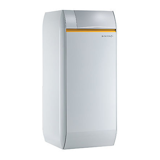
Description 1 Introduction The ELITEC DTG 1300 Eco.NOx/V boiler is a floor-standing cast The boilers are equipped with an anti smoke release safety device ; iron gas-fired boiler with an atmospheric burner with very low they may therefore be installed in inhabited areas. It consists of a pollutant emission with integrated domestic hot water production. -
Page 7: Main Parts
User country User country Gas category Gas type Connection pressure (mbar) 2ESi3P ES, PT, IE, CH, GB, DK, CZ, GR 2H3P 30/37 IT, SE, NO, FI, IS 2H3P 2ELL3P 2L3P 2E3P G25.1 2ES3P 30/50 4 Main parts Gas regulation block: It has a progressive opening, regulation valve and safety valve in series which is controlled by the boiler adjustment dial. -
Page 8: Technical Characteristics
5 Technical characteristics DTG ... Eco.NOx 1304 1305 1306 Nominal power Pn Power input 13,4 20,1 26,7 Gas flow rate 1,42 2,13 2,83 - Natural gas H (G20) 1,65 2,47 3,29 - Natural gas L (G25) - Propane (G31) kg/h 1,04 1,56 2,07... -
Page 9: Main Dimensions
6 Main dimensions Adjustable feet : basic sizes : 40 mm. Can be adjusted from 40 mm Hot water outlet R 3/4 (3/4") to 55 mm. All height dimensions are given with a feet setting of 40 Circulation R 3/4 (3/4") mm (see chapter Levelling). -
Page 10: Installation
Installation 1 Implementation The boiler can be installed : - in the kitchen, - in the cellar, - in the boiler house. 5 cm from the w It is necessary to have in every case : - 5 cm on one of the boiler sides, - 70 cm minimum in front, - and 5 at the rear. -
Page 11: Levelling
2 Levelling Levelling is done using the 4 feet located on the heater socket and using a flat screwdriver. Lift the tank slightly with a lever to adjust the feet. Adjustable feet : Basic dimension 40 mm. Can be adjusted from 40 mm to 55 mm. -
Page 12: Control Panel Assembly
Control panel assembly The command panel is attached as follows : 1. Unscrew the 2 mounting screws at the back of the column head. 2. Remove the upper casing of the boiler. 3. Unscrew the 2 mounting screws from the screen 4. - Page 13 7. Take out the heater door. Keep the position of the contact spring with relation to the bulbs. 8. Place the bulbs in the sensor tube in front of the boiler. Push them Tighten the assembly before engaging the glove finger. into the funnel until it butts against it.
- Page 14 13. Attach the burner cable to the 12 connector studs located on the 16. Attach the anti-release safety device onto the 3 connector studs inner face of the command panel. on the command panel. 14. Connect the earth cable to the clip located on the front plate. Connect the panel's electrical connections according to the panel's instructions 15.
- Page 15 20. Screw the panel front onto the screen using a mounting screw. Re-assemble the door and the column head. 23/06/05 - 300002940-001B DTG 1300 Eco.NOx/V...
-
Page 16: Connecting The Furnace
Connecting the furnace 1 Hydraulic connections Installation must be carried out in accordance with the prevailing regulations, the codes of practice and the recommendations in these instructions. Important recommendations for connecting the boiler to the heating circuit There must be no total or partial closing mechanism In the event where the burner is located at the highest point in the between the boiler and the safety valves (France: DTU - installation, a dry running or water pressure control device my be... -
Page 17: Connecting To A Chimneye
3 Connecting to a chimneye The equipment must be installed following the codes of practice The pipe must be laid out to allow any likely condensation to drain. using sealed stainless steel, aluminium or internally meshed tubing It must be in accordance with existing regulations for pipes used for capable of withstanding hot combustion gases and any likely acid this purpose. -
Page 18: Adapting To Another Gas
Adapting to another gas Operations to be carried out to allow the change from H/E natural gas to L/LL natural gas or to propane and vice versa. Conversion kits The actions described below must be carried out by a Package GL34 qualified technician. -
Page 19: Setting The Injector Pressure
4 Setting the injector pressure Connect a manometer to the pressure socket located on the manifold. Remove the protective cover C on the regulator by unscrewing it using a screwdriver. Set the pressure on the injectors by moving the gas regulator on the valve. -
Page 20: Commissionning
Commissionning 1 Refilling the installation Firstly, fill the tank with domestic hot water. Unstick the load pump in necessary: to do this, unscrew the protection cap in front of the pump and insert a screwdriver into the Domestic hot water circuit slit (V) on the pump center line. -
Page 21: Commissionning
3 Commissionning The first start-up is to be performed by your installation - Create a requirement for heat. engineer. Please consult the document delivered with the command panel before carrying out any action with it. - Open the gas blocking tap. - Check that the safety thermostat has not triggered. -
Page 22: Checks And Adjustments After Commissioning
Operating cycle with the anti-smoke release thermostat cut Key : Start of operation Second ignition attempt Third ignition attempt Formation of flame in ignition burner End of first ignition attempt End of second ignition attempt On safety through absence of flame signal Smoke anti-release thermostat cut Resetting Restart of heater... - Page 23 Checking the anti-smoke release thermostat In the event of smoke release by the anti-blowback device, the anti- release safety device switches off the burner with the safety box on standby for 15 minutes (this is indicated by an alarm indicator flashing).
-
Page 24: Maintenance
Maintenance 1 Cleaning main burner and ignition burner The main burner and the ignition burner injector with its filter must be regularly cleaned to ensure good performance. Il est conseillé de le faire au moins 1 fois par an. - Re-assemble the burner earth wire Ignition burner Ionisation probe Ignition electrode... -
Page 25: Cleaning Heater Body
2 Cleaning heater body Sweep the heater. Take out the burner drawer from the heater body. Do not block the gas ramp openings. With the burner out : Take out the column head fixed by 2 screws and toothed washers Take out the insulation Open the sweeping trap by unscrewing the 2 screws Clean the heater body with the special brush delivered with the... - Page 26 - measure the strength of the current between the tank and the Descaling anode ; if the current measured is less than 0.1 mA, the anode In hard water regions, we recommend descaling the tank annually in should be replaced. order to maintain its performance.
-
Page 27: Incidents And Solutions
Incidents and solutions Symptoms Probable causes Solution The heater does not start - The heater thermostat - Create a demand by moving the heater thermostat or the setting level and the safety box is not requiring heat (option). affected (red alarm - Setting (option) is not requiring indicator off) - Page 28 Symptoms Probable causes Solution Heater too hot or too cold - 3 position switch on position - Check the position of the 3 position switch for requirements - Wrong setting for the heater - Set the heater thermostat if the heater has SV-matic setting or an ambient thermostat thermostat Flame returns...
- Page 29 To order a spare part, quote the reference number next to the part required. Domestic hot water tanks 23/06/05 - 300002940-001B DTG 1300 Eco.NOx/V...
-
Page 30: Spare Parts
Spare parts - DTG 1300 Eco.NOx/V 23/06/05 - 300002940-002A Boiler body + Draught diverter + Insulation DE DIETRICH THERMIQUE S.A.S. - Spare parts centre 4, rue d’Oberbronn - F-67110 REICHSHOFFEN - Tél. : (+33) 03 88 80 26 50 - Fax : (+33) 03 88 80 26 98 dedietrichthermique.com... - Page 31 Gas line Cladding 23/06/05 - 300002940-001B DTG 1300 Eco.NOx/V...
- Page 32 Linking kit DTG 1300 Eco.NOx/V 23/06/05 - 300002940-001B...
- Page 33 Code no. Description Code no. Description 200000095 Electric circuit - Anti-backflow thermostat Tank 8366-5501 Body screws packet + Draught diverter 8955-5509 LI130 foam for DTG 1304 and 1305 Eco.NOx/V 8955-5510 LI130 foam for DTG 1306 Eco.NOx/V Insulating material for body 8970-5511 7 mm seal kit 200000522...
- Page 34 Code no. Description Code no. Description Cladding 9536-2447 KVT sensor 8518-8631 Cladding - 4 sections 8575-4909 DHW connector 8518-8632 Cladding - 5 sections 8518-8633 Cladding - 6 sections 8518-8640 Front plate - 4 sections 8518-8641 Front plate - 5 sections 8518-8642 Front plate - 6 sections 8518-8530...
-
Page 35: Warranty
Warranty You have just purchased a DE DIETRICH appliance and we France thank you for the trust you have placed in our products. The preceding dispositions are not exclusive of benefits for the Please note that your appliance will provide good service for a purchaser of the legal guarantee as stated in Civil Code articles longer period of time if it is regularly checked and maintained. - Page 36 DTG 1300 Eco.NOx/V 23/06/05 - 300002940-001B...
- Page 37 DTG 1300 Eco.NOx/V 23/06/05 - 300002940-001B...
- Page 38 DTG 1300 Eco.NOx/V 23/06/05 - 300002940-001B...
- Page 39 DTG 1300 Eco.NOx/V 23/06/05 - 300002940-001B...
- Page 40 DE DIETRICH THERMIQUE S.A.S. DE DIETRICH HEIZTECHNIK www.dedietrich.com www.dedietrich.com Direction des Ventes France Am Concorde Park 1 - B 4 / 28 57, rue de la Gare A-2320 SCHWECHAT / WIEN F- 67580 MERTZWILLER +43 (0)1 / 706 40 60-0...
Need help?
Do you have a question about the Elitec DTG 1304 Eco.NOx/V and is the answer not in the manual?
Questions and answers