
Related Manuals for Eiki LC-WB200W


Summary of Contents for Eiki LC-WB200W
- Page 1 Multimedia Projector Network Supported Wired LAN Refer to the Owner's Manuals below MODEL LC-WB200 for details about network function. Network Set-up and Operation PJ Network Manager Owner's Manual...
-
Page 2: Features And Design
Features and Design This Multimedia Projector is designed with the most advanced technology for portability, durability, and ease of use. This projector utilizes built-in multimedia features, a palette of 16.77 million colors, and matrix liquid crystal display (LCD) technology. ♦ Compact Design ♦ Security Function This projector is designed compact in size The Security function helps you to ensure... -
Page 3: Table Of Contents
Table of Contents Features and Design . . . . . . . . . . . . . . 2 Computer System Selection Auto PC Adjustment Table of Contents . . . . . . . . . . . . . . . . . 3 Manual PC Adjustment To the Owner . -
Page 4: To The Owner
To the Owner Before installing and operating this projector, read this Safety Precaution manual thoroughly. This projector provides many convenient features and WARNING: functions. Operating the projector properly enables you to manage THIS APPARATUS MUST BE EARTHED. those features and maintains it in good condition TO REDUCE THE RISK OF FIRE OR for many years to come. Improper operation may ELECTRIC SHOCK, DO NOT EXPOSE result in not only shortening the product-life, but also THIS APPLIANCE TO RAIN OR MOISTURE. -
Page 5: Safety Instructions
Safety Instructions All the safety and operating instructions should be read This projector should be operated only from the type before the product is operated. of power source indicated on the marking label. If you are not sure of the type of power supplied, consult your Read all of the instructions given here and retain them authorized dealer or local power company. -
Page 6: Air Circulation
Safety Instructions Installing the Projector in Proper Air Circulation Position Openings in the cabinet are provided for Install the projector properly. Improper installation ventilation. To ensure reliable operation of the may reduce the lamp life and cause a fire hazard. product and to protect it from overheating, these openings must not be blocked or covered. -
Page 7: Compliance
Model Number : LC-WB200 Trade Name : EIKI Responsible party : EIKI International,Inc. Address : 30251 Esperanza Santa Margaria CA 92688-2123 Telephone No. : 800-242-3454 (949-457-0200) -
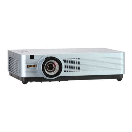
Page 8: Part Names And Functions
Part Names and Functions ① Infrared Remote Receiver Front ② Zoom Ring ③ Focus Ring ④ Projection Lens CAUTION Do not cover the light beam in front of the lens. High temperature from light beam may damage the lens. ⑤ Lens Cap (See page 62 for attaching.) ⑨... -
Page 9: Rear Terminal
Part Names and Functions Rear Terminal ⑤ ④ ① ③ ② ⑥ ⑩ ⑦ ⑪ ⑨ ⑧ ⑦ CONTROL PORT ① LAN Connection Terminal When controlling the projector with Connect the LAN cable (refer to the owner’s RS-232C, connect the control equipment manual of "Network Set-up and Operation"). to this connector with the serial control ②... -
Page 10: Top Control
Part Names and Functions Top Control ⑨ ⑤ ④ ⑧ ⑦ ③ ② ① ⑥ ① SELECT button ⑥ MENU button – Execute the selected item (p.21). Open or close the On-Screen Menu (p.21). – Expand or compress the image in the Digital zoom mode (p.35). ⑦... -
Page 11: Remote Control
Part Names and Functions Remote control ④ VIDEO button Select the VIDEO input source. (p.36) ① ⑤ S-VIDEO button Select the S-VIDEO input source. (p.36) ② ⑥ Point ▲▼◄► buttons – Select an item or adjust the value in the On-Screen Menu. (p.24) ㉒ – Pan the image in the Digital zoom +/- ③... -
Page 12: Remote Control Battery Installation
Part Names and Functions Remote control Battery Installation Open the battery Install new batteries Replace the compartment lid. into the compartment. compartment lid. Two AAA size batteries For correct polarity (+ and –), be sure battery terminals are in contact with pins in compartment. WARNING To ensure safe operation, please observe the following precautions : ● Use two (2) AAA or LR03 type alkaline batteries. -
Page 13: Installation
Installation Positioning the Projector For projector positioning, see the figures below. The projector should be set perpendicularly to the plane of the screen. Note: • The brightness in the room has a great influence on picture quality. It is recommended to limit ambient lighting in order to obtain the best image. • All measurements are approximate and may vary from the actual sizes. 40.6' (12.38 m) 25.2' (7.67 m) 16.8' (5.10 m) 12.5' (3.82 m) 8.3' (2.54 m) 2.4' (0.74 m) -
Page 14: Connecting To A Computer
Installation Connecting to a Computer Cables used for connection • VGA Cables (Mini D-sub 15 pin) * • Audio Cable • HDMI-DVI cable (*One cable is supplied; other cables are not supplied with the projector.) Monitor Input Monitor Output Monitor Output Audio Output External Audio Equipment HDMI- Audio Input cable cable cable cable Audio cable This terminal is switchable. -
Page 15: Connecting To Video Equipment
Installation Connecting to Video Equipment Cables used for connection • Video and Audio Cable (RCA x 3) • S-VIDEO Cable • Audio Cable • HDMI Cable (Cables are not supplied with the projector. ) External Audio Equipment Video and Audio Output Audio Input (Video) S-Video Output Video and Audio cable S-Video cable HDMI cable audio cable (stereo) AUDIO IN AUDIO OUT (stereo) VIDEO HDMI... -
Page 16: Connecting To Component Video And Rgb (Scart) Equipment
Installation Connecting to Component Video and RGB (Scart) Equipment Cables used for connection • Audio Cables • Scart-VGA Cable • VGA Cable • Component Cable • Component-VGA Cable (Cables are not supplied with this projector.) External Audio Equipment RGB Scart Component Video Output Audio Output Monitor Input 21-pin Output (Y, Pb/Cb, Pr/Cr) Audio Input Component cable Scart-VGA Audio cable cable cable (stereo) Component-... -
Page 17: Connecting The Ac Power Cord
Installation Connecting the AC Power Cord This projector uses nominal input voltages of 100-240 V AC and it automatically selects the correct input voltage. It is designed to work with single-phase power systems having a grounded neutral conductor. To reduce the risk of electrical shock, do not plug into any other type of power system. -
Page 18: Basic Operation
Connect the projector’s AC power cord into an AC outlet. The POWER indicator lights red. Open the lens cap. http://www.eiki.com Press the ON/STAND-BY button on the The preparation display will disappear after 30 top control or on the remote control. - Page 19 Basic Operation Enter a PIN code Use the Point ▲▼ buttons to enter a number. PIN Code Input Dialog Box Press the Point ► button to fix the number and move the red frame pointer to the next box. The number changes to . If you fixed an incorrect number, use the Point ◄...
-
Page 20: Turning Off The Projector
Basic Operation Turning Off the Projector Press the ON/STAND-BY button on the top control or on the remote control, and Power off? appears on the screen. Press the ON/STAND-BY button again to turn off the projector. The POWER indicator starts to blink red, and the cooling fans keep running. -
Page 21: How To Operate The On-Screen Menu
Basic Operation How to Operate the On-Screen Menu The projector can be adjusted or set via Top Control the On-Screen Menu. The menus have a hierarchical structure, with a main menu that is divided into submenus, which are further divided into other submenus. For each adjustment and POINT ▲▼◄►... -
Page 22: Main Menu
Basic Operation Main Menu For detailed functions of each menu, see “Menu Tree” on pages 68-69. Main Menu Sub-Menu ① ② ③ ④ ⑤ ⑥ ⑦ ⑧ ⑨ ⑩ ① Input Used to select an input source from Computer 1, Computer 2, HDMI, Video or S-video. (pp.27, ②... -
Page 23: Zoom And Focus Adjustment
Basic Operation Zoom and Focus Adjustment Rotate the Zoom Ring to zoom in and out. Rotate the Focus Ring to adjust the focus of Focus Ring the image. Zoom Ring Auto Setup Function Auto setup function is provided to automatically execute the setting of Auto setup (includes Input search, Auto PC adj. -
Page 24: Sound Adjustment
Basic Operation Sound Adjustment Direct Operation Top Control Volume Press the VOLUME+/– buttons on the top control VOLUME +/- buttons or on the remote control to adjust the volume. The volume dialog box appears on the screen for a few seconds. Mute Remote control Press the MUTE button on the remote control to VOLUME + button select On to temporarily turn off the sound. -
Page 25: Remote Control Operation
Basic Operation Remote control Operation Using the remote control for some frequently used operations is advisable. Just pressing one of the buttons enables you to make the desired operation quickly without calling up the On-Screen Menu. COMPUTER 1/2, HDMI, VIDEO, S-VIDEO and COMPONENT buttons Remote control Press the COMPUTER 1/2, HDMI, VIDEO, S-VIDEO and COMPONENT buttons on the COMPUTER 1/2 remote control to select the input source. - Page 26 Basic Operation NO SHOW button Press the NO SHOW button on the remote Remote control control to black out the image. To restore to normal, press the NO SHOW button again or press any button. When the projected image is captured and is set as User in the Logo selection (p.
-
Page 27: Computer Input
Computer Input Input Source Selection (RGB: Computer 1/Computer 2) Direct Operation Choose either Computer 1 (RGB) or Computer 2 (RGB) by pressing the COMPUTER 1 or COMPUTER 2 button on the remote control. Or you can press the INPUT button on the top control to choose the desired input source. Before using these buttons, correct input source should be selected through Menu operation as described below. -
Page 28: Computer System Selection
Computer Input Computer System Selection This projector automatically tunes to various types of computers with its Multi-scan system and Auto PC Adjustment. If a computer is selected as a signal source, this projector automatically detects the signal format and tunes to project a proper image without any additional settings. (Signal formats provided in this projector are shown on page 71-72.) One of the following messages may appear when: When the projector cannot recognize... -
Page 29: Auto Pc Adjustment
Computer Input Auto PC Adjustment Auto PC Adjustment function is provided to automatically adjust Fine sync, Total dots, Horizontal and Vertical to conform to your computer. Menu Operation Auto PC adj. PC adjust Menu Press the MENU button to display the On-Screen Menu. Use the Point ▲▼ buttons to select PC adjust and then press the Point ► button or the SELECT button. -
Page 30: Manual Pc Adjustment
Computer Input Manual PC Adjustment Some computers employ special signal formats which may not be tuned by Multi-scan system of this projector. Manual PC Adjustment enables you to precisely adjust several parameters to match those signal formats. The projector has 10 independent memory areas to store those parameters manually adjusted. - Page 31 Computer Input Reset To reset the adjusted data, select Reset and Mode free press the SELECT button. A confirmation box appears and then select Yes. All adjustments will return to their previous figures. Mode free To clear the stored data, select Mode free and then press the Point ► button or the SELECT button.
-
Page 32: Image Mode Selection
Computer Input Image Mode Selection Direct Operation IMAGE button Select the desired image mode among Remote control Dynamic, Standard, Real, Cinema, Dynamic Blackboard (Green), Colorboard, Image 1, Image 2, Image 3 and Image 4 by pressing the Standard IMAGE button on the remote control. Real Cinema Menu Operation Blackboard (Green) Press the MENU button to display the IMAGE button On-Screen Menu. Use the Point ▲▼... -
Page 33: Image Adjustment
Computer Input Image Adjustment Press the MENU button to display the Image Adjust Menu On-Screen Menu. Use the Point ▲▼ buttons to select Image adjust and then press the Point ► button or the SELECT button. Use the Point ▲▼ buttons to select the desired item and then press the SELECT button to display the adjustment dialog box. Use the Point ◄► buttons to adjust the setting value. -
Page 34: Screen Setting
Computer Input Screen Setting This projector has the picture screen resize function, which enables you to customize the image size. Screen Menu Press the MENU button to display the On-Screen Menu. Use the Point ▲▼ buttons to select Screen and then press the Point ► button or the SELECT button. Use the Point ▲▼ buttons to select the desired item and then press the SELECT button. - Page 35 Computer Input Digital zoom + Remote control Select Digital zoom +. The On-Screen Menu disappears and D. zoom + appears. Press the SELECT button to expand the image size. Use POINT▲▼◄► the Point ▲▼◄► buttons to pan the image. The buttons Panning function can work only when the image is larger than the screen size.
-
Page 36: Video Input
Video Input Input Source Selection (Video, S-video) Direct Operation Top Control Choose VIDEO or S-VIDEO by pressing the INPUT button on the top control, or the VIDEO or the S-VIDEO button on the remote control. Before using these buttons, correct input source INPUT button should be selected through menu operation as described below. -
Page 37: Input Source Selection (Component, Scart, Hdmi)
Video Input Input Source Selection (Component, Scart, HDMI) Direct Operation Choose Computer 1(Component) or Computer 1 RGB (Scart) by pressing the COMPONENT or the COMPUTER 1 button on the remote control. Choose HDMI by pressing the HDMI button on the remote control or you can press the INPUT button on the top control to choose the desired input source. -
Page 38: Video System Selection
Video Input Video System Selection Press the MENU button to display the AV System Menu (Video or S-video) On-Screen Menu. Use the Point ▲▼ buttons to select Input and then press the Point ► button or the SELECT button. Use the Point ▲▼ buttons to select Video, S-video or Computer 1(Component) and then press the SELECT button. Use the Point ▲▼ buttons to select System and then press the Point ► button or the SELECT button. Use the Point ▲▼ buttons to select the desired system and then press the SELECT button. -
Page 39: Image Mode Selection
Video Input Image Mode Selection Direct Operation IMAGE button Select the desired image mode among Remote control Dynamic, Standard, Real, Cinema, Dynamic Blackboard (Green), Colorboard, Image 1, Image 2, Image 3 and Image 4 by pressing the Standard IMAGE button on the remote control. Real Cinema Menu Operation Blackboard (Green) Press the MENU button to display the IMAGE button On-Screen Menu. Use the Point ▲▼... -
Page 40: Image Adjustment
Video Input Image Adjustment Press the MENU button to display the Image Adjust Menu On-Screen Menu. Use the Point ▲▼ buttons to select Image adjust and then press the SELECT button. Use the Point ▲▼ buttons to select the desired item and then press the SELECT button to display the adjustment dialog box. Use the Point ◄► buttons to adjust the setting value. - Page 41 Video Input Noise reduction Noise interference on the screen can be reduced. Select one of the following options to get smoother images. Off ..Disabled. L 1 ..Lower reduction L 2 ..Higher reduction Progressive An interlaced video signal can be displayed in progressive mode.
-
Page 42: Screen Setting
Video Input Screen Setting This projector has the picture screen resize function, which enables you to customize the image size. Press the MENU button to display the Screen Menu On-Screen Menu. Use the Point ▲▼ buttons to select Screen and then press the Point ► button or the SELECT button. Use the Point ▲▼ buttons to select the desired item and then press the SELECT button. - Page 43 Video Input Keystone This function is used to adjust keystone Keystone distortion of the projected image. Use the Point ▲▼ buttons to choose the item you want to adjust. Keystone To correct keystone distortion, press the SELECT button. Keystone appears on the screen. Use the Point ▲▼...
-
Page 44: Setting
Setting Setting This projector has a Setting menu that allows you to set up the other various functions described below. Press the MENU button to display the Setting Menu On-Screen Menu. Press the Point ▲▼ buttons to select Setting and press the Point ► button or the SELECT button to access the submenu items. - Page 45 Setting Auto setup Auto setup This function enables Input search, Auto PC adj. and Auto Keystone adjustment by pressing the AUTO SETUP button on the top control or the AUTO SET button on the remote control. Settings for those functions can be altered as follows: Input search This function detects the input signal...
- Page 46 Setting Background Select the background screen for when no input signal is detected. Press the Point ▲▼ buttons to switch between each option. Blue..Project a blue background. User..Project an image captured in the Logo setting. Black..Project a black background. Display This function decides whether to display On-Screen Displays.
- Page 47 Setting Capture This function enables you to capture an image Capture being projected to use it for a starting-up display or interval of presentations. Select Capture and press the SELECT button. A confirmation box appears and select Yes to capture the projected image. After capturing the projected image, go to the Logo select function and set it to User.
- Page 48 Setting Enter a Logo PIN code Use the Point ▲▼ buttons to enter a number. Enter a Logo PIN code Press the Point ◄► buttons to fix the number and move the red frame pointer to the next box. The number changes to . If you fixed an incorrect number, use the Point ◄►...
- Page 49 Setting HDMI setup This function is only used for HDMI input source. HDMI setup Image Select Normal or Enhanced to match the video range setting of your HDMI Digital RGB equipment. Sound HDMI: When using the HDMI cable, select HDMI. Both video and audio are transferred and you need not to connect any additional cables for audio.
- Page 50 Setting Picture in Picture Picture in Picture This function is used to project two images simultaneously by placing a separate small sub screen within or next to the main screen. Use the Point ▲▼ buttons to select Picture in Picture and then press the SELECT button or the Point ► button to access the submenu.
- Page 51 Setting Power management Power management For reducing power consumption as well as maintaining the lamp life, the Power management function turns off the projection lamp when the projector is not operated for a certain period. Select one of the following options: Time left before Lamp is off.
- Page 52 Setting Standby mode X: disabled O: enabled This function is available when operating the projector via network. Network .. Supply the power to the network Serial command Network function even after turning off the Monitor Out projector by pressing the ON/ Audio Out STAND-BY button on the remote Direct on...
- Page 53 Setting Closed caption Closed caption Closed Caption is a function that displays the audio portion of a TV program as text on the screen. You can turn on the feature and switch the channels. If the input signal contains closed captions, you can turn on the feature and switch the channels.
- Page 54 Setting Lamp control Lamo control Lamp control This function allows you to change brightness of the screen. Auto..Brightness according to the input signal. Normal..Normal brightness Eco 1..70%-80% of the normal brightness. Eco 2..50% of the normal brightness. Lamp life control Select the lamp operation when the total lighting time of a lamp exceeds the recommended total hours of use.
- Page 55 Setting Security (Key lock and PIN code lock) This function allows you to use the Key lock and PIN code lock function to set the security for the projector operation. Key lock Key lock This function locks the top control and remote control buttons to prevent operation by unauthorized persons.
- Page 56 Setting Enter a PIN code Use the Point ▲▼ buttons to enter a number. Enter a PIN code Press the Point ◄ ► buttons to fix the number and move the red frame pointer to the next box. The number changes to . If you fixed an incorrect number, use the Point ◄...
- Page 57 Setting Fan control Choose the running speed of cooling fans from the following options according to the ground elevation under which you use the projector. Off....Normal speed. Set this function to Off when using the projector in non- high altitude environment. On 1.....
- Page 58 Setting Total power savings Total power savings This function displays the saved amount of power and the exhausted CO2 of the projector. Total power savings..Show the total accumulated power savings of the projector and display the total amount of CO2 exhausted from the projector. Reset..Reset the figures of the total power savings and the exhausted CO2.
-
Page 59: Information
Information Input Source Information Display The Information Menu is used for checking the status of the image signal being projected and the operation of the projector. Direct Operation Remote control The information menu changes each time you press the INFO. button on the remote controller as follows. -
Page 60: Maintenance And Cleaning
Maintenance and Cleaning WARNING indicator The WARNING indicator shows the state of the function which protects the projector. Check the state of the WARNING indicator and the POWER indicator to take proper maintenance. The projector is shut down and the WARNING indicator is blinking red. When the temperature inside the projector Top Control reaches a certain level, the projector will be automatically shut down to protect the inside of... -
Page 61: Replacing The Filters
Maintenance and Cleaning Replacing the Filters Filter prevents dust from accumulating on the optical elements inside the projector. Should the filter become clogged with dust particles, it will reduce cooling fans’ effectiveness and may result in internal heat buildup and adversely affect the life of the projector. If a “Filter warning” icon appears on the screen, replace the filters immediately. -
Page 62: Attaching The Lens Cap
Maintenance and Cleaning Attaching the Lens Cap When moving this projector or while not using it over an extended period of time, attach the lens cap. Attach the lens cap according to the following procedures. Thread the string through the hole on the lens cap and then tie a knot in the string to secure it in place. -
Page 63: Lamp Replacement
Maintenance and Cleaning Lamp Replacement When the projection lamp of the projector Top Control reaches its end of life, the Lamp replacement icon appears on the screen and LAMP REPLACE indicator lights yellow. Replace the LAMP lamp with a new one promptly. The timing when REPLACE the LAMP REPLACE indicator should light is indicator... - Page 64 Maintenance and Cleaning ORDER REPLACEMENT LAMP Replacement lamp can be ordered through your dealer. When ordering a projection lamp, give the following information to the dealer. ● Model No. of your projector : LC-WB200 ● Replacement Lamp Type No. : POA-LMP148 (Service Parts No. 610 352 7949) CAUTION LAMP HANDLING PRECAUTIONS This projector uses a high-pressure lamp which must be handled carefully and properly.
-
Page 65: Appendix
Appendix Troubleshooting Before calling your dealer or service center for assistance, check the items below once again. – Make sure you have properly connected the projector to peripheral equipment as described on pages 14-16. – Make sure all equipment is connected to AC outlet and the power is turned on. –... - Page 66 Appendix No image – Check the connection between your computer or video equipment and the projector. See pages 14-16. – See if the input signal is correctly output from your computer. Some laptop computers may need to change the setting for monitor output when connecting to a projector.
- Page 67 Appendix The image is distorted or runs off. – Check PC adjust menu or Screen menu and adjust them. See pages 29-30, 34-35. PIN code dialog box appears – PIN code lock is being set. Enter a PIN code (the “1234” at start-up . or number you have set). See pages 19, 55-56. The Remote control does –...
-
Page 68: Menu Tree
Appendix Menu Tree Computer Input/HDMI/ Input/Video Input Setting Input Computer 1 Language 22 languages provided. Component Menu position RGB(Scart) Auto setup Input search Off/On 1/On 2 Computer 2 Auto PC adj. On/Off Auto keystone HDMI Auto Manual Video Background Blue/User/Black S-Video Display Off /On/Countdown off Logo Logo select Default... - Page 69 Appendix HDMI Input / Video Input Computer Input System Auto System (1) SVGA 1 1080i Mode 1 1035i Mode 2 720p - - - - 575p 480p * Systems displayed in the System Menu vary depending 575i on an input signal. 480i PC adjust Auto PC adj. System Auto Fine sync...
-
Page 70: Indicators And Projector Condition
Appendix Indicators and Projector Condition Check the indicators for projector condition. Indicators POWER LAMP Projector Condition WARNING REPLACE red/ green yellow The projector is off. (The AC power cord is unplugged.) The projector is in stand-by mode. Press the ON/STAND-BY button to turn on the projector. The projector is operating normally. -
Page 71: Compatible Computer Specifications
Appendix Compatible Computer Specifications Basically this projector can accept the signal from all computers with the V-, H-Frequency mentioned below and less than 140 MHz of Dot Clock. When selecting these modes, PC adjustment can be limited. ON-SCREEN H-Freq. V-Freq. ON-SCREEN H-Freq. V-Freq. - Page 72 Appendix When the input signal is digital from HDMI terminal, refer to the chart below. ON-SCREEN H-Freq. V-Freq. ON-SCREEN H-Freq. V-Freq. RESOLUTION RESOLUTION DISPLAY (KHz) (Hz) DISPLAY (KHz) (Hz) D-480p 640 x 480 31.47 59.88 D-WXGA 10 1280 x 800 41.200 50.000 D-575p...
-
Page 73: Technical Specifications
Appendix Technical Specifications Mechanical Information Projector Type Multi-media Projector Dimensions (W x H x D) 13.78" x 3.44" x 10.02" (350.0 mm X 87.5 mm X 254.4 mm ) (Not including protrusions) Net Weight 7.51 lbs (3.4 kg) Feet Adjustment 0˚ to 12˚ Panel Resolution LCD Panel System 0.59"... -
Page 74: Optional Parts
Appendix Accessories Owner’s manual (CD-ROM) Network Application (CD-ROM) Quick Reference Guide AC Power Cord Remote control and Batteries VGA Cable Lens Cap with String PIN Code Label Soft Carrying Case Filter Cover for Ceiling Mount ● The specifications are subject to change without notice. ●... -
Page 75: Pj Link Notice
Appendix Pj Link Notice This projector is compliant with PJLink Standard Class 1 of JBMIA (Japan Business Machine and Information System Industries Association). This projector supports all commands defined by PJLink Class 1 and is verified conformance with PJLink Standard Class 1. For PJ Link password, see the owner’s manual of “Network Set-up and Operation.”... -
Page 76: Configurations Of Terminals
Appendix Configurations of Terminals COMPUTER IN 1 / COMPONENT IN Terminal: Analog RGB (Mini D-sub 15 pin) Red/Cr Input +5V Power Green/Y Input Ground (Vert.sync.) Blue/Cb Input Ground ----- DDC Data Ground (Horiz.sync.) Horiz. sync. Input/Output (Composite H/V sync.) Ground (Red) Vert. sync. Ground (Green) DDC Clock Ground (Blue) COMPUTER IN 2/MONITOR OUT (ANALOG) Terminal: Analog RGB (Mini D-sub 15 pin) Red Input/Output ----- Green Input/Output Ground (Vert.sync.) -
Page 77: List Of Picture In Picture
Appendix List of Picture in Picture Sub Window Computer 1 Computer 2 HDMI Video S-video Main Window Component RGB (Sacrt) HDMI Video S-video Computer 1 Component RGB (Sacrt) Computer 2 HDMI HDMI Video Video S-video S-video o : Picture in Picture combinations are enabled. x : Picture in Picture combinations are disabled. -
Page 78: Pin Code Number Memo
Appendix PIN code Number Memo Write down the PIN code number in the column below and keep it with this manual securely. If you forgot or lost the number and unable to operate the projector, contact the service center. PIN Code Lock No. Factory default set No: 1 2 3 4* Logo PIN Code Lock No. -
Page 79: Dimensions
Appendix Dimensions Unit: mm(inch) Screw Holes for Ceiling Mount Screw: M4 Depth: 12.0(0.47) 216.5 (8.52) 208.0 (8.19) 86.0 (3.38) 46.0 (1.81) 64.0 (2.52) 40.7 (1.60) 57.9 (2.28) 350 (13.78) 176.3 (6.94) 79.7 (3.14) 42.1 (1.66) 47.0 (1.85) 60.0 (2.36) 74.1 (2.92) 256.0 (10.08) 81.1 (3.19) 209.0 (8.23) - Page 80 U.S.A. Canada EIKI International, Inc. EIKI CANADA - Eiki International, Inc. 30251 Esperanza P.O. Box 156, 310 First St. - Unit 2, Rancho Santa Margarita Midland, ON, L4R 4K8, Canada CA 92688-2132 Tel : 800-563-3454 (705)-527-4084 U.S.A. Fax : 800-567-4069 (705)-527-4087...
Need help?
Do you have a question about the LC-WB200W and is the answer not in the manual?
Questions and answers